

Page 1
63-2556-01
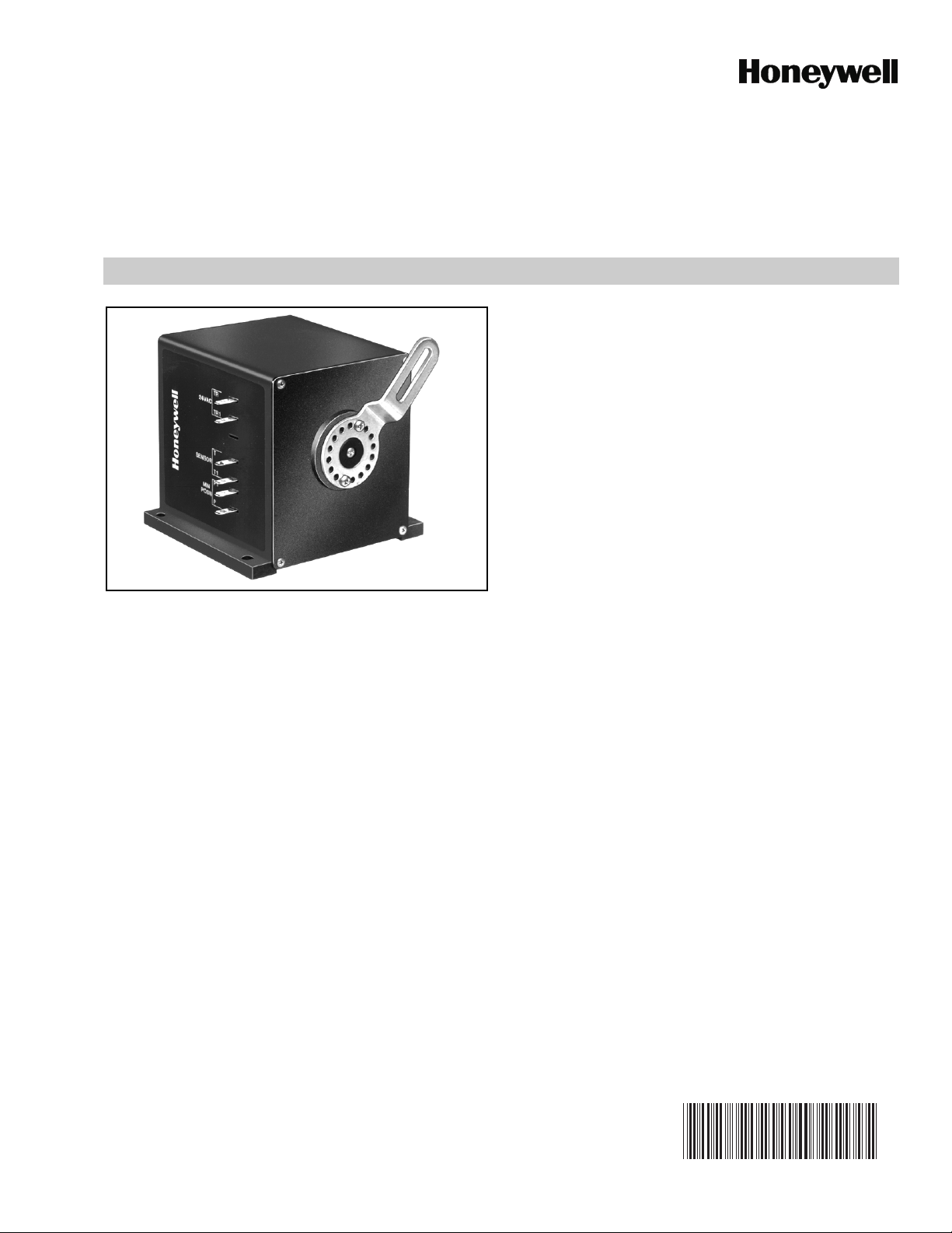
M7215
Damper Motors
PRODUCT DATA
FEATURES
• M7215 Damper Motors provide modulating control of
economizer dampers from a 2-10 Vdc controller.
• Quiet, high efficiency drive motor.
• High impact, glass-fiber reinforced plastic case is
rugged, lightweight and corrosion resistant.
• Provides 2-10 Vdc output signal proportional to the
shaft position.
APPLICATION
M7215 Damper Motors provide 25 lb-in. torque with spring
return and 2-10 Vdc modulating control of economizer
systems, ventilation dampers and combustion air dampers
used in residential or commercial HVAC equipment.
Contents
Application ........................................................................ 1
Features ........................................................................... 1
Specifications ................................................................... 2
Ordering Information ........................................................ 2
Installation ........................................................................ 3
Operation and Checkout .................................................. 4
Page 2

DAMPER MOTORS
7/16
(11)
1-1/4
(32)
5-3/16 (132)
4-1/2 (114)
3-1/2 (89)
2-1/4 (57)
4-1/2
(114)
5
(127)
4-1/32
(102)
1-3/8 (35)
3-1/8 (79)
M3851
TOP VIEW SIDE VIEW POWER END VIEW
1/4 (6)
4-1/2
(114)
SPECIFICATIONS
Models: ML7215: 25 lb-in. (2.8 N•m) torque, foot-mounted
spring-return damper motor with 2-10 Vdc feedback signal.
Accepts 2-10 Vdc control signal.
Dimensions: See Fig. 1.
Electrical Ratings:
Supply Voltage: 24 ±6 Vac 50/60 Hz.
Power Consumption:
24 Vac, 60 Hz: 8.7 VA.
24 Vac, 50 Hz: 8.4 VA.
Torque :
Lift and Hold: 25 lb-in. (2.8 N•m).
Spring Return: 25 lb-in. (2.8 N•m).
Breakaway: 40 lb-in (4.5 N•m).
IMPORTANT
Never use motor continuously at the breakaway
torque rating.
NOTE: NOTE:Breakaway torque available to overcome
occasional large loads such as a seized damper.
Stroke:
Travel: 90°.
Timing:
Driving: 86 ±5 seconds.
Spring Return: 13 ±5 seconds.
Motor Rotation (Viewed From Shaft End):
Closed Position: Limit of clockwise rotation.
Open Position: Limit of counterclockwise rotation.
Crank Arm Rotation Limits: See Fig. 2.
Shipped with shaft in closed position.
Ambient Ratings:
Temperature:
Operating: -25°F to +125°F (-32°C to +52°C).
Storage: -30°F to +150°F (-34°C to +66°C).
Humidity: 5 to 95 percent relative humidity, noncondensing.
Terminal Connections: 1/4 in. (6 mm) quick-connect
terminals mounted on motor.
Shaft: Single-ended drive shaft with crank arm supplied.
Reliability:
Full-Stroke Cycles: 60,000.
Repositions: 1,500,000.
Approvals:
Underwriters Laboratory Inc.:
Flammability Rating: UL94-5V.
Component Recognized: File No. E4436, Guide No.
XAPX2, Vol. 9, Section 1, 7-25-83.
Accessories: See Table 1.
Fig. 1. M7215 Damper Motor dimensions in in. (mm).
ORDERING INFORMATION
When purchasing replacement and modernization products from your TRADELINE® wholesaler or distributor, refer to the
TRADELINE® Catalog or price sheets for complete ordering number.
If you have additional questions, need further information, or would like to comment on our products or services, please write or
phone:
1. Your local Honeywell Automation and Control Products Sales Office (check white pages of your phone directory).
2. Honeywell Customer Care
1885 Douglas Drive North
Minneapolis, Minnesota 55422-4386
In Canada—Honeywell Limited/Honeywell Limitée,
International Sales and Service Offices in all principal cities of the world. Manufacturing in Australia, Canada, Finland, France,
Germany, Japan, Mexico, Netherlands, Spain, Taiwan, United Kingdom, U.S.A.
63-2556—01 2
Page 3

Table 1. M7215 Accessories.
CAUTION
CAUTION
M3852
1
1
CRANK ARM FIELD ADJUSTABLE IN 7.5 DEGREE INCREMENTS.
MOTOR MOUNTING SURFACE
M3850
MAXIMUM
OPEN
POSITION
MAXIMUM
CLOSED
POSITION
7640QF Terminal Enclosure—provides wiring enclosure for
electrical terminal connections. Enclosure can be used with or
without 40784EHB Screw Terminal Adapter. Bag assembly
includes: terminal housing, cover plate and mounting screws.
4074EGR Crank Arm Assembly.
Q298B Linkage Hardware—enables linking the motor to an
additional damper. Consists of two crank arm assemblies, two ball
joint assemblies, and variable length push rods (in 10, 16, or 24
inch lengths)
4074EKV Auxiliary Switch—provides switching capability for
controlling auxiliary equipment. The switch acts as a function of the
motor shaft position.
DAMPER MOTORS
M3855
M3856
M17364
Fig. 2. Limits of crank arm rotation.
INSTALLATION
When Installing this Product...
1. Read instructions carefully. Failure to follow them could
damage the product or cause a hazardous condition.
2. Check ratings and description given in the specifications
to make sure the product is suitable for your application.
3. Installer must be a trained, experienced service technician.
4. After installation is complete, check out product
operation as provided in these instructions.
Electrical Shock or Equipment Damage Hazard.
Can shock individuals or short equipment
circuitry.
Disconnect power supply before installation.
Personal Injury Hazard.
Spring-return assembly can release.
Leave end covers attached to the motor.
Location and Mounting
Locate motor as close as possible to the equipment to be
controlled. Refer to Fig. 1 for mounting dimensions.
1. Mount motor with the shaft horizontal to ensure
maximum life.
NOTE: NOTE:Operation in other positions is possible
when required by the application.
2. Remove crank arm (secured with two screws) from the
motor hub.
IMPORTANT
Position crank arm on hub so it does not strike motor
mounting surface during any portion of full stroke.
See Fig. 2.
3. Reposition the crank arm to accommodate specific
damper requirements.
NOTE: NOTE:Crank arm position is adjustable in eight
degree increments.
4. Reconnect crank arm to the motor hub.
3 63-2556—01
Page 4

DAMPER MOTORS
CAUTION
M17365
TR1
TR
M7215
2-10
VDC
CONTROL
METER INDICATING
MOTOR POSITION
(2-10 VDC)
L1
L2
IN+
OUT
–
IN–
+
–
OUT
+
DOTTED LINE REPRESENTS INTERNAL
CONNECTIONS OF THE M7215 ACTUATOR.
1
1
5. If there is an excess length of linkage rod, cut it to size.
Make necessary minor adjustments until desired
operation is obtained.
6. Tighten all nuts and set screws.
WIRING
Electrical Shock or Equipment Damage Hazard.
Can shock individuals or short equipment
circuitry.
Disconnect power supply before installation.
All wiring must comply with applicable codes and ordinances.
Refer to Fig. 3 and 4 for typical hookups.
Fig. 3. Typical M7215 wiring.
OPERATION AND CHECKOUT
The M7215 Damper Motor accepts input from a 2-10 Vdc
controller. The motor can be checked out either directly or by
using a controller.
4. If questions arise regarding this product, contact
your distributor or local Honeywell representative.
M7215
IN+
CONTROL
2-10
VDC
CONTROL
1
POWER SUPPLY. PROVIDE
DISCONNECT MEANS
AND OVERLOAD
PROTECTION AS REQUIRED.
2
DOTTED LINE REPRESENTS
INTERNAL CONNECTIONS
OF THE M7215 ACTUATOR.
3
MAKE SURE THAT ACTUATORS
ARE WIRED IN PHASE
TR TO TR AND TR1 TO TR1.
MOTOR
IN–
OUT
–
OUT
+
+
–
IN+
IN–
OUT
OUT
IN+
IN–
OUT
OUT
–
+
–
+
TR
2
TR1
M7215
CONTROL
MOTOR
TR
2
TR1
M7215
CONTROL
MOTOR
TR
2
TR1
1
(HOT)
3
M17366
L1
L2
Fig. 4. Three M7215 Damper Motors connected in parallel.
Direct Checkout
1. Mount the motor for the required application.
2. Check the damper position and make sure 24 Vac is
present across TR and TR1.
3. Apply 10 Vdc to IN+ and IN- to move damper to the
opposite position. The motor should drive the damper.
4. If the motor does not run, verify that the motor and crank
arm are properly installed for either clockwise or
counterclockwise rotation.
5. If installation is correct, but the motor does not run,
replace the motor.
IMPORTANT
1. If necessary, release one of the previously tightened
linkage connections to prevent damage.
2. Check for proper operation, making sure that the linkage does not bind and that the motor travels smoothly
throughout its cycle from fully open to fully closed.
NOTE: NOTES:This motor checkout assures that:
1. The motor operates the load.
2. The motor responds properly to the controller.
3. There is no linkage binding or motor stalling at
any point of travel.
Automation and Control Solutions
Honeywell International Inc. Honeywell Limited-Honeywell Limitée
® U.S. Registered Trademark
© 2009 Honeywell International Inc.
63-2556—01 E.K. Rev. 04-09
Controller Checkout
1. Adjust controller setpoint to call for cooling. Observe the
motor.
2. If the damper is closed, it should begin to open.
3. If the damper remains closed, move controller setpoint
farther below room temperature.
4. If the damper still does not move, check for the
presence of 24 Vac in the input.
5. If 24 Vac is present and motor does not operate, reverse
controller leadwires to determine if device was miswired.
6. If the wiring is correct and 24 Vac is present on the input
terminals but the motor does not run, replace the motor.
By using this Honeywell literature, you agree that Honeywell will have
no liability for any damages arising out of your use or modification to,
the literature. You will defend and indemnify Honeywell, its affiliates
and subsidiaries, from and against any liability, cost, or damages,
including attorneys’ fees, arising out of, or resulting from, any
modification to the literature by you.
 Loading...