

Page 1

Honeywell Connected Life Safety Services
GLSS Gateway
Installation and User’s Manual
LS10237-000NF-E | REV. A | 31/01/2020
Page 2

Table of Contents
Section 1: General Information.........................................................................................................................................4
1.1: About This Manual .......................................................................................................................................................................4
1.2: Information Sources....................................................................................................................................................................4
1.3: Documentation Feedback ........................................................................................................................................................5
1.4: Abbreviations Used in This Document ................................................................................................................................5
1.5: FCC STATEMENT...........................................................................................................................................................................6
1.6: Warnings and Cautions..............................................................................................................................................................6
1.7: Disclaimer.........................................................................................................................................................................................6
Section 2: Overview..............................................................................................................................................................7
2.1: Operations........................................................................................................................................................................................7
2.2: Honeywell Connected Life Safety Services.......................................................................................................................7
2.3: The Gateway Board’s Layout....................................................................................................................................................7
2.3.1: Connecting Interfaces ....................................................................................................................................................8
2.3.2: LED Indicators....................................................................................................................................................................9
2.3.3: Switches on the Gateway Board ..............................................................................................................................11
Section 3: Installation.......................................................................................................................................................12
1.1: Wall Mounting the Dedicated Gateway............................................................................................................................12
3.2: Gateway Board Connections.................................................................................................................................................14
3.2.1: Connecting to a Fire Alarm Panel...........................................................................................................................15
Supported Panels.................................................................................................................................................................15
Vigilon Panels: Connection Options............................................................................................................................15
Notifier Panels: Connection Options...........................................................................................................................15
To Make a USB Connection.............................................................................................................................................16
To Make a NUP/RS232 Connection ..........................................................................................................................16
The panel supplies the 24V DC power to the gateway board through the NUP connection. ...........16
To Make a UART/TTL Connection................................................................................................................................16
Section 4: Configurations................................................................................................................................................18
4.1: Panel Configurations ...............................................................................................................................................................18
4.1.1: The Date Settings...........................................................................................................................................................18
4.2: Gateway Configurations .........................................................................................................................................................18
4.2.1: To Configure via the Wireless Connection..........................................................................................................18
4.3: Verifying the Gateway Connections...................................................................................................................................20
4.4: Testing the Commissioning...................................................................................................................................................20
2
Page 3

Table of Contents
Section 5: Post-Installation Activities .........................................................................................................................22
5.1: Maintenance Testing................................................................................................................................................................22
5.2: Upgrading the Gateway Firmware......................................................................................................................................22
5.2.1: To Upgrade to a Later Release.................................................................................................................................22
5.2.2: To Verify the Upgrade...................................................................................................................................................23
5.2.3: LED Indications During the Upgrade....................................................................................................................23
5.3: Troubleshooting..........................................................................................................................................................................24
5.3.1: To Troubleshoot LED-Indicated Issues................................................................................................................24
5.3.2: To Troubleshoot Other Issues...................................................................................................................................25
Appendix A: Gateway Operating Conditions..............................................................................................................26
Appendix B: Modulations and Power Used.................................................................................................................27
3
Page 4

Section 1: General Information
1.1 About This Manual
This GLSS Gateway Installation and User’s Manual provides detailed procedures about
installation, deployment, and upgrade of Honeywell Connected Life Safety Services. The
manual describes:
• the dedicated CCM gateway,
• its installation environment,
• mounting and connecting the gateway circuit board to a fire detection panel, and
• initial network configurations
Using This Manual This manual is written with the understanding that the user is
trained in the operations and services required for this product.
NOTE:In this manual, the GLSS Gateway’s printed circuit board is also called as the
gateway board.
1.2 Information Sources
The table below lists related documents:
Table 1.1: Supplemental Documents
Product Type: Honeywell Connected Life Safety Services Gateway
For This Purpose ... Refer to ...
Get comprehensive
installation and
configuration process
details
Product Type: Notifier Panels
For This Purpose ... Refer to ...
NCA Panel
Install the NCA panel NCA Installation Manual
NCA-2 Panel
Install the NCA-2
panel
NFS-320 Panel
Install the NFS-320
panel
Customize the NFS320 panel
Operate the NFS-320
panel
NFS2-640 Panel
Install the NFS2-640
panel
Customize the NFS2640 panel
Operate the NFS2-640
panel
NFS-3030 Panel
Install the NFS-3030
panel
Customize the NFS3030 panel
GLSS Gateway Installation and User’s Manual (This document)
Part Number 50151849-001
51482
NCA-2 Installation Manual
52482
NFS-320 Installation Manual
52745
NFS-320 Programming Manual
52746
NFS-320 Operations Manual
52747
NFS2-640 Installation Manual
52741
NFS2-640 Programming Manual
52742
NFS2-640 Operations Manual
52743
NFS-3030 Installation Manual
51330
NFS-3030 Programming Manual
51344
4
P/N: LS10237-000NF-E | Rev A.
Page 5

Documentation Feedback
Product Type: Honeywell Connected Life Safety Services Gateway
Operate the NFS-3030
panel
NFS2-3030 Panel
Install the NFS2-3030
panel
Customize the NFS23030 panel
NFS-3030 Operational Manual
51345
NFS2-3030 Installation Manual
52544
NFS2-3030 Programming Manual
52545
Operate the NFS23030 panel
NFS2-3030 Operations Manual
52546
1.3 Documentation Feedback
Your feedback helps us keep our documentation up-to-date and accurate. If you have any
comments or suggestions about our Online Help or printed documents, you can email us.
Please include the following information:
• Product name and version number (if applicable)
• Printed document or Online Help
• Topic title (for Online Help)
• Page number (for printed document)
• A brief description of content you think should be improved or corrected
• Your suggestion for how to correct/improve documentation
Send email messages to:
FireSystem.TechPubs@Honeywell.com
Please note this email address is for documentation feedback only. If you have any
technical issues, please contact Honeywell Technical Services.
1.4 Abbreviations Used in This Document
Table 1.2: Abbreviations List
Abbreviation Description
DACT Digital Alarm Communicator Transmitter
ESD Engineered Systems Distributor
NFN Noti-FIRE-Net Network
NUP Notifier Universal Protocol
The Universal Protocol by Notifier for all fire alarm panel communications. This
protocol enables direct transfer of data between the panels and networks,
without the need to translate.
OC Ownership Code
The code that confirms ownership of the gateway
TTL Transistor-Transistor Logic
A physical connection for performing both the logic gating and amplifying
functions on the serial data.
UART Universal Asynchronous Receiver/Transmitter
A physical connection that converts and provides serial data for the panel and
parallel data for the gateway.
USB Universal Serial Bus
5
P/N: LS10237-000NF-E | Rev A.
Page 6
FCC STATEMENT
!
1.5 FCC STATEMENT
This device complies with Part 15 of the FCC Rules. Operation is subject to the following
two conditions: (1) This device may not cause harmful interference. (2) This device must
accept any interference received, including, an interference that may cause undesired
operation.
FCC ID: PV3CGWMB
1.6 Warnings and Cautions
CAUTION:USERS MUST FOLLOW THE PROCESSES AND USAGES APPROVED AS PER
COMPLIANCE. A CHANGED OR MODIFIED USAGE NOT EXPRESSLY APPROVED BY
COMPLIANCE COULD VOID THE USER'S AUTHORITY TO OPERATE THE GLSS
GATEWAY.
WARNING:
THESE INSTRUCTIONS CONTAIN PROCEDURES TO FOLLOW TO AVOID INJURY AND
DAMAGE TO EQUIPMENT. IT IS ASSUMED THAT THE USER OF THIS MANUAL HAS BEEN
SUITABLY TRAINED AND IS FAMILIAR WITH THE RELEVANT REGULATIONS.
ELECTRO-STATIC SENSITIVE DEVICES:
TAKE SUITABLE ESD PRECAUTIONS WHEN REMOVING OR INSTALLING PRINTED
CIRCUIT BOARDS.
THIS GATEWAY’S PANEL IS CE MARKED TO SHOW THAT IT CONFORMS TO THE
REQUIREMENTS OF THE FOLLOWING EUROPEAN COMMUNITY DIRECTIVES:
• EMC Directive 2014/30/EU
• Low Voltage Directive (LVD) 2014/35/EU
• Radio Equipment Directive 2014/53/EU
• RoHS Directive 2011/65/EU
• WEEE Directive 2012/19/EU
The gateway is designed to meet Additional National Requirements: EFSG [BRE,
AFNOR/CNPP, and VdS], Incert, SBSC, EMEA, and EAC
1.7 Disclaimer
Images in the document are for reference purpose only and are subject to change. All
trademarks, service marks, word marks, design marks, and logos are property of their
respective owners.
6
Page 7
Section 2: Overview
!
Tamper Switch 2
(On the back side)
GLSS Gateway is an embedded and intelligent gateway for connected buildings. It enables system
maintenance providers as well as end users to remotely manage connected fire detection systems. The
gateway also supports them to ensure compliance.
CAUTION: THE GATEWAY MUST BE INSTALLED INDOORS.
2.1 Operations
The gateway acts as a portal among fire alarm panels, Cloud, and peripheral devices. The gateway
connection with the fire alarm panel enables reading the inventory and transmitting the data. The
connection with Cloud facilitates remotely monitoring and managing the fire detection systems.
2.2 Honeywell Connected Life Safety Services
The software suite enables remote management of fire detection systems. It monitors the building’s fire
system events in real-time and notifies users about the events immediately. It also supports periodical
maintenance activities and helps in reports generation.
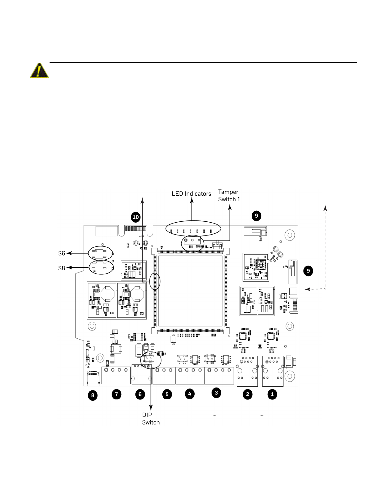
2.3 The Gateway Board’s Layout
The illustration below points out those parts that are used for connections and trouble shooting.
Figure 2.1: Printed Circuit Board: Layout
7
Page 8

The Gateway Board’s Layout
2.3.1 Connecting Interfaces
Figure 2.1
these numbered labels at various places for your convenience.
The table below uses these numbered labels to describe the type and usage of the interfaces.
uses numbered labels to show the location of the interfaces for connections. This manual uses
Table 2.1: Gateway Interface Details
Label
No.
Interface Type Usage
1 Ethernet 1 Primary Ethernet port that can permanently connect the gateway board with
the CLSS Cloud services.
Cable: CAT 5 standard Ethernet cable with RJ45 connector
2 Ethernet 2 Secondary Ethernet port providing a TCP/IP connection to one of the
compatible Notifier panel.
Cable: CAT 5 standard Ethernet cable with RJ45 connector
3 RS485B For future use
4 RS485A For future use
5 UART/TTL Connects the gateway board to a UART/TTL-compatible fire alarm panel.
This connection enables the fire alarm panel to send the alarm data and
device data to the gateway.
6 NUP (RS232) Transfer of fire-related and device-related data from the panel to Cloud
through the gateway. It also helps in administering the fire detection system.
Connects the gateway board to one of the following:
• An NFN network control module (NCM, NCM-2, or HS-NCM)
• A Notifier panel
If the connected panel supplies power, the gateway would get power from the
panel through the NUP port.
7 Power Connects to an external 24-volt DC power when required. It uses a power-
limited, regulated, power-supply-listed connection for fire-protective
signaling.
It is used only when the gateway board is connected with:
• A network card, or
• A Notifier panel through USB
8 USB Transfer of fire-related and device-related data from the panel to Cloud
through the gateway. It also helps in administering the fire detection system.
Connects to a Notifier panel
9 Wireless
Antennas
Enables the gateway to have a wireless or mobile Low Energy Antennas for
communication with Cloud
10 Cellular Enables the gateway to report alarms and supervision messages to a central
receiving station. It is a 40-pin expansion slot for an LTE communicator.
8
Page 9
The Gateway Board’s Layout
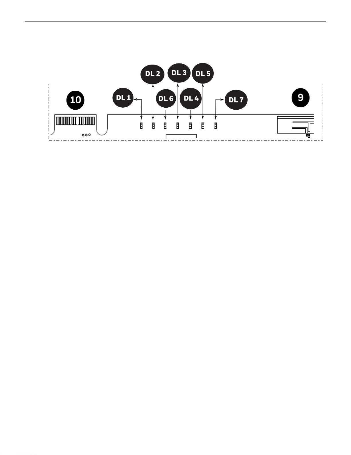
2.3.2 LED Indicators
The LED indicators on the GLSS Gateway board use different colors to identify various operational status of
the gateway. To know the location of the LED indicators on the gateway board, refer
Circuit Board: Layout” on page 7
Figure 2.1: “Printed
.
Figure 2.2: The LED Indicators on the Gateway
9
Page 10

The Gateway Board’s Layout
Table 2.2: LED Indicators and Their Messages
SOM
Power-Indicating LED
Indicates that the gateway board is using the received power.
ON The circuit board is receiving its 24V power from its power source.
OFF The circuit board is not receiving the power.
DL1
LTE Power LED
Indicates power supply for the cellular communications.
For future use.
DL2
Trouble LED
Indicates the gateway’s operational status.
OFF There are no issues.
FLASHING SLOW (flashes per 1 second). There are communication issues with the panel
or the Internet connectivity.
ON There is a critical error in the system.
To fix the issues, you can refer to the
5.3, "Troubleshooting"
section, which discusses
about a few issues and their solutions.
DL6
Mobile Connectivity
Indicates the status of mobile communications between the Cloud and the mobile app.
FLASHING SLOW (flashes per 1 second) indicates that the mobile connectivity is
available, but not yet connected to the app.
FLASHING FAST (flashes per 0.25 second) indicates that the gateway is connected to the
CLSS app.
OFF The mobile connectivity is disabled.
DL3
Panel Connectivity
Indicates the connectivity status of the panel.
FLASHING SLOW (flashes per 1 second). A flashing Green indicates that the panel is
connected with the gateway board.
FLASHING FAST A flashing Green per 0.2 second indicates that the gateway is fetching
the inventory data from Cloud.
ON Configuration mode is enabled for configuring the gateway network settings.
OFF The gateway is not communicating with the panel.
DL4
Cloud Connectivity
Indicates the gateway connection status with Cloud.
ON The gateway is downloading the firmware from Cloud.
FLASHING SLOW A flashing Green once per second indicates that the gateway is
connected with Cloud.
FLASHING FAST A flashing Green per 0.2 second indicates that the gateway is connected
with Internet, but not connected with Cloud.
OFF The gateway does not have Internet connectivity.
DL5
Wireless Connectivity
Indicates the gateway connectivity status with wireless devices.
FLASHING SLOW (flashes per 1 second). The wireless connectivity is enabled for the
Cloud connection.
OFF The wireless connectivity is disabled.
10
Page 11

The Gateway Board’s Layout
DL7
Cellular Connectivity
Indicates the gateway connectivity status with cellular devices.
FLASHING SLOW (flashes per 1 second). The cellular connectivity is enabled for the
Cloud connection.
OFF The cellular connectivity is disabled.
2.3.3 Switches on the Gateway Board
Below table describes about the switches on the gateway board. To locate the switches on the gateway
board, refer
Figure 2.1: “Printed Circuit Board: Layout” on page 7
Table 2.3: Gateway Board Switches
Switches Purpose
S6 For securely configuring the gateway’s network settings. Pressing the switch for
six seconds switches the gateway board to the configuration mode.
S7 For changing the direction of the 24V power of the NUP connector.
NUP IN: The gateway board receives power from the NUP connection.
NUP OUT: The gateway board supplies power to the NUP connection.
S8 For enabling mobile pairing. Pressing the switch for ten seconds enables mobile
pairing.
S6 and S8 For reverting to factory default settings. Pressing both of them together for ten
seconds will start the factory resetting process. The factory resetting process
takes 10 minutes to complete.
Tamper 1 For alerting whenever the door is opened. It is located at the front-side of the
gateway, next to the LED indicators.
Tamper 2 For alerting whenever the gateway board is removed from the enclosure. It is
located at the backside of the gateway.
.
11
Page 12

Section 3: Installation
!
!
Enclosure door
Knock out
for screw hole
You can use a fixed gateway or a portable gateway in the fire detection system.
Fixed gateway: Permanently connects the gateway with the building’s fire detection system
Portable gateway: Helps to configure the fire detection system and synchronizes data
CAUTION: THE GATEWAY MUST BE INSTALLED INDOORS.
1.1 Wall Mounting the Dedicated Gateway
Distance between the gateway and the panel depends upon the length of connecting cables. The
maximum distance between them should be 0.9144 meter (36 inches).
CAUTION: THE EQUIPMENT IS SUITABLE FOR MOUNTING AT A MAXIMUM HEIGHT OF 9.9
FEET ONLY.
Follow the instructions below to mount the gateway enclosure:
1. Open the package and take out the contents.
2. Inspect the contents for damage. If there is any damage, do not proceed with installation. Return the
package.
3. Using an Allen key, open the enclosure door.
4. Place the right-side door edge on a flat surface for support.
5. At the right-side door edge, punch out a hole for the screw lock.
Figure 3.1: Screw Hole Knock Out
6. Depending upon the wall construction, select suitable screws to mount the enclosure.
7. Place the backbox on the wall where the enclosure is to be mounted.
8. Confirm that the placement of the backbox allows the door to swing open freely.
12
Page 13

Wall Mounting the Dedicated Gateway
9. Mark and pre-drill the hole for the top keyhole mounting bolt.
Figure 3.2: Backside of the Gateway Enclosure
10. Remove the backbox.
11. In the top mounting hole, insert the mounting screw.
12. Tighten the screw, leaving required space for hanging the enclosure.
13. Mount the backbox over the top screw and level it.
14. Mark the locations for the two lower mounting holes.
15. Remove the backbox and drill the mounting holes.
16. Mount the backbox over the top screw, then install the remaining fasteners.
17. Tighten all fasteners securely.
13
Page 14

Gateway Board Connections
A
B
Fire Alarm Panel
CLSS
Cloud
Configuration
Computer
Mobile
Connection
Wireless
Connection
Ethernet Connection
3.2 Gateway Board Connections
The gateway board can be connected with a CLSS Cloud, a configuration computer, a panel, a mobile
device, and an external power supply.
Figure 3.3: Gateway Connections
14
Page 15

Gateway Board Connections
3.2.1 Connecting to a Fire Alarm Panel
The panel to which the gateway board connects acts as the master panel. It collects data from all its
devices, and sends the collected data to the gateway.
WARNING: CONNECTIONS BETWEEN THE GATEWAY, CLOUD, AND THE MASTER PANEL MUST BE
PERMANENT.
NOTE: The interfaces of the gateway board and panel must be connected with compatible cables only.
Supported Panels
To know about supported panel variants and their connection options, refer below:
•
“Vigilon Panels: Connection Options” on page 15
•
“Connection Options” on page 15
Vigilon Panels: Connection Options
Each variant of the Vigilon panel offers various connection options.
The gateway operates only with these Vigilon fire alarm control panels listed in the below table:
Table 3.1: Connection Options
Fire Alarm Panel Models USB RS232 UART/TTL
COMPACT-24-N Yes Yes No
COMPACT-PLUS Yes Yes No
VIGPLUS-24 Yes Yes Yes
VIGPLUS-72 Yes Yes Yes*
VIG1-24 Yes Yes Yes*
VIG1-72 Yes Yes Yes*
* Use the add-on I/O card (VIG-IOC-DOM).
*
Notifier Panels: Connection Options
Each variant of the Notifier panel offers various connection options.
The gateway operates only with these Notifier fire alarm control panels listed in the below table:
Table 3.2: Connection Options
Fire Alarm Panel Models USB
NCA No Yes
NCA-2 No Yes
NFS-320 No Yes
NFS-640 No Yes
NFS2-640 No Yes
NFS-3030 No Yes
NFS2-3030 No Yes
NCM-W No Yes
NCM-F No Yes
HSNCM-W No Yes
HSNCM-MF No Yes
HSNCM-SF No Yes
HSNCM-WMF No Yes
HSNCM-WSM No Yes
HSNCM-MFSF No Yes
NUP
(RS232)
15
Page 16

Gateway Board Connections
To Make a USB Connection
On the Gateway Side
1. Connect the USB-C side of the cable to the USB port of the gateway.
The USB port is labeled as 8 in the figure
On the Panel Side
1. Connect the USB-A side of the cable to the USB port of the panel.
To know more about the panel-side connection steps, refer to the installation document of the respective
panel.
Power Connection
After connecting the gateway to the panel through USB, connect the gateway with an external power
source for its 24V DC power.
NOTE: This external power connection should be power limited, UL864-listed, and approved for fire alarm
signaling.
To Make a NUP/RS232 Connection
On the Gateway Side
1. Connect the NUP cable to the NUP port of the gateway board.
The NUP port is labeled as 6 in the figure
2. Find the SW7 switch next to the NUP port, and switch it to towards NUP_IN.
“Gateway Connections” on page 14
“Gateway Connections” on page 14
.
.
Figure 3.4: DIP Switch
On the Panel Side
Connect the NUP cable to the NUP port of the panel.
Power Connection
The panel supplies the 24V DC power to the gateway board through the NUP connection.
To Make a UART/TTL Connection
A UART/TTL interface can connect the gateway board with the UART/TTL port of the panel.
On the Gateway Side
1. Connect the male UART/TTL cable to the Rx (Red), 0V (Silver), and Tx (White) terminals of the gateway.
The UART/TTL port is labeled as 5 in the
“Gateway Connections” on page 14
On the Panel Side
1. Within the panel, find the backplane PCB board.
2. Connect the 1.5mm phono socket to the P11 connector on the panel’s PCB.
.
16
Page 17

Gateway Board Connections
Figure 3.5: UART/TTL Connections
17
Page 18

Section 4: Configurations
The gateway settings control the gateway’s communications with the mobile, panel, devices, and Cloud.
4.1 Panel Configurations
4.1.1 The Date Settings
To enable gateway communications with Cloud, the date and time must be set correctly in the connected
panel.
4.2 Gateway Configurations
The first-time commissioning of the gateway fetches the data from the panel and sends to Cloud.
Subsequent connections synchronize the data between the panel and the Cloud.
4.2.1 To Configure via the Wireless Connection
1. In the mobile device, from Play Store or App Store, download the Connected Life Safety Services app.
2. Install the app.
3. From the Honeywell on-boarding email, take the login credentials.
4. On the mobile, log into the CLSS app.
5. On the app’s dashboard, at the right bottom, tap the More icon.
6. Tap Gateway Configuration.
7. Follow the on-screen instructions for mobile connectivity.
NOTE: Based on the gateway you are configuring, select either Portable Gateway or Fixed Gateway.
8. Wait for the app to connect with the gateway, the fire alarm panel, Internet, and Cloud.
The app notifies about the configuration completion.
9. On the dashboard, from the All Customers option, find the required customer > site.
18
Page 19

Gateway Configurations
10. Tap on the specific building.
11. To commission the gateway, tap on CONNECT GATEWAY and follow the on-screen instructions.
19
Page 20

Verifying the Gateway Connections
DL2
DL6
(
Blue Colour
)
(Amber Colour)
Mobile Connection
DL3
Configuration mode
DL4
Cloud connection
DL5
Wireless connection
Troubles
Power LED
S8
4.3 Verifying the Gateway Connections
While configuring the gateway, confirm the following LED indicators for successful connections:
Figure 4.1: Connection Indicators
LED Indicator State Meaning
Power-Indicating LED
DL2 OFF There are no issues
DL6
DL3 ON The gateway is in the configuration mode
DL4 Flashing slow The gateway is communicating with Cloud
DL5 Flashing slow The gateway has wireless connection with
* FLASHING FAST = 0.2 second ON and 0.2 second OFF
† FLASHING SLOW = 1 second ON and 1 second OFF
If the LED is indicating differently, refer to the
page 10
to know the operational status. If there is an issue, refer to the
fix it or contact Honeywell technical support.
4.4 Testing the Commissioning
After all the CLSS app configurations are done, if required, you can perform a commissioning test.
NOTE: The commissioning test does not generate reports.
1. On the app’s dashboard, at the bottom, tap the CheckPoint icon.
2. On the All Customers screen, find the customer > site, and then tap on the specific building.
3. On the building's dashboard, tap Start New Test.
4. On the Select Test Type, tap Commissioning.
ON
Flashing fast
Flashing slow
*
†
Successful power connection
Successful mobile connection
Ready for connection
OFF Disabled mobile connection
Flashing fast The gateway is fetching the inventory data
Flashing slow The gateway is communicating with the
panel
Flashing fast The gateway has Internet connectivity, but
not the Cloud connectivity
Cloud
Table 2.2, “LED Indicators and Their Messages,” on
5.3, "Troubleshooting"
section to
20
Page 21

Testing the Commissioning
5. Follow the on-screen instructions.
21
Page 22

The system maintenance provider is responsible for the maintenance and upkeep of GLSS Gateway. The
maintenance involves avoiding potential issues, taking regular backups, restoring data when required,
collecting data for troubleshooting, and so on.
5.1 Maintenance Testing
You can create and offer test plans for a building’s maintenance tests. A test plan shows the devices to be
tested and the type of tests for each device.
NOTE: In the app, the option to enable the control functionality is available for a duration. The duration is:
60 minutes to 10 hours.
1. On the All Customers screen, find the customer > site, and then tap on the specific building.
2. At the bottom, tap the CheckPoint icon, and then tap on the building.
3. Connect to the gateway.
4. Tap START NEW TEST.
5. From the Select Test Type menu, select Maintenance.
6. In the Test Name field, provide a name for the test.
7. From the Select Devices for Testing section, select the required test type:
• All Devices: Select it to test all devices or to create a test plan.
• Test Plans: Reuse already created test plans.
• Past Test Session: Choose a test session, which was performed earlier.
8. To create a new test plan, tap All Devices.
9. From the inventory list, include or exclude devices to be tested..
10. Tap SAVE & NEXT.
From the ACTIVE TESTS list, your test plan opens.
11. On the test plan, tap Enable Control.
12. From the devices list, find the device to be tested, and tap on the More icon.
13. Select the type of tests to be done for the device.
14. Repeat steps 11 and 12 until all the required devices and test types are configured.
15. Start the test.
Section 5: Post-Installation Activities
5.2 Upgrading the Gateway Firmware
Honeywell periodically releases updates and upgrades to the gateway’s firmware. Using the Gateway
Configuration tool you can securely make the firmware upgrade to the gateway.
5.2.1 To Upgrade to a Later Release
1. On the gateway side: Connect an Ethernet cable to the Ethernet port.
The port is labeled as 2 in the
2. On the configuration computer side: Connect the Ethernet cable to the configuration
computer’s Ethernet port.
3. On the gateway board, find the S6 button.
4. To switch to the configuration mode, press the S6 button for a minimum of 6 seconds,
and then release it.
The LED indicator DL3 turns ON and SOLID, indicating that the configuration is enabled.
5. Open the Chrome browser and enter the following IP address for the configuration
tool: https://192.168.10.190:9443/config/index.html
6. In the Sign In page, enter the password.
7. In the list of settings options, click Diagnostic.
8. In the GATEWAY FIRMWARE UPGRADE section, click Choose File.
9. Select the firmware image file and click Choose.
10.Once the chosen file is uploaded, click Upgrade.
Figure 3.3: “Gateway Connections” on page 14
.
22
Page 23

Upgrading the Gateway Firmware
5.2.2 To Verify the Upgrade
1. After the restart, log into the configuration tool.
2. Click Diagnostic.
3. Click About and verify that the new version of the GLSS Gateway is shown.
5.2.3 LED Indications During the Upgrade
While the gateway is downloading the firmware, the Green-color LED indicator DL4 will be ON.
If the LED is indicating differently, refer
know the operational status. If there is an issue, refer to the
contact Honeywell technical support.
Table 2.2, “LED Indicators and Their Messages,” on page 10
5.3, "Troubleshooting"
to
section to fix it or
23
Page 24

Troubleshooting
5.3 Troubleshooting
Issues that may occur during the gateway’s operation can be resolved on your own or by contacting
Honeywell technical support. The issues can be either LED-indicated issues or other issues.
5.3.1 To Troubleshoot LED-Indicated Issues
When an LED status indicates issues, refer to the below table to know their possible fixes.
Table 5.1: LED-Indicated Issues and Possible Fixes
SOM: Power LED-Indicated Issues
Power LED Status Other LEDs’ Status Possible Fixes
OFF
ON
• All other LEDs are OFF • Ensure that the gateway board’s power
• All other LEDs are OFF • Do the following:
source is supplying the required 24V
electricity.
1. Remove all the connected cables.
2. Wait for one minute.
3. Reconnect all the cables.
4. Ensure that the gateway board is getting
its 24V electric power.
• If the above steps do not fix the issue,
contact Honeywell technical support.
DL2: Trouble LED-Indicated Issues
Trouble LED Status Other LEDs’ Status Possible Fixes
ON and SOLID Amber Any
Flashing Amber once per
second
Flashing Amber once per
second
• DL3 The panel LED is OFF
• DL4 The Cloud LED is flashing once per
second
• DL3 The panel LED is flashing once per
second
• DL4 The Cloud LED is OFF
• It is a critical issue. Contact Honeywell
technical support.
Check the following and correct if
necessary:
• The cable connections at the gateway’s
port and at the panel’s port
• The cable connecting the gateway board
and the panel
Check the following and correct if
necessary:
• Internet connectivity
• Eth1 cable connections at the gateway
board side and at the panel side
• The Eth1 cable
24
Page 25

Troubleshooting
OFF
Flashing Green every
0.25 second
OFF
DL3: Panel LED-Indicated Issues
Panel LED Status Other LEDs’ Status Possible Fixes
• DL2 The Trouble LED is OFF
Check the following and correct if
necessary:
• The cable connections at the gateway
board side and at the panel side
• The Eth2 cable connecting the gateway
board and the panel
DL4: Cloud LED-Indicated Issues
Cloud LED Status Other LEDs’ Status Possible Fixes
• DL3 The panel LED is flashing once per
second
• DL2 The Trouble LED is OFF
• Associate the gateway board with the user
account.
• Ensure that the user account is active.
• Ensure that the panel’s date and time are
correct.
DL5: Wireless LED-Indicated Issues
Wireless LED Status Other LEDs’ Status Possible Fixes
• DL3 The panel LED is flashing once per
second
• DL4 The Cloud LED is OFF
• Ensure that the WLAN settings in the
Gateway Configuration Tool are correct.
• Ensure that the building’s IP network has
Internet and Cloud connectivity.
DL6: Mobile LED-Indicated Issues
Mobile LED Status Other LEDs’ Status Possible Fixes
OFF
• DL3 The panel LED is flashing once per
second
• DL4 The Cloud LED is OFF
5.3.2 To Troubleshoot Other Issues
If there are issues, which are not shown by the LEDs, refer to the below table to know their possible fixes.
Table 5.2: Other Issues and Possible Fixes
Events-Related Issues
Issue Description Possible Causes Possible Fixes
Panel events are not
displayed on the Connected
Life Safety Services
• The gateway is dissociated • Associate the gateway board with the user
• The user account is not associated with
the gateway
• The panel’s date and time are incorrect • Ensure that the panel’s date and time are
1. On the gateway board, find the S8
button.
To find the S8 button, refer to
“Printed Circuit Board: Layout” on
page 7
2. Press the S8 button until the LED
account.
• Ensure that the user account is active.
correct.
.
indicator DL6 flashes fast,
indicating enabled mobile
connectivity.
Figure 2.1:
25
Page 26

Appendix A: Gateway Operating Conditions
Table B.1: Operational Requirements
Power Requirements
Nominal voltage range Consumes 12V to 40V DC from the panel or from an
external power source.
Current The power requirement varies with the number of
interfaces used.
Typical current consumption: 0.1A at 24V
Peak load: 0.25A at 24V
Room Conditions
Temperature -10°C to 60°C (14°F to 140°F)
Relative humidity 1% to 94% Non-condensing
26
Page 27

Appendix B: Modulations and Power Used
Radio devices operating on the below frequencies should not be installed next to each other.
Wireless Transmitter Specifications
VBAT = 3.6V
Ambient temperature = 25
Output power @module RF antenna port
Target Power that Meets Spectrum Mask and EVM Compliance
IEEE
802.11
11b CCK,
11g OFDM 6 to 54
11n OFDM MCS 0-7 20
Std Mod Rate BW Channel Power Units Tol. (dB)
11a OFDM 6-54
11n OFDM MCS 0-7 20
Mod Rate BW Channel Power Units Tol. (dB)
DSSS
° C
Table C.1: Wireless Power Specifications
2.4 GH z TX Power Specifications
1 to 11
Mbps
Mbps
Mbps
20
MHz
20
MHz
MHz
5 GH z TX Power Specifications
20
MHz
MHz
1-11 16 dBM +/-2.0
1-11 17 dBM +/-2.0
1-11 18 dBM +/-2.0
36-48
52-64
100-144
149-165
36-48
52-64
100-144
149-165
15 dBM +/-2.0
16 dBM +/-2.0
27
Page 28

12 Clintonville Rd
Northford, CT 06472
140 Waterside Rd
Leicester LE5 1TN, UK
(203) 484-7161
+44 (0) 203 4091779
©2020 Honeywell International Inc.
 Loading...