

Page 1

CF3680 2D Imager Module
For Customer-Facing Designs
Quick Start Guide
Aller à www.honeywellaidc.com pour le français.
Vai a www.honeywellaidc.com per l'italiano.
Gehe zu www.honeywellaidc.com für Deutsch.
Ir a www.honeywellaidc.com para español.
日本語 : www.honeywellaidc.com をご覧ください。
如要到中国 www.honeywellaidc.com(简体)。
查看繁体版请登陆 www.honeywellaidc.com
한글 www.honeywellaidc.com 로 이동합니다 .
CF3680-EN-QS-01 Rev B
2/17
Page 2

What is the CF3680 2D Imager Module?
The CF3680 is a 2D imager module designed to be integrated
into fixed mount enclosures, such as a self-service kiosk. It
includes:
• N3680 scan engine
• USB interface (USB-B connector)
•Exit window
• Movement detector used to start a reading session
• User feedback pins
Required Accessories
• Standard USB-A to USB-B cable
Additional Documentation
The following documents are available for the CF3680:
• CF3680 Installation Guide
• N3680/CF3680 User Guide
These documents are available from your local Honeywell OEM
representative.
Page 3
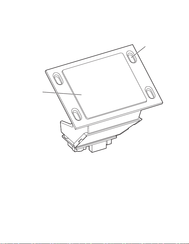
CF3680 Front View
Mounting
holes (x4)
Exit
window
Page 4
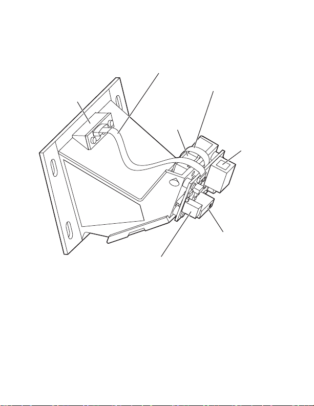
CF3680 Back View
Movement
detector
Ribbon cable
sensor to PCB
USB-B
connector
Distance selection
switch
User
feedback
pins
Scan
engine
Ribbon cable
engine to PCB
Page 5
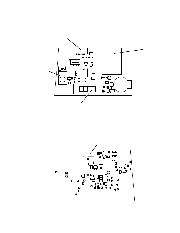
PCB View
1
2
1
6
1
5
1
Flex connector
to scan engine
Flex connector
to movement detector
USB-B
connector
User feedback
pins
Distance selection
switch
Page 6

Connecting the CF3680 to a Host
By default, the CF3680 is in USB PC Keyboard interface.
1. Connect a standard USB cable (standard USB-A to USB-B) to the CF3680 and to the USB port on the host.
2. Power-up the host.
3. Verify that the CF3680 is on by presenting a bar code in front of the scan window. The white LED should turn on and read the bar code.
Note: The CF3680 does not beep to indicate a good read unless
this has been setup by the user with the user feedback pins.
See the CF3680 Installation Guide for more details
(available from your local Honeywell OEM representative).
Page 7

Distance Selection Switch
2
1
6
1
5
1
Position
Use this switch to select the range to be used to detect an object
and trigger the scan engine. The distance is measured from the
outside of the exit window.
• Position 1—0 to 10 cm (4 in)
• Position 2—0 to 20 cm (8 in)
• Position 3—0 to 30 cm (12 in)
Note: Only position 1 is indicated on the PCB.
Page 8

Configuration
You can configure your scanner two ways:
• Reading configuration bar codes
• Using the EZConfig Cloud for Scanning tool
Configuration Bar Codes
Scan configuration bar codes to set up your scanner. All available configuration bar codes are available in the N3680 User’s
Guide. Contact your local Honeywell OEM representative for
more information.
EZConfig Cloud for Scanning Tool
Use the EZConfig Cloud for Scanning tool to configure your
scanner online:
1. Go to the Honeywell web site at
2. Click on the Browse Products tab. Under Software, select Device Management.
3. Click on EZConfig Cloud for Scanning.
4. Scroll to the bottom of the page and click on Register for free access now to sign up.
www.honeywellaidc.com
Page 9

Basic Setup
Here are some basic menu bar codes that may be useful for testing. For more setup options see the N36810/CF3680 User
Guide (available from your local Honeywell OEM representative).
Note: The * symbol indicates the default value.
Interface
For USB serial interface, you must install the USB driver before
connecting your scanner. Contact your local Honeywell OEM
representative to get the latest USB driver.
USB Serial Interface
USB PC Keyboard *
Page 10

Keyboard Country Layout
The default keyboard is United States.
French
Italian
German
All Symbologies
All Symbologies Off
All Symbologies On
Page 11

LED Illumination - Manual Trigger
Use this setting to change the LED illumination brightness.
Low *
Reset Factory Defaults
The following bar code resets factory defaults.
High
Page 12

Mechanical Dimensions
Page 13

A
A
Page 14

Mounting hole recess
(section A-A)
Page 15

User Feedback Pins
User feedback pins give you access to the trigger, beeper and
good read lines on the scan engine. See the CF3680 Installation
Guide for details on these pins (available from your local Honeywell OEM representative).
Exit Window
The exit window is made of chemically strengthened glass and
is scratch resistant. To clean the window, use one of the following:
®
•Sani-Cloth
•Sani-Cloth
•Super Sani-Cloth
• Isopropyl Alcohol wipes (70%)
• CaviWipes
• Virex® 256
®
•409
•Windex
•Clorox
• Gentle dish soap and water
Note: For best scanner and movement detector performance, do
not cover the existing exit window with another window or
use a different exit window.
HB wipes
®
Plus wipes
®
wipes
™
Glass and Surface Cleaner
®
Blue
®
Bleach – 10%
Page 16

Support
To search our knowledge base for a solution or to log in to the
Technical Support portal and report a problem, go to
www.hsmcontactsupport.com.
Limited Warranty
For warranty information, go to www.honeywellaidc.com and
click Get Resources > Warranty.
Patents
For patent information, please refer to www.hsmpats.com.
Disclaimer
Honeywell International Inc. (“HII”) reserves the right to make
changes in specifications and other information contained in
this document without prior notice, and the reader should in all
cases consult HII to determine whether any such changes have
been made. The information in this publication does not represent a commitment on the part of HII.
HII shall not be liable for technical or editorial errors or omissions contained herein; nor for incidental or consequential
damages resulting from the furnishing, performance, or use of
this material.
This document contains proprietary information that is protected by copyright. All rights are reserved. No part of this document may be photocopied, reproduced, or translated into
another language without the prior written consent of HII.
2017 Honeywell International Inc. All rights reserved.
Web Address: www.honeywellaidc.com
 Loading...