

Page 1

ARENA / RANGER User Guide
Copyright © 2008 Honeywell GmbH ● All Rights Reserved EN2Z-0906GE51 R0708
Page 2

ARENA / RANGER USER GUIDE
EN2Z-0906GE51 R0708
.
Page 3

USER GUIDE ARENA / RANGER
EN2Z-0906GE51 R0708
ARENA / RANGER
2.0
USER GUIDE
Software License Advisory This document supports software that is proprietary to Honeywell GmbH, Honeywell
Control Systems Ltd, and/or to third party software vendors. Before software
delivery, the end user must execute a software license agreement that governs
software use. Software license agreement provisions include limiting use of the
software to equipment furnished, limiting copying, preserving confidentiality, and
prohibiting transfer to a third party. Disclosure, use, or reproduction beyond that
permitted in the license agreement is prohibited.
Restricted Functionality Please refer to the local announcement document of your CentraLine sales leader
which contains the functions that are not finally released and therefore need
additional approval. Please ask your national CentraLine support person for advice.
Trademark Information CentraLine and ´close to you` are trademarks of Honeywell Inc.
Windows XP Professional and Word are registered trademarks of Microsoft Corp.
Echelon, LON, L
ONMARK, LONWORKS, LonBuilder, NodeBuilder, LonManager,
LonTalk, LonUsers, LonPoint, Neuron, 3120, 3150, the Echelon logo, the LonMark
logo, and the LonUsers logo are trademarks of Echelon Corporation registered in
the United States and other countries. LonLink, LonResponse, LonSupport, and
LonMaker are trademarks of Echelon Corporation.
Page 4

ARENA / RANGER USER GUIDE
EN2Z-0906GE51 R0708
Page 5

USER GUIDE ARENA/ RANGER
5 EN2Z-0906GE51 R0708
CONTENTS
OVERVIEW ........................................................................................................................... 7
ARENA / RANGER Versions.............................................................................. 8
System Architecture ........................................................................................... 9
START ARENA ........................................................................................................................... 11
ARENA ENVIRONMENT ........................................................................................................................... 13
Main Screen Description and Basic Functions ................................................... 13
Main Screen Description................................................................................ 13
Basic Functions ............................................................................................. 18
Usage of Illegal Characters ........................................................................... 25
Date and Time Format Display Settings ........................................................ 25
ARENA APPLICATION ........................................................................................................................... 25
Show ARENA Version Information ..................................................................... 27
Backup / Restore................................................................................................ 27
Export Data to ARENA Editor............................................................................. 27
Manage Library .................................................................................................. 28
Licensing ............................................................................................................ 29
Start / Stop Service ............................................................................................ 29
Exit ..................................................................................................................... 29
ARENA Configuration Menu............................................................................... 29
USER ADMINISTRATION ........................................................................................................................... 30
Invoke User Administration................................................................................. 31
Create New User ........................................................................................... 32
Edit User........................................................................................................ 34
Delete User.................................................................................................... 35
Change Password ......................................................................................... 35
SITE MANAGEMENT ........................................................................................................................... 37
Remote Site with ARENA................................................................................... 39
Remote Site with iLON 10 .................................................................................. 40
Supervisor ARENA............................................................................................. 41
Show Sites Overview ......................................................................................... 42
Create New Site ................................................................................................. 42
Creating Local Site ........................................................................................ 44
Create Remote Site through iLON 10............................................................ 45
Create Remote Site through ARENA............................................................. 54
Cross Reference of iLON 10 Settings and ARENA Settings.......................... 59
Edit Site Details.................................................................................................. 60
Delete Site.......................................................................................................... 61
Connect / Disconnect Site .................................................................................. 62
Create Subsystem.............................................................................................. 63
Delete Subsystem .............................................................................................. 63
GRAPHICS ........................................................................................................................... 64
View/Edit SERVAL Graphics.............................................................................. 64
View/Edit Standard Segments............................................................................ 64
DATAPOINTS ........................................................................................................................... 66
Overview ............................................................................................................ 66
Show Datapoints List.......................................................................................... 67
Enter Alias Name for Datapoint ..................................................................... 68
View/Change Datapoint Properties................................................................ 69
Override Datapoint Value .............................................................................. 70
Show Datapoints in Manual Override ............................................................ 70
Print Datapoints List ...................................................................................... 71
ALARMS ........................................................................................................................... 72
Overview ............................................................................................................ 72
Show Global Alarm List ...................................................................................... 75
View Alarm Details of Single Alarm ............................................................... 76
Print Alarm List .............................................................................................. 77
Acknowledge Alarms ..................................................................................... 77
Delete Alarms ................................................................................................ 78
Upload Alarms ............................................................................................... 78
Page 6

ARENA / RANGER USER GUIDE
EN2Z-0906GE51 R0708 6
ALARM FORWARDING ........................................................................................................................... 79
Create Alarm Forwarding ................................................................................... 80
Create Destination......................................................................................... 80
Create Trigger ............................................................................................... 89
Create Forwarding......................................................................................... 91
SETTINGS ........................................................................................................................... 93
Overview ............................................................................................................ 93
Show Settings List.............................................................................................. 94
Enter Alias Name for Setting Group/ Single Setting ...................................... 95
Modify Setting Value ..................................................................................... 96
Upload Parameter Text List........................................................................... 98
Print Settings List .......................................................................................... 98
TTime Programs................................................................................................... 100
Access Time Programs ...................................................................................... 101
Daily Schedules............................................................................................. 105
Weekly Schedules......................................................................................... 112
Yearly Schedules .......................................................................................... 114
Global Time Programs ....................................................................................... 116
TRENDING AND TRENDS ........................................................................................................................... 119
Procedures......................................................................................................... 120
Record Trend Data............................................................................................. 120
Historical Trend ............................................................................................. 120
Live Trend ..................................................................................................... 122
Analyze Trend Data ........................................................................................... 122
Working with Charts ...................................................................................... 132
Create New Trend Template ......................................................................... 135
Configure Display .......................................................................................... 136
Customize Display Settings........................................................................... 136
Define X-Axis Configuration .......................................................................... 138
MISCELLANEOUS ........................................................................................................................... 140
Alias Name and NV Name Correspondents for SERVAL Controller .................. 140
Font Size Setting................................................................................................ 141
Arena Editor ....................................................................................................... 142
ARENA Editor Environment ............................................................................... 143
Menu Bar....................................................................................................... 144
Tool Bar......................................................................................................... 145
Panel Window ............................................................................................... 146
Drawing Space .............................................................................................. 146
Drawing Tools Pane ...................................................................................... 147
Properties Pane............................................................................................. 147
Status Bar...................................................................................................... 148
Procedures......................................................................................................... 148
Create new document ................................................................................... 148
Import ARENA Database .............................................................................. 149
Create Graphic .............................................................................................. 149
Draw Application Schematic.......................................................................... 150
Create Display Field for Datapoint, Datapoint Attribute or Setting Values..... 151
Creating Links ............................................................................................... 155
Add Comment ............................................................................................... 156
Add Line ........................................................................................................ 156
Custom Graphics Control Overview .............................................................. 156
Save document ............................................................................................. 157
Export ARENA Graphic ................................................................................. 157
Page 7

USER GUIDE ARENA/ RANGER
7 EN2Z-0906GE51 R0708
OVERVIEW
ARENA is a Windows® based software package that provides an easy-to-use
graphical interface to monitor and operate HVAC applications applying LonWorks
technology.
A typical application is, for example:
• A Commercial building using plant controllers for primary plant control such as air
handling units, heating circuits or boilers
In ARENA, such a running application is also called “Site”.
Via a LON interface, ARENA provides full access to:
• Plant controller data (datapoints, time programs, alarms, application parameters)
Some of the many features available are listed below:
• Monitoring and access of HVAC system (district heating, heating and ventilation
plants)
• Viewing temperatures and valve positions
• Enhanced alarming with history files, reports and statistics
• Alarm servicing facilities such as
– alarm notifications from remote controllers and/or remote ARENAs
– alarm routing to different destinations (email, printer, other ARENAs)
based on time of day and criticality
• Providing global time programs for individual overrides with displaying three
months intervals
– Schedule Input similar to Microsoft Scheduler
• Multi-Site Management with:
– Support of connections from a supervisor ARENA to remote sites, where
those remote sites do not require an ARENA installation
– Direct connection to up to 4 local sites with up to 4 LON interfaces
– Remote sites management with iLON 10
– Remote ARENAs with local site(s) management
– Remote ARENAs with iLON 10 sites management
– Operation depending on individual privilege
– Maximum of 100 sites can be managed
– Alarming depending on source, condition and target information, alarm
filtering
– Manual Alarm Clearence
– Trending depending on device, plant and segment
• Log data from your HVAC systems
• Complete Backup and Restore Functions
• Improved Graphic Editor for life graphic with animated pictures and direct
operating links
ARENA is designed to be used on a standard PC. The primary purpose of the
ARENA program, is to gather a wide variety of data and display it to the user in an
easy to understand graphical format for viewing and easy operation.
Should a device be in alarm condition, the ARENA user has only to select the device
in question, to be taken to a screen which will provide more detailed information on
the alarm condition. An Alarm list screen is also available. This screen lists all alarm
incidents and enables the ARENA user to identify, in detail, each controller that
activated an alarm signal. The list also contains the reason for the alarm signal, the
date and time that the alarm condition occured and also the date and time that the
alarm condition was accepted (acknowledged).
Historical data is available from each device, and can be displayed in either text or
graphical format. An example for this is the 24-hour temperature log which provides
detailed information of controller data. This provides documentary evidence that
buildings have been maintained at the correct temperature, and that the BMS
system is running economically. The fact that ARENA stores historical data means
that it is possible to analyze the reasons for alarm conditions over a period of a day,
a week or a month.
Page 8
ARENA / RANGER USER GUIDE
EN2Z-0906GE51 R0708 8
ARENA also offers multi-level password protection to restrict access of unauthorized
users.
All adjustments to system operating parameters are logged by ARENA, together
with users identification. This access restriction provides a very high degree of
system protection against accidental or malicious damage.
ARENA can be equipped with individual graphic data and will be able to display
selected information in a graphical environment. The tool to be used to create
graphic templates and graphic navigations is the ARENA EDITOR.
ARENA / RANGER Versions
This user guide describes all functions of ARENA and RANGER. For both software
products, only the name ARENA is used. Available functions depend on the license
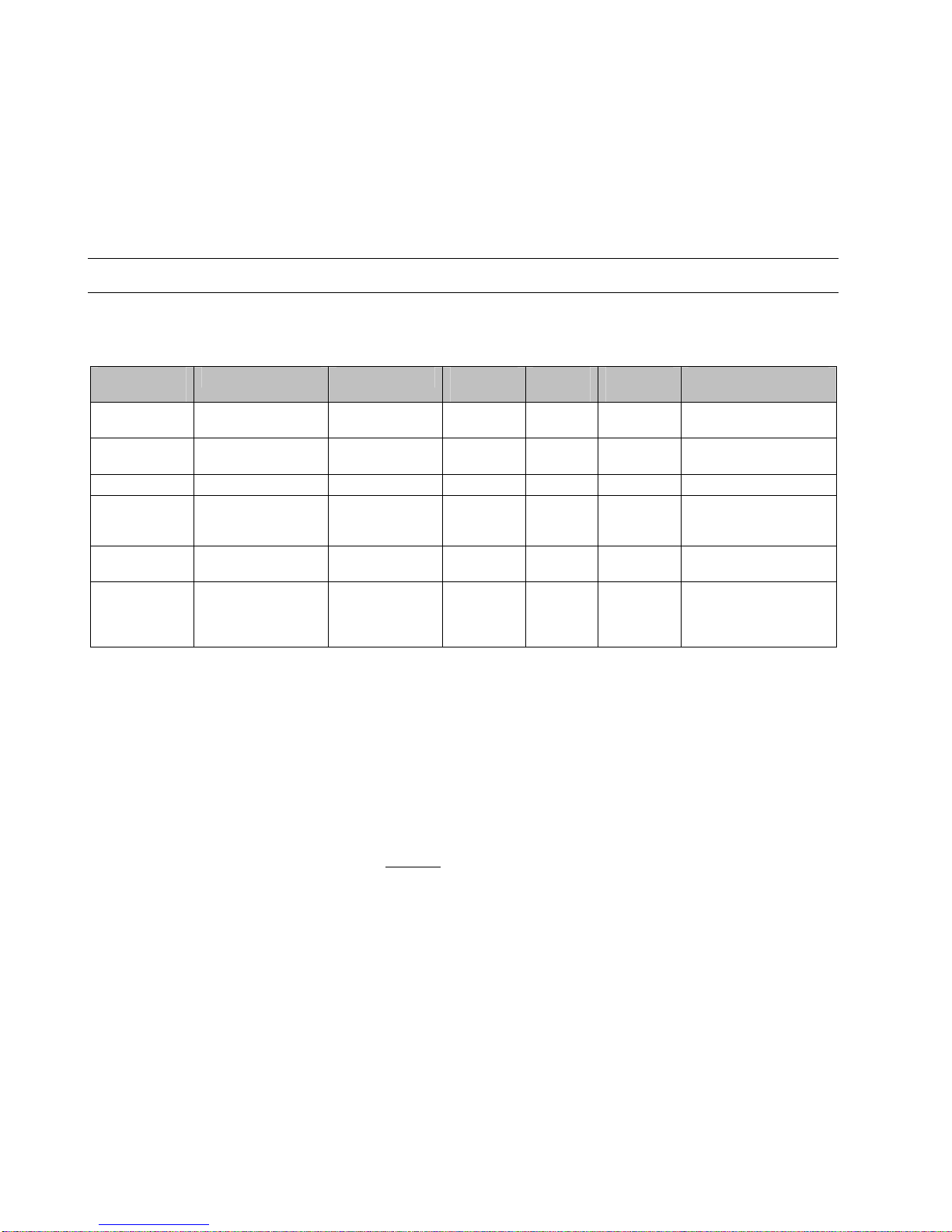
as described in the Version Overview table below.
Order
Number
Standard Upgrade Remote
Sites
Local
Buses
Nodes per
Bus
License Features
CLAR2SL10 x - - 4 10 ARENAEditor,
Max node count: 10
CLAR2SL99 x - - 4 120 ARENAEditor,
Max node count: 9999
CLAR2UL99 x CLAR2SL10 - 4 120 Max. node count: 9999
CLAR2SD99 x - x 4 120 ARENAEditor,
Remote sites,
Max node count: 9999
CLAR2ULD99 x CLAR2SL10 x 4 120 Remote sites,
Max node count: 9999
CLRANGER2 All except:
ARENA Editor,
graphics, global
time program
- via iLON
10 only
- 120 per
iLON 10
-
Order Number Description
CL = CentraLine
AR2 = ARENA Version 2.0
RANGER2 = RANGER Version 2.0
S = Standard version with basic functions including LON driver for local
sites and ARENA Editor
L = CentraLine LON driver
U = Upgrade to unlimited nodes
D = Dial-up
10, 99 = Max. number of nodes, 99 = unlimited but restricted by LON bus to
120
Example:
CLAR10SL = ARENA Standard version with basic functions
including Lon driver for local sites, max. 10 nodes
Page 9
USER GUIDE ARENA/ RANGER
9 EN2Z-0906GE51 R0708
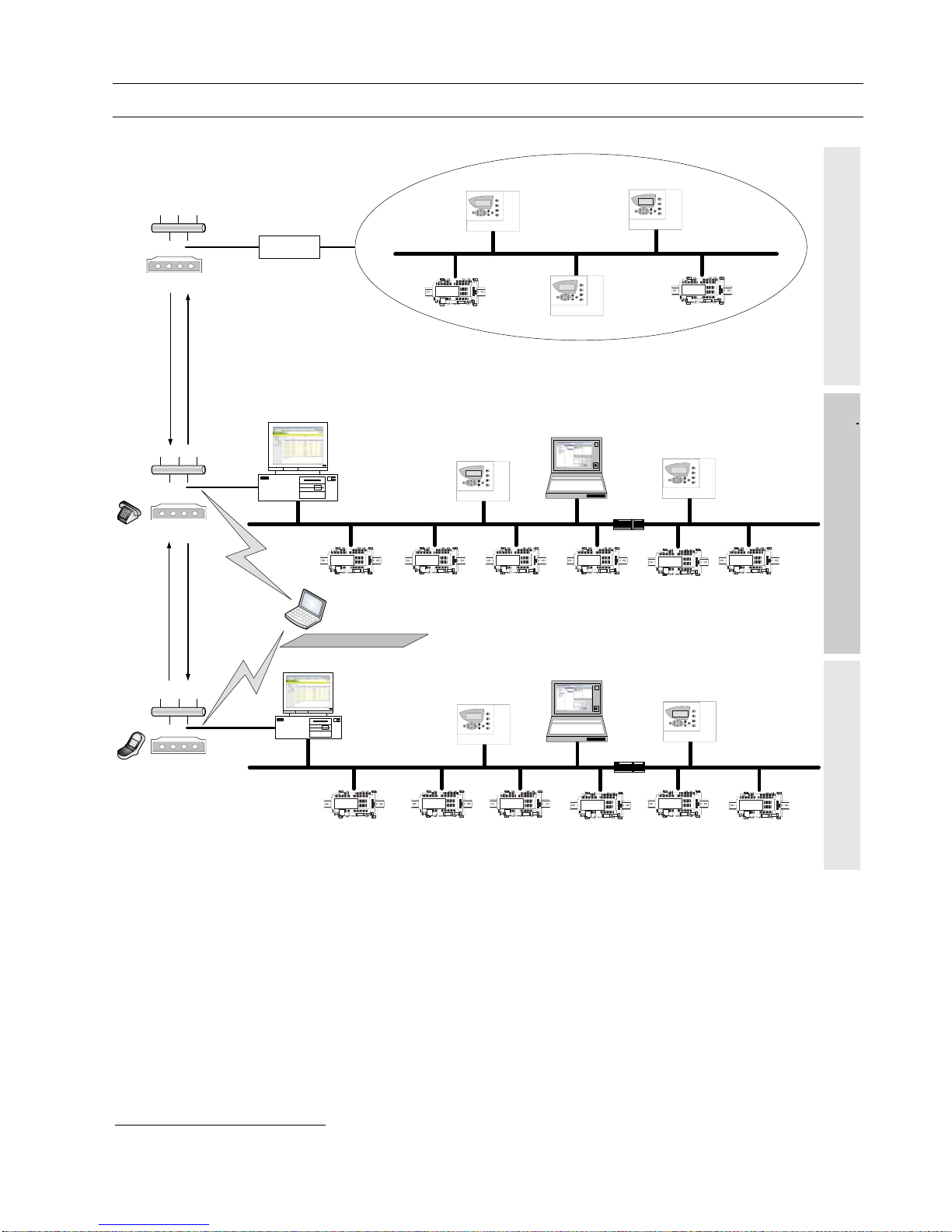
System Architecture
Router**
Modem*
* Not supported in ARENA 2.0
** If more than 60 nodes are present
COACH
Supervisor ARENA
Remote ARENA
Router*
COACH
SERVAL
Modem*
Modem
Dial-In
(e.g. upon user request)
Dial-Out
(Alarms)
Dial-In
(e.g. upon user request)
Dial-Out
(Alarms)
Central Monitoring Site (Home Site) Remote Site (without ARENA)Remote Site (with ARENA)
TIGER / PANTHER
TIGER / PANTHER
TIGER / PANTHER
TIGER / PANTHER
TIGER / PANTHER
TIGER / PANTHER
TIGER / PANTHER
Internet Explorer Access
SERVAL
SERVAL
SERVAL
SERVAL
SERVAL
SERVALSERVALSERVAL SERVAL
SERVAL
SERVAL
SERVAL
SERVAL
iLON 10
LAN
or
or
LAN
or
LAN
Fig. 1: System Architecture with different scenarios
System Scenarios The system graphic shows 3 different usage scenarios for ARENA software:
System with Supervisor ARENA (middle)
ARENA acts as central for the local site and as supervisor for the remote site(s)
System with Remote ARENA (bottom)
ARENA acts as gateway between the supervisor ARENA and the local bus. The
connection can be established via modem
0
*
or any TCP/IP (e.g. ADSL) connection
Stand-alone system without ARENA (top)
No ARENA is available – connection through iLON 10 only
*
Not supported in ARENA 2.0
Page 10

ARENA / RANGER USER GUIDE
EN2Z-0906GE51 R0708 10
All systems can operate individually and independently or together in a complete
system.
Definitions Site
A customer installation of communicating controllers. Equals one COACH project.
Local Site
A site which is connected to an ARENA via one of the following LON interfaces:
• PCC10 PC card
• PCLTA-20 PCI (or PCLTA-21 card)
• Loytec NIC709-USB
• Loytec NIC709-IP
Remote Site with iLON 10
A site that can connect to a supervisor ARENA via remote connection
Remote Site with ARENA
A site with ARENA that can connect to a supervisor ARENA via remote connection.
The connection is established between the ARENAs.
Remote ARENA
An ARENA that “resides” on a remote PC
Supervisor ARENA
An ARENA that can support multiple connected remote and local sites in parallel.
RANGER
Service tool based on ARENA software for remote iLON 10 sites only.
ARENA User Interface via Internet Explorer
Remote or local control via HTTP connection
ARENA Service
Underlying software application automatically started as Windows service.
Dial-in
Dialing occurs from the supervisor ARENA to the remote site. Dial-in is initiated by
the supervisor ARENA.
Dial-out
Dialing occurs from the remote site to the supervisor ARENA. Dial-out is initiated by
a controller (in case no ARENA is available on the remote site) or by the remote
ARENA.
Dial-up
Dial-in or dial-out behavior
Page 11
USER GUIDE ARENA/ RANGER
11 EN2Z-0906GE51 R0708
START ARENA
1. In Windows Start menu, click Programs, then click Centraline and ARENA2
or, click the CL Arena 2.0 icon on the desktop.
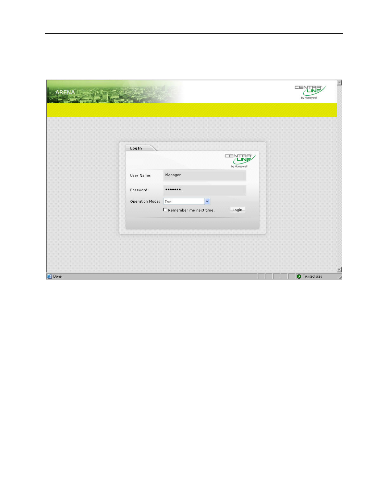
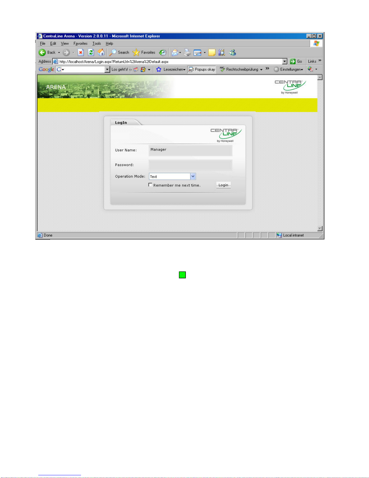
ARENA is started and the ARENA Login screen is displayed.
2. Enter your User Name and your Password.
3. In Operation Mode, select:
Text, if you want to operate ARENA in the common text-based way (Site tree
visible).
In the Text operation mode, the default display shows the following:
– Green banner with the CentraLine logo
– Open tree
– Alarm list
Graphic, if you want to operate ARENA by navigation in referencing and
animated graphics imported via ARENA Editor.
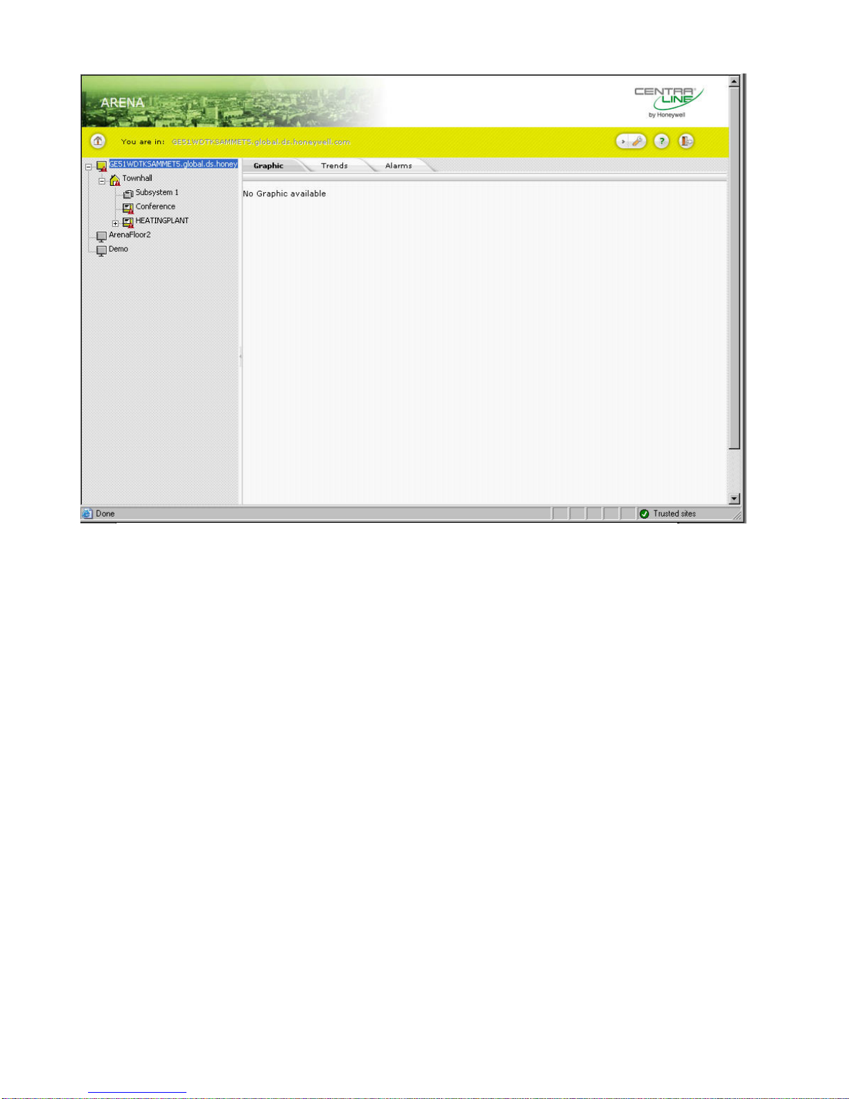
In the Graphic operation mode, the default display shows the following:
– Start graphic
– Default tabs: Graphic, Trends, Alarms
The green banner with the CentraLine logo is permanently invisible.
The tree is invisible and can be displayed by clicking the arrow bar on the
left-handed separator of the main window.
4. Click Login button. ARENA is started and the ARENA main window is
displayed.
Page 12
ARENA / RANGER USER GUIDE
EN2Z-0906GE51 R0708 12
For detailed description of the main window and its functions, please refer to
“ARENA Environment “section.
Page 13
USER GUIDE ARENA/ RANGER
13 EN2Z-0906GE51 R0708
ARENA ENVIRONMENT
Main Screen Description and Basic Functions
Main Screen Description
The Main screen provides two basic panes, the site selection pane, in the following
simply named site tree, and the Information and Editing pane.
Site Tree
The site tree on the left displays all sites (local or remote) of ARENA in a
hierarchical tree structure. The tree structure varies depending on the operating
mode (online=connected, offline=disconnected) and on the system architecture that
is, on whether you are on a local ARENA connecting to a local site or to a remote
site with/without ARENA, and other scenarios.
Page 14

ARENA / RANGER USER GUIDE
EN2Z-0906GE51 R0708 14
Fig. 2. Site Display Modes in Tree
Depending on the current operating status (online= connected) or (offline=
disconnected), the sites are indicated differently. A connected site is displayed in full
color; a disconnected site is displayed in transparent color. A red triangle with
exclamation mark may appear which indicates an unacknowledged alarm.
Information and Editing Pane
The right pane can show:
• the properties of the selected item in the tree, which may look different
depending on the selected item.
• an opened menu, e.g. ´User`, selected from the Configuration menu
.
Page 15
USER GUIDE ARENA/ RANGER
15 EN2Z-0906GE51 R0708
Fig. 3. Example: Tree Item display in the Information and Editing pane
Fig. 4. Example: Menu display in the Information and Editing pane
Sizing the Pane Displays
The size of the pane display can be varied by moving the separator horizontally to
the left or right. ARENA will remember the corrected width when coming back or
restarting the software.
Page 16

ARENA / RANGER USER GUIDE
EN2Z-0906GE51 R0708 16
Collapsing/Expanding the Site Pane
The site pane can be collapsed (hidden) by clicking the arrow bar in the middle of
the separator. The hidden site pane can be expanded (made visible) by clicking on
the arrow bar on the left-handed separator in the main window.
Tree Navigation
You can navigate through the tree by clicking on tree items, or by clicking the plus/minus icons at the tree items.
Viewing and Editing Information
To view or edit data and properties of an item, select an item by clicking on the item
in the tree, or by selecting the menu in the Configuration menu.
In the toolbar, the path of the selected item is displayed
Example:
You are in: GE51WDTKSAMMET.global.ds.honeywell.com » Configuration » User
Administration.
On the Information and Editing pane, the corresponding data and properties of the
selected item/menu are displayed.
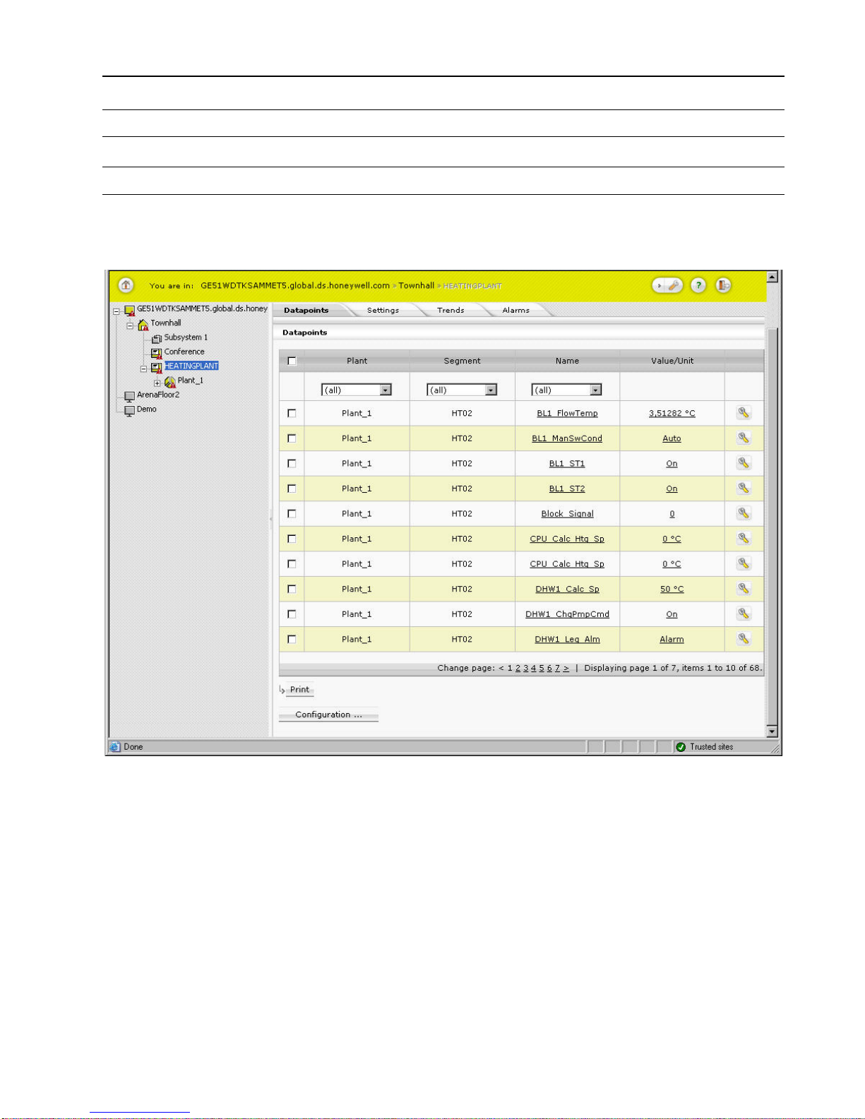
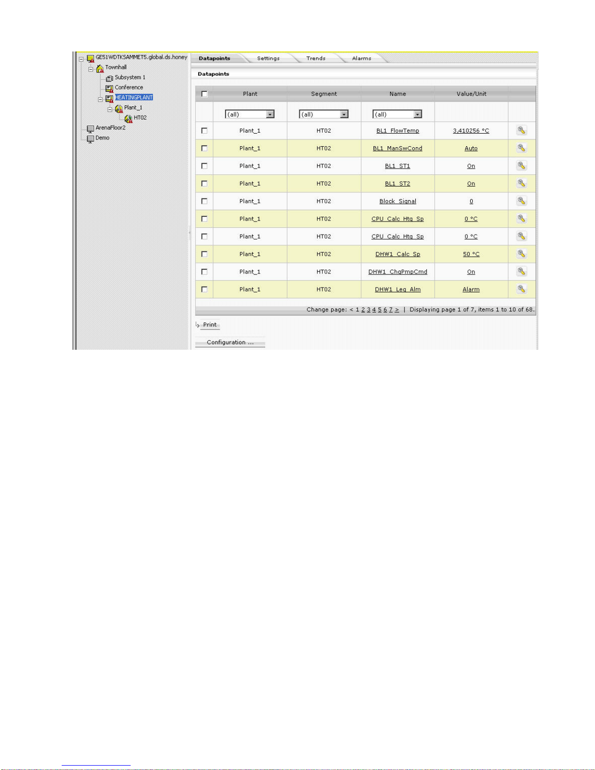
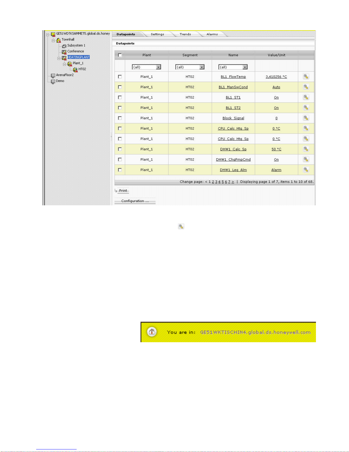
Example: Datapoints display in the Information and Editing pane for a
selected (PANTHER) controller.
Page 17
USER GUIDE ARENA/ RANGER
17 EN2Z-0906GE51 R0708
To edit item properties, select tree item, e.g. HEATING PLANT, and then select tab,
e.g., Datapoints, and click item you want to edit.
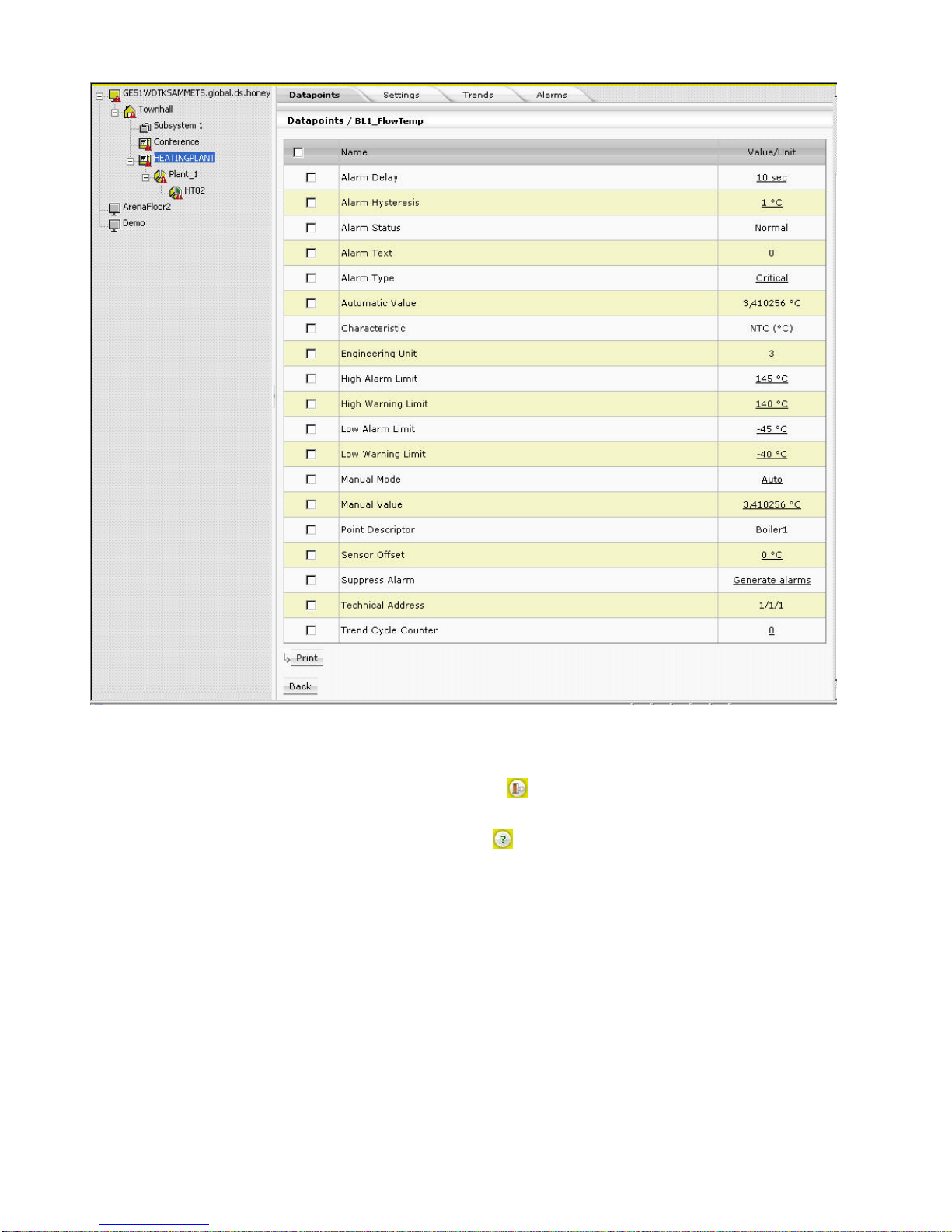
Example: Datapoint editing in the Information and Editing pane for a selected
datapoint of a PANTHER controller.
Page 18
ARENA / RANGER USER GUIDE
EN2Z-0906GE51 R0708 18
Values can be edited by clicking on the corresponding value which
opens a dialog for editing the value.
Logout
By clicking the Logout icon , you can logout.
Context Sensitive Online Help
Clicking on the Help icon
displays the ARENA online help in PDF format.
Basic Functions
The properties of a selected item in the tree, for example, a PANTHER controller,
are displayed on tabs on the right pane.
Page 19
USER GUIDE ARENA/ RANGER
19 EN2Z-0906GE51 R0708
Depending on the user privileges, data can be modified by clicking the appropriate
buttons, such as Print, Save, Delete, etc, or by using allocated icons, for example
the Configure icon of a datapoint.
An underlined item in a list indicates that this entry links to a further dialog showing
more details of the item.
By clicking on the entry, you can edit details of the selected item.
For each toolbar button, a tool tip is provided which will be visible while the cursor
remains over the button for a few seconds.
Updating Data (Refresh)
Data updates occur automatically and periodically. You can manually refresh data
by using the Internet Explorer Refresh function.
Leaving Configure Menu
To switch back from within a view of the Configure menu to the site tree, click on the
HOME button.
Saving Data
Saving and discarding changed data is handled by using the following buttons
(dependent on the dialog):
OK
Saves changes done in the current dialog
CLOSE / CANCEL
Discards changes done in the current dialog
Page 20
ARENA / RANGER USER GUIDE
EN2Z-0906GE51 R0708 20
Further Button Functions
NEW / GO / SCAN / DELETE / others
Those kind of specific buttons perform functions as the button name indicates in its
functional context.
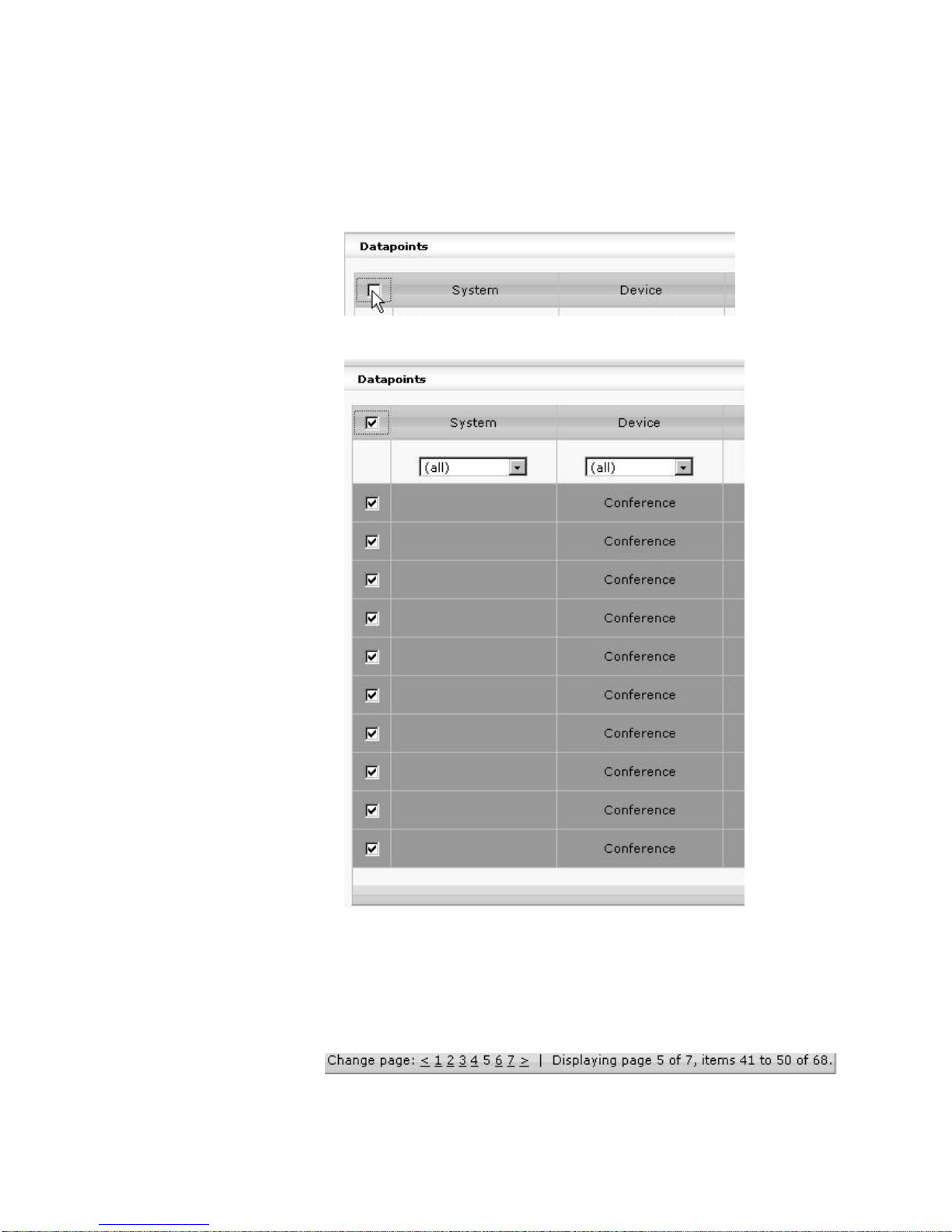
Multiselection of Items
Clicking the checkbox in the title line of a list,
Simultaneously selects all entries in the list.
In particular dialogs, multiple items can be selected by using the SHIFT or the CTRL
key simultaneously with the mouse clicking.
Page Selection and List Display Configuration
Page selection
At the bottom of each list, the number of pages and number of list items, the
currently displayed page and list items are shown.
By clicking on a specific page number you can display a certain page and/or by
using the ≤ ≥ icons you can scroll through the page list.
Page 21
USER GUIDE ARENA/ RANGER
21 EN2Z-0906GE51 R0708
List Display Configuration
A list configuration, for example of a datapoints list, always applies to all lists of the
same kind (in this case all datapoints list) on the same level (site, device, plant,
segment). The appearance of a list, for example, a datapoints list, can be defined by
configuring the following:
• Display columns
Defines, which columns are displayed and in which order the columns are
displayed
• Sort order
Defines the default sort sequence (ascending or descending) within a column
• Default filter
Defines which filter is used by default for the list display
NOTE: The filter definitions apply to all local users of the ARENA.
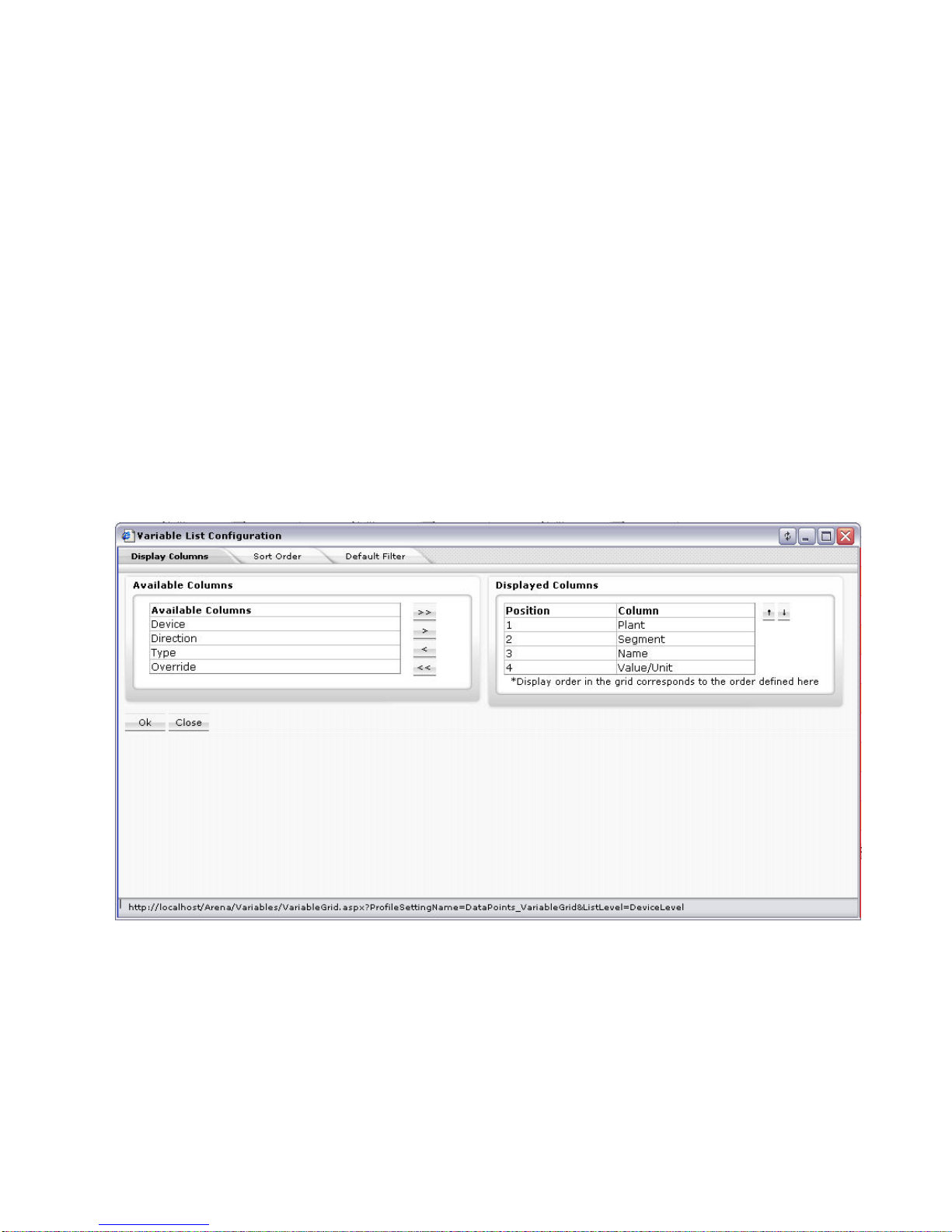
1. At the bottom of the list, click the Configuration button.
The Variable List Configuration dialog box displays.
2. To configure the columns displayed and their sort sequence, click the Display
Columns tab.
Under Available columns, all columns that can be displayed at maximum are
listed. Under Displayed Columns, all currently displayed columns are listed. The
column display will be configured by moving the columns between the Available
Columns and Displayed Columns tables using the angle brackets under
Available Columns. The sort sequence of the displayed columns will be
configured by using the upward and downward buttons under Displayed
Columns.
3. To select the columns to be displayed and their sort sequence, move columns
between the tables and determine sort sequence by doing one of the following:
a. To move single column(s),
In the Available Columns list or in the Displayed Columns table, highlight the
columns to be moved. Multiselection by using the CTRL key is possible.
b. Click the single angle bracket button of the desired direction.
Or,
c. To move all column(s) in one step,
Click the double angle bracket button of the desired direction.
d. To set the sort sequence, that is, the position of the columns within the
displayed list, highlight the column in the Displayed Columns table.
Multiselection by using the CTRL key is possible.
Page 22
ARENA / RANGER USER GUIDE
EN2Z-0906GE51 R0708 22
e. Click the upward or downward buttons.
4. Click the OK button so save settings or continue with:
a. Setting the sort order within a column and/or (step
15)
b. Setting the default filter display (step 17).
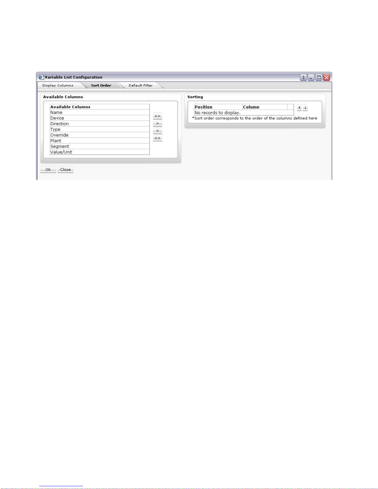
5. To set the sort order within a column, click the Sort Order tab.
Under Available columns, all columns of which sort order can be set, are listed.
Under Sorting, all columns and their current sort sequence are listed.
NOTE:
By default, all columns are sorted ascending.
The column selection for setting (changing) the sort sequence is done by
moving the columns between the Available Columns and Sorting tables using
the angle brackets under Available Columns. The sorting priority within the list
will be set by using the upward and downward buttons under Sorting.
a. To move single column(s),
In the Available Columns list or in the Sorting table, highlight the columns to
be moved. Multiselection by using the CTRL key is possible.
b. Click the single angle bracket button of the desired direction.
Or,
c. To move all column(s) in one step,
Click the double angle bracket button of the desired direction.
d. To set the sorting priority, highlight the column in the Sorting table.
Multiselection by using the CTRL key is possible.
e. Click the upward or downward buttons.
f. For each column, select the sort sequence, Ascending or Descending from
the drop-down listbox.
6. Click the OK button so save settings or continue with:
a. Setting the default filter display (step
17).
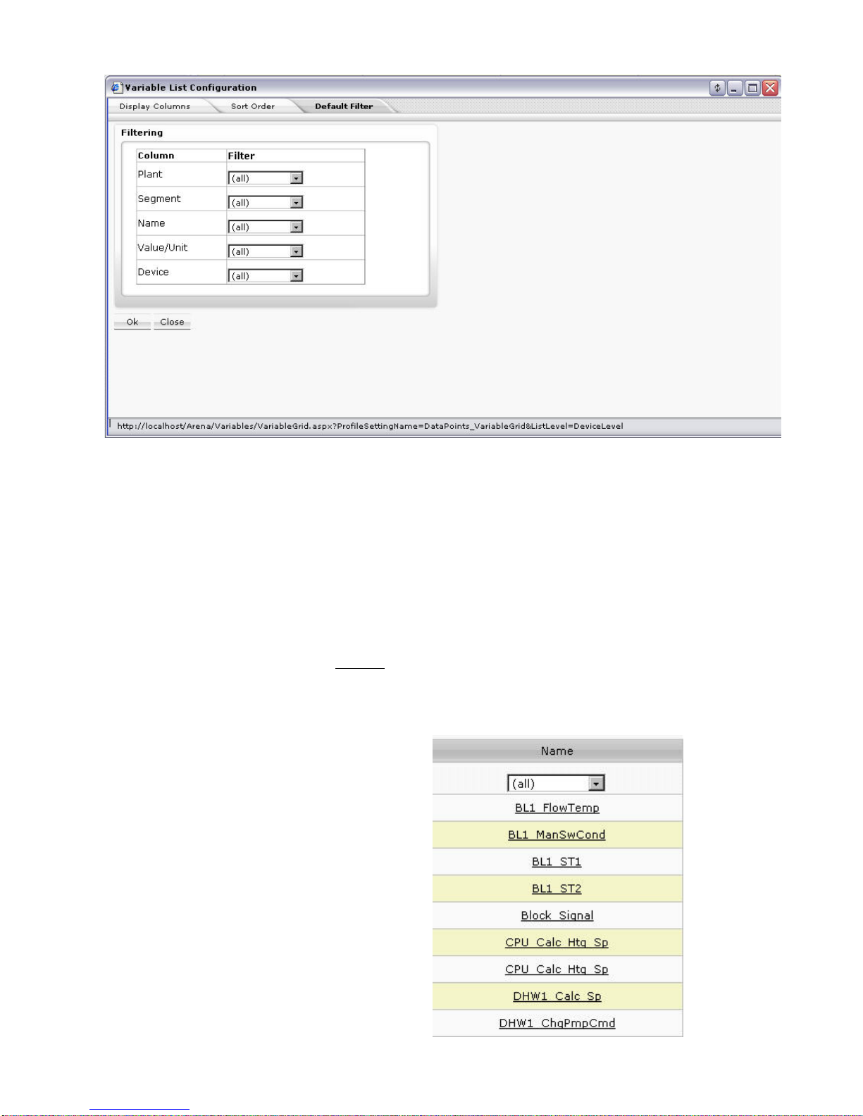
7. To set the default filter to be used when displaying a list, click the Default Filter
tab.
Page 23
USER GUIDE ARENA/ RANGER
23 EN2Z-0906GE51 R0708
Under Filtering, all displayed columns of the list and their current filter setting is
shown. By default, no particular filter is used (All), that is, all items are displayed.
Depending on the column property, e.g. Name or Value/Unit, you can select
different particular items which you want to filter for display. You can create a
new filter which can be selected here after it has been created elsewhere (see
“Create New Filter” section).
a. In the Filter column, select filter from the corresponding drop-down listbox.
8. Click the OK button so save settings.
Apply Filter for Display
You can use filters for displaying particular list items of a list.
The filter applied to a list is temporary. The filter setting will sustain until a different
pane is selected.
Example:
When applying a filter to a datapoints list, it will remain as long as datapoint panes
are opened. After selecting, e.g. ´Time Programs`, the filter will be deleted.
In a list, for example the datappoints list, by default, no filter is applied to a column
which is indicated by the entry ´(all)` in the field below the column title.
Page 24

ARENA / RANGER USER GUIDE
EN2Z-0906GE51 R0708 24
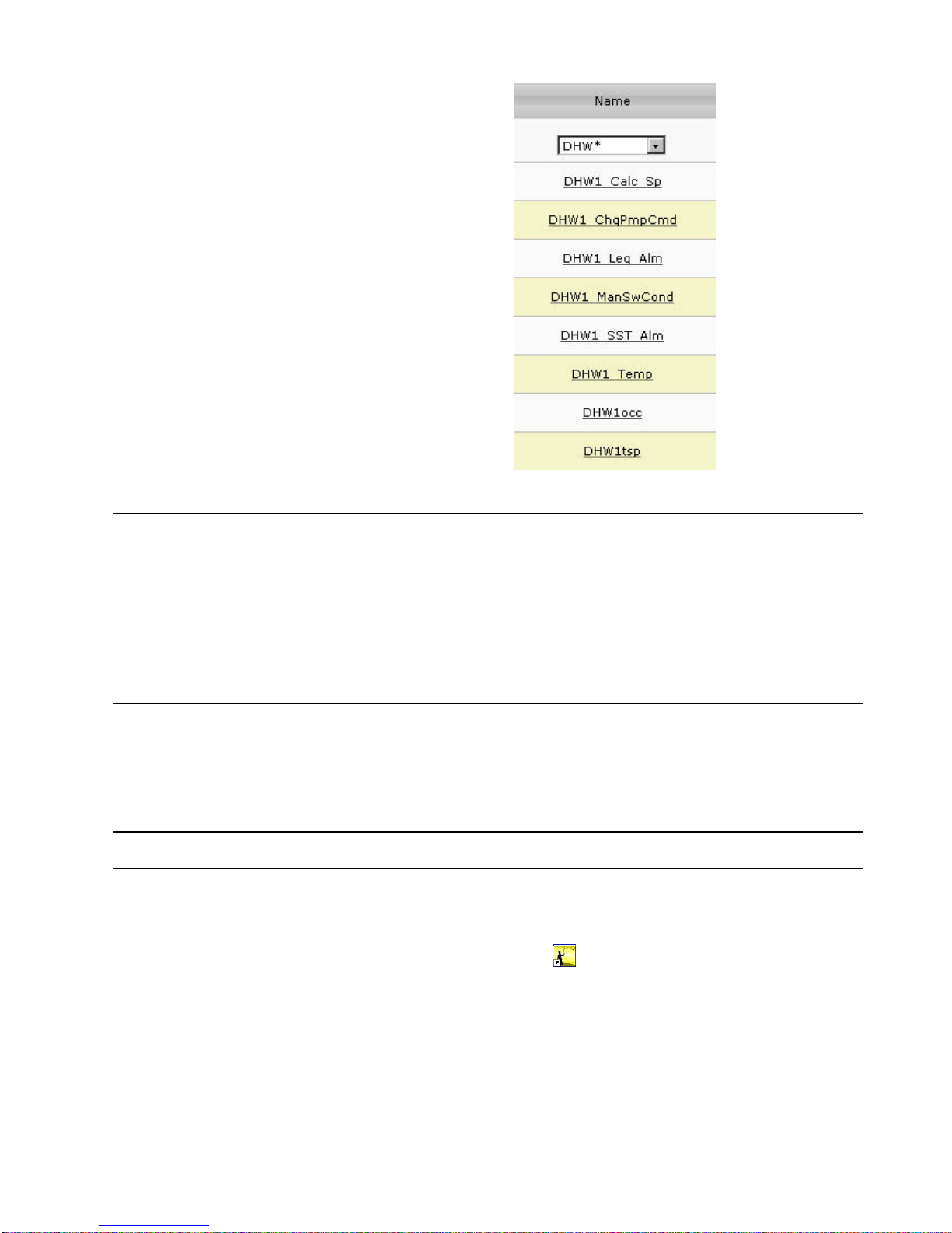
1. To apply a filter, click in the field and do one of the following:
a. select the filter criterion, for example, ´Digital` in the Type column if you want
to display digital datapoints only.
Or,
b. if no filter criteria are available, click New Filter
c. In the Select Wildcard dialog box, enter the Filter string by using the asterisk
and click OK button.
For example, the filter string ´DHW*` displays only datapoints of which name
starts with ´DHW`.
Page 25
USER GUIDE ARENA/ RANGER
25 EN2Z-0906GE51 R0708
Usage of Illegal Characters
It is forbidden to use the following characters when working with ARENA:
• Slash character ”/” in alias names
• Special characters and Umlauts Ä, Ö, Ü, ä, ö, ü in site names when creating
sites. After creation of the site, you can change a site name in the tree using
these characters.
Using any of these characters may result in an unexpected behavior of ARENA.
Date and Time Format Display Settings
The display of date and time as it used in various lists within ARENA depends on
the language settings for the browser. To get the desired format displayed, set the
corresponding language to the highest priority as desribed in the “Internet
Explorer/General” section of the ARENA Installation Guide EN1Z-0906GE51.
ARENA APPLICATION
The ARENA application includes the following main software components:
ARENA user interface
The ARENA user interface for viewing and operating ARENA is invoked by clicking
the CL Arena 2.0 program icon
on the desktop. This will start the Internet
Explorer.
Page 26
ARENA / RANGER USER GUIDE
EN2Z-0906GE51 R0708 26
ARENA Service
The underlying software of ARENA is the service, named ARENA service or simply
service. This service is accessible in the system tray and is indicated there as
square service icon
. The actual operating mode of the service is indicated by
different colors of the service icon:
• Green = Service is running
• Red = Service has stopped
• Yellow = service being started or stopped
Via right mouse-click on the service icon, the following basic functions, are available:
NOTE: As long as the service is running, all online changes will be stored to the
ARENA database (e.g. trend data will be collected) even if the ARENA user
interface is not started.
About
Shows the version information of ARENA.
Backup / Restore
Backups / restores the complete ARENA database including all settings and
customized configuration
Editor Export
Exports the complete site information into a file that is needed to make assignments
for a graphic via the ARENA Editor.
Licensing
Invokes the licensing dialog for registering ARENA. The service is restarted after a
license has been changed.
Page 27

USER GUIDE ARENA/ RANGER
27 EN2Z-0906GE51 R0708
Service
Starts / stops ARENA and shows its status information (Running, Stopped). In
addition, an optimize disc space command is available.
Exit
Stops the service and shuts down ARENA.
Show ARENA Version Information
1. In the system tray, right-click on the Service icon.
2. In the context menu, click About.
RESULT: The About CentraLine ARENA information box displays showing
the actual used version of ARENA.
3. After you have read the version information, click OK.
Backup / Restore
Backing up a project copies the ARENA database information in one single file to a
backup directory. Restoring the database retrieves a copy of the database to place it
in the PC. This procedure is useful if the PC files are corrupt or if changes were
made that need to be erased.
Backups and Restores can only be done locally and complete. It is not possible to
backup/restore parts of the ARENA database because “large info” as trends and
alarms can be deleted from the backup before doing it or after restoring it. Backups
contain the graphic pages too. Backup/Restores via Web are not possible.
Data can be restored from a previously back upped database. If a backup is done
with a previous ARENA 2.xx version, it will be automatically upgraded.
NOTE: This Backup / Restore function restores ARENA data only but not controller
data like time programs and settings.
1. In the system tray, right-click on the Service icon.
2. In the context menu, click Backup / Restore.
3. For backups, click the Backup tab, for restores, click the Restore tab.
4. Browse to the folder where you want to save/open the database.
5. For backups, click Backup button, for restores, click Restore button.
6. In case a message box displays, confirm the message by clicking OK.
NOTE: In order to perform an ARENA database backup, it is necessary to be
logged onto the PC with administrator privileges.
NOTE: When performing a backup, the ARENA service is stopped (red color of
service icon) and restarted (green color of service icon) after finishing the
backup. During the backup phase, the ARENA user interface cannot be
operated.
Export Data to ARENA Editor
You can export the complete site structure (incl. time programs) from a running
ARENA into a file.
Then, the file can be opened in the ARENA Editor to allow picking the information
for the data bindings. The names of the items (e.g. sites, controllers, datapoints,
NVs, etc.) are displayed in a tree as in ARENA and can be picked. Changing of alias
names in ARENA will not be reflected in the graphics and after the renaming in
ARENA, the data binding will still work.
1. In the system tray, right-click on the Service icon.
2. In the context menu, click Edit or Export.
Page 28

ARENA / RANGER USER GUIDE
EN2Z-0906GE51 R0708 28
3. Right to the File field, browse to the folder where you want to save the export
file.
4. Click Export button.
5. Click Close button.
Manage Library
With this function, you can manage the library content and the view of the library
components (configurable standard applications, room controls, segments).
To start and work with the library manager, do the following:
1. In the system tray, right-click on the Service icon.
2. In the context menu, click Manage Library. The Library Manager dialog box
displays.
2. Under List of segments in Library, for each library component, the following
information is displayed:
– Identifier (for internal use only)
– Segment Type
Name of the library component as displayed in the library view
– Family
– Family which the component belongs to. The family name determines the
folder in which the component is inserted.
– Version
Version of the library component. In COACH multiple versions of the
same library component can be handled simultaneously.
– File
File name (.DLL).
3. To determine which library component is visible or hidden in the library view,
check the checkbox in the first column for a library component you want to
shown and uncheck the corresponding checkbox if you want to hide the library
component.
4. To import new or other segments via .CSL file, click Bro wse and select the
CSL file. Then click Open. CSL files are provided by Honeywell CentraLine and
Page 29

USER GUIDE ARENA/ RANGER
29 EN2Z-0906GE51 R0708
can include new library components or segment updates of existing library
components.
NOTE: You cannot create CSL files by your own.
After the import is finished all library components, included in the CSL file, are
added to the list.
5. Apply step 3. for the imported library components.
6. Click Save, and then click Close.
Licensing
1. In the system tray, right-click on the Service icon.
2. In the context menu, click Licensing.
For detailed information on Licensing, please refer to the ARENA installation
guide EN1Z-0906GE51.
Start / Stop Service
1. In the system tray, right-click on the Service icon.
2. In the context menu, hover over Service, then click Start if the service has
stopped and you want to restart the service, or, click Stop, if you want to stop a
running service.
The Service icon turns to red when the service has been stopped and to green
when the service has been started.
3. To view the current operating status, click Status in the Service menu. The
status is displayed in the Service dialog box. You can still Stop and Start the
service here. Click Stop or Start button if desired.
4. To optimize disc space, click Status in the Service menu, then click Optimize
button in the Service dialog box.
NOTE: As long as the service is running, all online changes will be stored to the
ARENA database (e.g. trend data will be collected) even if the ARENA user
interface is not started.
Exit
1. In the system tray, right-click on the Service icon.
2. In the context menu, click Exit.
The Service icon is no longer available, other when stopping the service. To
redisplay the service icon, click Start>Programs>Autostart>CL Arena Monitor.
ARENA Configuration Menu
Several functions for basic configuration settings (e.g. user administration, password
settings, etc.) are provided in the ARENA configuration menu. The access to the
configuration menu depends on the user privileges. The following functions are
available:
Site
Provides site management functions such as creating, editing and deleting sites.
User
Provides the user administration for creating, editing, and deleting users.
Alarming
Provides alarm forwarding functions.
Page 30

ARENA / RANGER USER GUIDE
EN2Z-0906GE51 R0708 30
Password
Allows the user to change its own password.
Trending
Provides basic pre-setting functions for executing trends.
NOTE: To exit the configuration menu, click the Home button
.
USER ADMINISTRATION
The user administration is used for creating users and assigning particular user
privileges (roles) to the users. Administration also includes editing and deleting of
users.
Roles and Privileges A role determines the privileges that the user will have when working with ARENA.
A role with its determining privileges is pre-defined and cannot be changed. User
privileges of a certain user can be changed by assigning another role. In ARENA,
the following role – user privileges combinations are assignable to users:
Role User Privileges
Manager Service privileges plus:
Creation, edition and deletion of users with lower roles.
Service Keeper privileges plus:
Changes of datapoint attribute, parameters, network variables and
time programs. Adjustments for installation and scanning. Alarm
acknowledgement. Creation, edition and deletion of users with
lower roles
Keeper Viewer privileges plus:
Time program changes (incl. setpoints). Alarm acknowledgement.
Creation, edition and deletion of users with lower roles
Viewer Viewing statistics and reports generation.
As the table shows, the predefined roles are arranged hierarchically and the
sequence with descending priority is as follows:
• Manager
• Service
• Keeper
• Viewer
Example:
When assigning the ´Service` role to a user, a user having a role below ´Service`,
for example ´Keeper`, is not able to change datapoint attributes. A user having a
role equal to or higher than ´Service`, for example ´Manager` is able to change
datapoint attributes.
The table shows, that the logged user can create, modify and delete users with a
role lower than its own.
User Profile For each user within a project, a user profile with the following properties will be
created:
• User name
• Role (User privilege)
• Password
• Access Restrictions (definable per site local or remote)
A user is identified by its user name.
One of the predefined roles will be appropriately assigned to the user (name). This
assignment automatically determines the user privileges, which the user are allowed
to execute in the ARENA he is logged in. All users having a role higher than or
equal to the assigned role will have this user privilege enabled in ARENA, all others
will not.
Page 31

USER GUIDE ARENA/ RANGER
31 EN2Z-0906GE51 R0708
In addition, a password for each user must be issued for secure operation of
ARENA.
Finally, for comfortable remote operation, a user can have an Auto-Logon property
assigned that allows logging into the remote site without entering Login name and
password again.
Login, Information Access and
Password Handling When entering a site, you must login with user name and password. After logged in,
you will see all information that you have access to, based on your role. When you
click on items that are unavailable due to your role (e.g. when a service user selects
configuration), you are asked for logging in again.
NOTE: Usually, ARENA will not display items/functions that are not available for
the current user role. However, in graphics there may be links that require
a higher user level (in this case, a login is forced). Also, a login is forced
when you enter a direct link to a page in the browser:
You have not to login again, even when going to another site (e.g. to an ARENA
remote site), as long as on that site a user with the same user name and password
exists.
You can change your own password without invoking the User Administration.
IMPORTANT
It is strongly recommended to delete default users or change the default
password of each role since the password reads the same as the
corresponding role.
Invoke User Administration
1. In the tree, select the site, on which you want to administer users, for example to
create new users.
NOTE: The user administration can only be invoked from users having
privilege level ´service` or higher.
2. Hover the cursor over the Configuration menu icon
and click User in the
configuration menu.
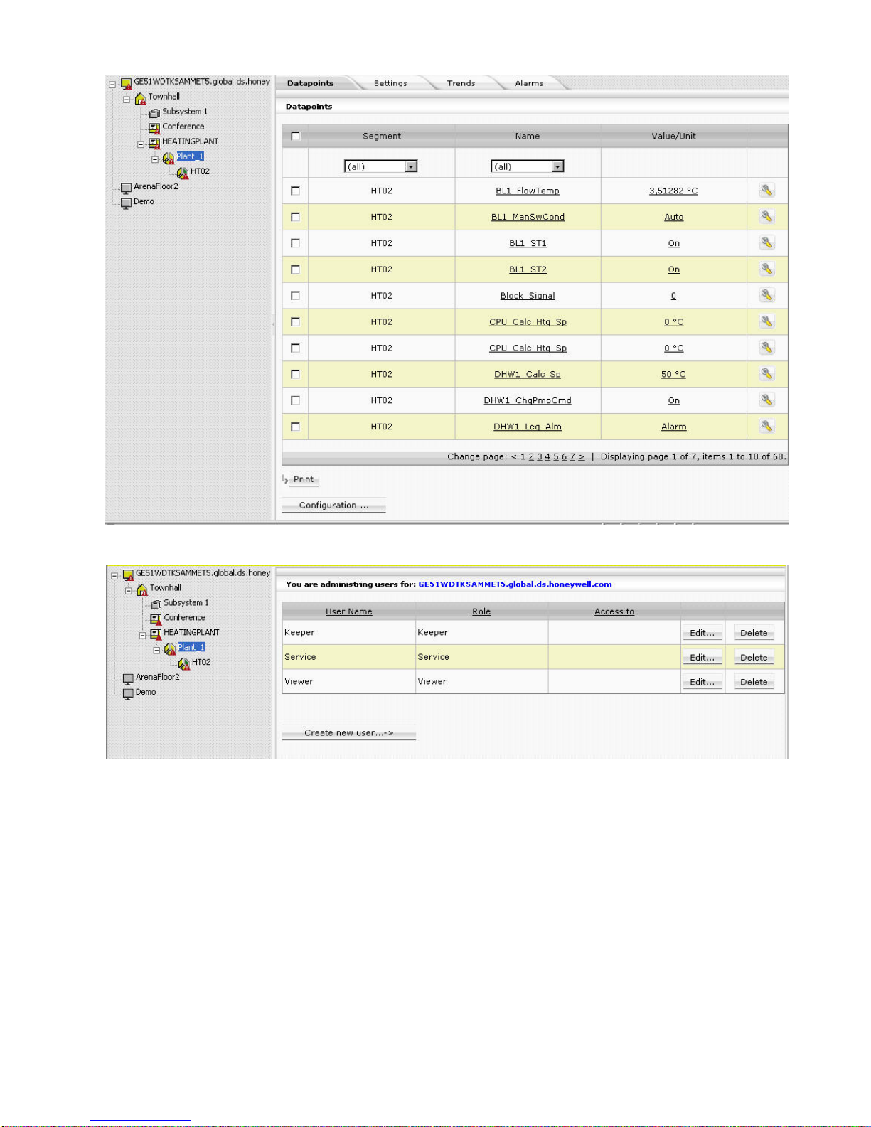
RESULT: The Users List is displayed. Each user is displayed by name, role,
and access type. An empty cell in the Access to column means that
the listed user has access restrictions which can be seen when
clicking on the Edit button. By default, every default user has no
access restrictions as indicated by an asterisk.
You can create new users and edit and delete users.
Page 32

ARENA / RANGER USER GUIDE
EN2Z-0906GE51 R0708 32
Create New User
1. Click Create new user button.
RESULT: The Edit/Create new user dialog is displayed.
Page 33

USER GUIDE ARENA/ RANGER
33 EN2Z-0906GE51 R0708
2. In User Name, enter the user name.
3. In Password, enter the password.
4. In Password, confirm the password by entering the same password.
NOTE: When creating sites that use incoming connections, It is strongly
recommended to change the password of default user names such
as manager, keeper, etc. which by default reads the same as the
user name.
5. In Role, select the role for the user.
6. In Comment, enter a comment if desired.
7. Under Access Restrictions, select from:
No access restrictions
The user has access to all sites on which he already exists and which are
displayed in the site tree including remote ARENAs. When a new site is created,
the user will automatically have access to it.
Grant access only to
The user has restricted access, that is, the user can access only particular sites.
In the list below, all sites are displayed that are known on the site selected in the
tree. These sites can be:
• Local sites
• Remote sites via iLON 10
• Remote ARENAs
Sites to which the user has no access are disabled (gray). When the user
administration is invoked for a remote ARENA selected in the tree, the users will
be administered for that site. Then the sites of the remote ARENA are listed
here.
8. In the list below, select the site(s) which the user should have access to by
clicking the corresponding checkbox(es).
9. To allow the user (with or without restrictions) entering a remote site without
entering user name and password again (Auto-Logon User), click the Edit
button.
10. In the password dialog, enter the user name and password for the user. If a
password has been issued once, enter it in Old password. In New password,
enter a new password.
NOTES: Auto-Logon users can be created only for connections to remote
ARENA sites. The user must exist on the remote site and user
name and password must match the entries you enter here.
11. In the password dialog, click OK button. The user is created and displayed as
Auto-Logon user in the column of the same name.
Page 34

ARENA / RANGER USER GUIDE
EN2Z-0906GE51 R0708 34
12. Click Save button.
RESULT: The created user is displayed in the Users list.
Edit User
1. In the Users list, click on the user name you want to edit, then click the Edit
button in the corresponding line.
RESULT: The Edit/Create new user dialog is displayed.
Page 35

USER GUIDE ARENA/ RANGER
35 EN2Z-0906GE51 R0708
2. Edit desired properties. For description of the properties, please refer to the
“Create New User” section.
3. Click Save button.
Delete User
1. In the Users list, click on the user name you want to delete, then click the Delete
button in the corresponding line.
RESULT: The user is deleted and removed from the list.
Change Password
IMPORTANT
It is strongly recommended to delete default users or change the default
password of each role since the password reads the same as the
corresponding role.
Page 36

ARENA / RANGER USER GUIDE
EN2Z-0906GE51 R0708 36
1. Hover the cursor over the Configuration icon and click Password in the
menu.
2. In Old password, enter the current password.
3. In New Password, enter the new password.
4. In Repeat new passw o rd, enter the new password.
5. Click OK button. The password is changed.
NOTE: You can only change your own password.
Page 37

USER GUIDE ARENA/ RANGER
37 EN2Z-0906GE51 R0708
SITE MANAGEMENT
Local Site Support ARENA supports the connection to up to 4 local sites.
Remote Site Support ARENA supports remote sites, which are connected through iLON 10 or through
another remote ARENA. That ARENA is called Supervisor ARENA.
Ranger supports remote sites, which are connected through iLON 10 only.
iLON 10 Sites via LAN ARENA supports remote sites, which are connected through iLON 10. Only one
ARENA can be connected at the same time to one iLON 10.
If a connection between an ARENA and an iLON is established, a second ARENA
cannot connect to the iLON 10. This is indicated by a message.
ARENA / ARENA via Mo d em
1
*
Connection is only possible if an incoming connection is defined beforehand
manually in Windows.
Example:
ARENA A -> ARENA B connection via modem
On ARENA A, configure a remote ARENA B. On ARENA B do nothing.
Expectation is that the user does not need to configure on Arena B explicitly an
incoming connection.
Connection Types Arena can establish a remote connection either via modem dialing or LAN
connection. ARENA differentiates between these two connection types. Depending
on the infrastructure, ARENA supports opened connections in parallel.
• Modem connection
After ARENA restart, ARENA will not automatically establish a connection to a
remote site.
• LAN connection
After ARENA restart, ARENA will automatically establish a connection to all
reachable remote sites
CAUTION
Two ARENAs are only allowed to be connected via one connection type,
LAN or modem. That is, it is not allowed to connect two ARENAs to each
other in multiple ways, for example, via LAN and modem.
ARENA 1
ARENA 2
ARENA 3
Modem
LAN
LAN
Connect Sites You can manually connect to a site. The manual connection can be established via
right-click on the site in the site tree.
Disconnect Sites You can manually disconnect ARENA from a local or remote site and disconnect all
local or remote connections.
Automatic Disconnection of Modem Sites
ARENA supports an automatic disconnect mechanism for sites connect via modem:
After a definable time, ARENA pops up a dialog that asks you if you want to remain
connected. You can decide whether to “remain connected for another X minutes” or
to disconnect. X is the predefined connection time, which is changeable in the
popup dialog. If you do not react for a defined reaction time (e.g. 60 s), the
*
Not supported in ARENA 2.0
Page 38

ARENA / RANGER USER GUIDE
EN2Z-0906GE51 R0708 38
connection is automatically terminated. Automatic disconnection prevents “forgetting
to close a connection”. It is used for modem connections only.
NOTE: If a remote site is disconnected, the supervisor ARENA has a time out of
up to 2 minutes before the tree gets refreshed to indicate offline state.
Site Combinations The max. of 100 sites can be arranged in one supervisor ARENA system. In the
following several major site combinations are described briefly:
• ARENA Æ iLON 10 (via Modem)
LON Bus
SERVALSERVALSERVAL
PANTHER / TIGER
iLON 10
Supervisor
ARENA
Modem
Fig. 5. Site Combination ARENA Æ iLON 10 (via Modem)
– Remote maintenance and alerting (alarms)
– Dial-up always occurs manually. Dialing will be automatically interrupted
after 20 min.
– In case of iLON 10 dial-up, dialing will be automatically interrupted after
the alarms has been sent
– During connection, live trend is possible
– PANTHER / TIGER alarms cause the iLON 10 to dial-up
– SERVAL alarms are generated and displayed by ARENA during
connection.
– If there is a connection to the remote site, alarms will be forwarded
• ARENA Æ iLON 10 (via LAN)
LON Bus
SERVALSERVALSERVAL
PANTHER / TIGER
iLON 10
Supervisor
ARENA
LAN
Fig. 6. Site Combination ARENA Æ iLON 10 (via LAN)
– Remote maintenance and alerting (alarms)
– After ARENA is started, a connection to all participants will be
established which can be reached via LAN, and then the alarms will be
sent.
– Historical trend und live trend is possible
– Automatic re-connection after LAN disconnection
• Supervisor ARENA Æ ARENA (via LAN, local bus only)
LON Bus
SERVALSERVALSERVAL
PANTHER / TIGER
Supervisor
ARENA
Remote
ARENA
LAN
Fig. 7. Site Combination ARENA Æ ARENA (via LAN)
– Example for a supervisor ARENA which centrally connects data of one or
multiple remote ARENAs.
– Remote maintenance
– Connection via modem oder LAN
– Alarming
Page 39

USER GUIDE ARENA/ RANGER
39 EN2Z-0906GE51 R0708
– Settings such as graphic, alias, etc. done in the supervisor ARENA apply
only to the supervisor ARENA itself and are independent of settings done
in a local ARENA
– Online value changes through Remote control: last wins
– Trending
• Supervisor ARENA Æ ARENA (remote iLON 10 via Modem)2*
LON Bus
SERVALSERVALSERVAL
PANTHER / TIGER
iLON 10
Supervisor
ARENA
Modem
Remote
ARENA
Fig. 8. Site Combination ARENA Æ ARENA (remote iLON 10 via Modem)
– Example for a supervisor ARENA which centrally connects data of one or
multiple remote ARENAs
– Remote maintenance
– Connection via modem oder LAN
– Alarming
– Settings such as graphic, alias, etc. done in the supervisor ARENA apply
only to the supervisor ARENA itself and are independent of settings done
in a local ARENA
– Online value changes through Remote control: last wins
– Trending
• Supervisor ARENA Æ ARENA (remote iLON 10 vial LAN)
LON Bus
SERVALSERVALSERVAL
PANTHER / TIGER
iLON 10
Supervisor
ARENA
Remote
ARENA
LAN
LAN
Fig. 9. Site Combination ARENA Æ ARENA (remote iLON 10 via LAN)
– Example for a supervisor ARENA which centrally connects data of one or
multiple remote ARENAs
– Remote maintenance
– Connection via modem oder LAN
– Alarming
– Settings such as graphic, alias, etc. done in the supervisor ARENA apply
only to the supervisor ARENA itself and are independent of settings done
in a local ARENA
– Online value changes through Remote control: last wins
– Trending
Switching between Sites You can switch between sites using the site tree presenting all configured sites.
You can switch to a remote site either with or without connecting to the site (Offline).
When connecting to a site without physically connecting to it, only historical trend
and alarm data will be available. This means that a supervisor ARENA will be able
to store alarms and trend from other sites. When switching to a local site, you will be
automatically connected.
System Limitation One ARENA per local plus one iLON 10
At the same time, only one ARENA can access an iLON 10 (no parallel access
possible).
Remote Site with ARENA
ARENA, that is, an ARENA that resides on a remote site, allows incoming
connections either via modem dial-in or via any other TCP/IP connection supported
*
ARENA-ARENA connection via Modem not supported in ARENA 2.0
Page 40

ARENA / RANGER USER GUIDE
EN2Z-0906GE51 R0708 40
by Windows. Setting up a remote access connection is done via the Windows
Creating New Network Connection procedure.
Remote ARENA via serial modem* For modem dial-up the Westermo TD33 is supported. The modem connection is
only supported for dial into a remote iLON 10.
CAUTION
Do not switch off or disconnect a modem when operating a modem-connected site.
This causes a malfunction and as a result the need to reboot the PC.
TIP:
Connect PC and modem to the same power supply. In case of a general power
failure, PC and modem will be restarted simultaneously.
User Authentication and Access
on Remote ARENA The user is identified by its user name and password. According to the users´ role,
the user can have defined access to particular functions (viewing, editing, etc.).
Connection to Remote ARENA
through Stand-alone Browser
or Supervisor ARENA A connection to a remote ARENA is possible:
• through a browser: Internet Explorer 6.0 or higher
• through another ARENA, i.e. Supervisor ARENA
A supervisor ARENA can connect to remote ARENAs via
• TCP/IP
• ARENA-ARENA Dial-up*
• VPN
Display remote ARENA within
Supervisor ARENA When connecting from a Supervisor ARENA, the Supervisor ARENA shows the
Web-front end of the remote ARENA in the same way as if it was locally connected.
The site name is displayed on top of each page, so that you know on which site you
are currently working.
Remote Site Configuration via Browser Remote sites can be configured in the same way as local sites, that is, e.g. it is
possible to:
• Change trend settings
• Import description files
For detailed information on Internet Explorer settings when using ARENA as client,
please refer to “How to operate ARENA / RANGER from a Client PC” in the ARENA
/ IRANGER Installation Guide, EN1Z906GE51.
Concurrency of Connections A remote ARENA can send out an alarm while a supervisor ARENA has dialed in.
This requires the connection of 2 modems.
Trigger a remote connection to
Supervisor ARENA A remote ARENA is able to trigger a connection via LAN to a Supervisor ARENEA in
order to send out an alarm.
Timeout after Disconnection If the remote site of an ARENA-ARENA via LAN site combination is disconnected,
the supervisor ARENA has a time out of up to 2 minutes before the tree gets
refreshed to indicate offline state.
Remote Site with iLON 10
Remote sites with iLON 10 allow incoming connections for a Supervisor ARENA.
Connection through a stand-alone browser is not possible.
Page 41

USER GUIDE ARENA/ RANGER
41 EN2Z-0906GE51 R0708
User Authentication and Access
on Remote Site The user is identified by its user name and password for the modem or LAN
connection.
Initial Setup of the Remote Site’s
Communication Settings The configuration of the ILON 10 needs to be done via the Supervisor ARENA. In
order to save the iLON 10 configuration in ARENA it is necessary to be connected to
it.It is sufficient to do one of the following:
• send the initial setup to the remote site upon the first dial-in or via a web browser
interface which is accessible on the Supervisor ARENA
• configure the iLON 10 gateway device in the office prior to installation using a
software tool
Remote Site Display Connecting the Supervisor ARENA via iLON 10 shows the Web front-end of the
remote site in the same way as if the ARENA is locally connected. The site name is
displayed on top of each page, so that you know on which site you are currently
working.
Dial out from a remote site
via iLON 10 to a Central
Supervisor ARENA The remote site dials out to a Supervisor ARENA in one of the following events:
• a critical alarm has occurred
• a uncritical alarm has occurred
• a new critical alarm has occurred before elapsed lockout time
After a dial-out, a lockout time elapses (24 h) to prevent high telephone costs
through frequent dial-outs. New dial-outs can only occur after the lockout time has
expired, except if a new critical alarm has occurred.
For each event, the logout time is reset. The lockout-time is synchronized between
controllers.
Dialing iLON 10 Destinations iLON 10 only dials-out to one Central Supervisor ARENA
Alarm Forwarding The supervisor ARENA provides an option to forward alarms to different
destinations at different times. Configuration for alarm forwarding, see the “Alarm
Forwarding” section.
Supervisor ARENA
Monitoring Remote Sites Authentication of remote sites on supervisor ARENA
When remote sites dial out to a supervisor station, they must provide user name and
password. Connection is only successful if the remote site can be authenticated by
the supervisor ARENA. This is secured for dial out of an ARENA or iLON 10.
Handling of incoming Calls by the
Supervisor PC The supervisor station accepts incoming connections from at least one remote site
in parallel to the locally connected sites and in parallel to an established dial-in
connection to a remote plant. This means that at least 2 modems can be connected.
This secures, that even if a remote site is dialed-up or connected by LAN, the
Supervisor station is still able to receive alarms from other sites.
NOTE: Only Microsoft XP limits the number of installed modems.
Access to trend / alarm
buffer information When monitoring remote sites, trend and alarm buffer information can be accessed
by all users. For remote sites with iLON 10 the following information can be
accessed:
• Alarm buffer
• Trending can be done only while online (life trend)
Trend data upload from sites of a remote ARENA
Trend data stored on the remote site can be uploaded and merged into the
Supervisor ARENA’s trend database for remote sites with ARENA. Upload occurs
Page 42

ARENA / RANGER USER GUIDE
EN2Z-0906GE51 R0708 42
when trend data are requested for display from the remote site and this data is not
already available in the Supervisor ARENA’s trend database.
Alarm data upload from sites of a remote ARENA
Alarm data stored on the remote site is unloadable and can be merged into the
Supervisor ARENA’s alarm database upon any user request (manual upload).
Timeout after Disconnection If the remote site of an ARENA-ARENA via LAN site combination is disconnected,
the supervisor ARENA has a time out of up to 2 minutes before the tree gets
refreshed to indicate offline state.
Show Sites Overview
1. Hover the cursor over the Configuration menu icon and click Site in the
configuration menu.
The Sites Overview displays. Sites are listed by
• Site Name
• Site Type
Local site or remote site with ARENA or iLON 10
• Online (Offline) status
A site which is online is checked in the Online column. A site which is offline
is not checked.
2. Here you can do the following:
• Create a new site (see “Create New Site” section)
• Edit a site´s Details (see “Edit Site Details” section)
• Delete a site (see “Delete Site” section)
Create New Site
1. In the tree, click on the site level where you want to create a new site. The
selected level determines the selectable LON interface(s) and site types that
can be created on that level (see description in step 2).
2. In New site of type on the Sites Overview page, select site type from:
• Local
Creates a local site with ARENA. Site will be connected via the internal or
external LON interface. ARENA can operate max. 4 installed LON interfaces
in one local PC.
TIGER / PANTHER
SERVALSERVALSERVAL
Local ARENA
LON Bus
LON
Interface
Fig. 10. “Local” Site Type
Page 43

USER GUIDE ARENA/ RANGER
43 EN2Z-0906GE51 R0708
• Remote through iLON 10
Creates a remote site without ARENA. Site connection is established via
modem or TCP/IP. This site type must be selected if you want to connect to
a site without ARENA.
NOTE: iLON 10 must be accessible for configuration in order to save
the created site.
TIGER / PANTHER
SERVALSERVALSERVAL
iLON 10
LON Bus
Monitoring (Home) Site
Remote Site
Supervisor ARENA
LAN / Modem
LON Bus
TIGER / PANTHER
SERVAL
Fig. 11. “Remote Through ilON 10” Site Type
• Remote through ARENA
Creates a remote site to an ARENA. Site connection is established via
modem
*
, TCP/IP, or VPN (virtual private network). This site type must be
selected to connect an ARENA to a Supervisor ARENA.
CAUTION
Two ARENAs are only allowed to be connected via one connection type,
TCP/IP, modem, or VPN. That is, it is not allowed to connect two ARENAs to
each other in multiple ways, for example, via TCP/IP and modem.
ARENA 1
ARENA 2
ARENA 3
Modem
LAN
LAN
*
Not supported in ARENA 2.0
Page 44

ARENA / RANGER USER GUIDE
EN2Z-0906GE51 R0708 44
TIGER / PANTHER
SERVALSERVALSERVAL
LON Bus
Monitoring (Home) Site
Remote Site
Supervisor ARENA
LAN / Modem / VPN
LON Bus
TIGER / PANTHER
SERVAL
Remote ARENA
Fig. 12. “Remote Through ARENA” Site Type
3. Click the Add button.
Depending on the selected site type, individual dialog pages display for setting
up the site.
When creating a local site, continue with “Create Local Site” section.
When creating a remote site through iLON 10, continue with “Create Remote
Site through iLON 10” section.
When creating a remote site through ARENA, continue with “Create Remote
Site through ARENA” section.
Creating Local Site
1. If not already done, select ´Local` in New site of type on the Sites Overview
pane, and then click the Add button.
2. Under General, do the following:
a. In Site Name, enter a name for the site.
Page 45

USER GUIDE ARENA/ RANGER
45 EN2Z-0906GE51 R0708
NOTE:
It is forbidden to use any of the Umlauts Ä, Ö, Ü, ä, ö, ü in site names
because this may result in an unexpected behavior of ARENA.
b. In Site Details, enter optional additional description, e.g. customer name,
address, etc.
3. Under Local Connectio n, do the following:
a. In Connect through, select the LON interface to be used to establish the
connection. One LON interface card is required per local site and ARENA
supports max. 4 LON interface cards at maximum. If no LON interface is
selectable, then all interfaces are in use, or drivers are missing.
NOTE:
If the Arena PC has multiple ethernet adapters installed and iLON 10 via LAN
is not connected to the default adapter (typically the one on the board), there
is now way in ARENA to define which LAN adapter ARENA should use for
the iLON 10.
Workaround:
Open the "\Service\Runtime.Service.exe.config" file.
In the line <add key="IlonLANInterfaceName" value=""/>
put the name of the LAN interface into the quotations of ´value` as it is
displayed in the Windows Network Connections dialog.
Example:
<add key="IlonLANInterfaceName" value="Local Area
Connection 2">
This will make ARENA use the ´Local Area Connection 2` for connections to
the iLON 10.
The entry can stay as it is installed as long as the ARENA PC has only 1 LAN
interface card or as long as there are no problems with iLON 10 LAN
connections.
4. Click Save button.
Create Remote Site through iLON 10
1. If not already done, select ´Remote Site through iLON 10` in New site of type
on the Sites Overview pane, and then click the Add button.
Page 46

ARENA / RANGER USER GUIDE
EN2Z-0906GE51 R0708 46
2. Under General, do the following:
a. In Site Name, enter a name for the site.
NOTE:
It is forbidden to use any of the Umlauts Ä, Ö, Ü, ä, ö, ü in site names
because this may result in an unexpected behavior of ARENA.
b. In Site Details, enter optional additional description, e.g. customer name,
address, etc.
c. In Connect Through, select connection type from:
– TCP/IP
ARENA connects to the iLON 10 via TCP/IP (LAN)
– Modem
ARENA connects to the iLON 10 via modem
d. If TCP/IP has been selected, continue with step 13. If Modem has been
selected, continue with step
19.
3. Create Remote Site through iLON 10 via TCP/IP
The following descriptions refer to an Example of a typical scenario of a
Supervisor ARENA – iLON 10 configuration via LAN as shown in the graphic
below.
Page 47

USER GUIDE ARENA/ RANGER
47 EN2Z-0906GE51 R0708
LAN
Monitoring (Home) Site (A)
LON Bus
Outgoing Connection Incoming Connection
SERVALSERVALSERVAL
PANTHER / TIGER
ALARMS
MAINTENANCE CALLS
iLON 10
SITE Configuration and iLON Access
Enabled: must be checked
iLON 10 address settings:
IP address, subnet mask, gateway address
Supervisor ARENA
Site A
SITE Configuration
Enabled: checked for receiving alarms and iLON
configuration changes
unchecked: for maintenance by ARENA only
iLON Settings
iLON Configuration
User name: default = ilon
Password: default = ilon
Remote Site (B)
Fig. 13. System Diagram: Remote Through iLON 10 via TCP/IP
4. If not already done, select TCP/IP in Connect Through under General.
Page 48

ARENA / RANGER USER GUIDE
EN2Z-0906GE51 R0708 48
5. Under Outgoing Connection to Remote Site do the following:
a. Check Enable if you want to use ARENA for dialing-in to a remote site.
b. Uncheck Enable if ARENA is only used for receiving alarms.
Example:
If you have a scenario where one ARENA runs in the office to receive alarms
while another ARENA runs on your notebook which you use only for dialingin, choose the following setup:
Uncheck Enable in the ARENA running in the office, because this is the one
used as alarm recipient. Check Enable in the ARENA, running on your
notebook, because this is the one used only for dialing-in to the remote site.
iLON 10 and incoming connection settings will become read-only in this case.
NOTES:
– Only one ARENA can be connected to an iLON 10 on the same site.
– You must configure the iLON 10 in the ARENA that is used as alarm
recipient.
– When restarting the ARENA Service (see “ARENA Application” section),
all iLON 10 will be automatically connected, independent of the Enable
setting.
c. Select Static IP if the connection is established using static IP addressing.
d. Select URL (Use this if iLON 10 is configured for DHCP) if dynamic IP
addressing is used by the iLON 10.
e. If Static IP has been selected, enter the IP address in Remote Site URL or
IP Address, the subnet mask in Subnet Mask and the gateway address in
Gateway Address. Make sure that this is a valid IP address which can be
reached from the supervisor ARENA. The default IP address is
192.168.1.222. If you do not know which IP address to use, contact the I.T.
administrator of the remote site (see also Incoming Connection from
Remote Site settings). The subnet mask is used to define the subnet in
which the iLON 10 resides. In the iLON 10 configuration (section "General"),
this setting will be stored as subnet mask. The gateway address is the IP
address of the gateway which iLON 10 uses to contact the supervisor
ARENA. Used in LAN scenarios to resolve addressing if iLON 10 and the
supervisor PC are in different subnets. Contact the I.T. administrator to get
the gateway’s IP address.
f. If URL (Use this if iLON 10 is configured for DHCP) has been selected,
enter the URL or the IP address in Remote Site URL or IP Address.
6. Under Incoming Connection from Remote Site, do the following:
Page 49

USER GUIDE ARENA/ RANGER
49 EN2Z-0906GE51 R0708
a. Check Enable if you want the supervisor ARENA enable to receive alarms
via the iLON 10 on the remote site.
b. Uncheck Enable if you not want the supervisor ARENA to receive alarms.
Checking Enable is necessary if you want to customize the iLON 10 by
overwriting the default configuration with the settings entered in Outgoing
connection to Remote Site. Unchecking Enable is recommended if you
want to view the site without the necessity of changing the iLON 10
configuration.
7. Under iLon 10 Settings, you can configure the iLON 10 by doing one of the
following:
a. In User Name enter the user name which the iLON 10 uses to allow HTTP
access. This information is needed to allow ARENA making configuration
changes to the iLON 10. In the iLON 10 configuration (section "Security"),
this setting will be stored as user name for HTTP access.
b. In Password enter the password which the iLON 10 uses to allow HTTP
access. This information is needed to allow ARENA making configuration
changes to the iLON 10. In the iLON 10 configuration (section "Security"),
this setting will be stored as password for HTTP access.
c. To set the iLON 10 to factory default, click Factory default icon
.
d. To configure the iLON 10, click Advanced icon
which shows the iLON
10 configuration pages.
NOTE:
Do not change configuration settings here, unless absolutely necessary.
Refer to the "Cross Reference of iLON 10 Settings and ARENA Settings"
section. The settings have to match, otherwise, the supervisor ARENA
cannot contact the iLON 10.
8. Click OK button.
The iLON 10 configuration data are sent to the iLON 10. Note that only if the
Page 50

ARENA / RANGER USER GUIDE
EN2Z-0906GE51 R0708 50
iLON 10 has been reached and configured successfully, ARENA saves the site
configuration.
9. Create Remote Site through iLON 10 via Modem
The following descriptions refer to an Example of a typical scenario of a
Supervisor ARENA – iLON 10 configuration via modem as shown in the graphic
below.
iLON Configuration
Same as outgoing connection: checked if user name and password
of modem and user name and password of iLON 10 are the same
MODEM
Monitoring (Home) Site (A)
LON Bus
Outgoing Connection Incoming Connection
SERVALSERVALSERVAL
PANTHER / TIGER
ALARMS
MAINTENANCE CALLS
iLON 10
SITE Configuration and Modem Access
Enabled: must be checked
iLON 10 modem settings:
user name, password, phone number, modem
Supervisor ARENA
Site A
SITE Configuration
Enabled: checked for receiving alarms and iLON
configuration changes
unchecked: for maintenance by ARENA only
iLON Settings
Remote Site (B)
Fig. 14. System Diagram: Remote Through iLON 10 via Modem
CAUTION
Do not switch off or disconnect a modem when operating a modem-connected site.
This causes a malfunction and as a result the need to reboot the PC.
TIP:
Connect PC and modem to the same power supply. In case of a general power
failure, PC and modem will be restarted simultaneously.
10. If not already done, select ´ Modem` in Connect Through under General.
Fig. 15. Site Example: Connect through iLON 10 via Modem (General Settings)
Page 51

USER GUIDE ARENA/ RANGER
51 EN2Z-0906GE51 R0708
11. Under Outgoing Connection to Remote Site do the following:
a. Check Enable in order to access the remote iLON 10 site. When unchecking
this option you cannot access the site.
NOTE:
When restarting the ARENA Service (see “ARENA Application” section), all
iLON 10 will be automatically connected, independent of the Enable setting.
Automatic connection also occurs if a graphic contains a datapoint of the
remote site.
b. In User Name, enter the user name which is used by iLON 10 to authenticate
connections from the supervisor PC, i.e. ARENA. In the Windows Dial-Out
connection to the site, this user name will be used to contact the site. In the
iLON 10 configuration (section "Security"), this setting will be stored as user
name for incoming PPP connections (see also Incoming Connection from
Remote Site settings)
c. In Password, enter the password which is used by iLON 10 to authenticate
connections from the supervisor PC, i.e. ARENA. In the Windows Dial-Out
connection, this password will be used to contact the site. In the iLON 10
configuration (section "Security"), this setting will be stored as password for
incoming PPP connections (see also Incoming Connection from Remote
Site settings)
d. In Remote Site Phone No., enter phone number of the remote site. A
"comma" can be used as a pause-indicator. Example: To dial to an outside
line where a leading "0" is needed, then a pause, and then the "real phone
number" (e.g. 0711/520 4), use the following: "0, 07115204".
e. In Modem
a list of modems currently installed in the PC is shown.
Select the modem which you want to use for connecting to the site. Multiple
modems can be selected. In this case, the topmost modem is tried first. If
busy, the next modem is tried.
f. Click Advanced icon
if you want to change specific modem settings.
Allows setting advanced modem settings as follows:
Initialization String
Enter string of modem commands which is sent to the modem each time the
PC dials out to the site. Can be used to enable modem specific functionality.
Wait for dial tone before calling
If you want to switch off waiting for dial tone, which is necessary for some
telephone plants, deselect this checkbox.
12. Under Incoming connection from remote site, do the following:
Page 52

ARENA / RANGER USER GUIDE
EN2Z-0906GE51 R0708 52
a. Check Enable if you want the supervisor ARENA enable to receive alarms
via the iLON 10 on the remote site.
b. Uncheck Enable if you want the supervisor ARENA not to receive alarms.
c. Checking Enable is necessary if you want to customize the iLON 10 by
overwriting the default configuration with the settings entered in Outgoing
connection to Remote Site. Unchecking Enable is recommended if you
want to view the site without the necessity of changing the iLON 10
configuration.
d. In User Name enter the user name which the PC uses to authenticate a call
from the remote site. This user will be automatically generated inside an
"incoming connection" in Windows, which accepts calls from the remote site.
In the iLON 10 configuration (section "PPP”), this setting will be stored as
user name for outgoing PPP connections.
NOTE:
The user name can be different from the user name issued in Outgoing
Connection to Remote site but
must comply to the Windows network
requirements.
If necessary, please contact the I.T. administrator for detailed
information.
e. In Password enter the password which the PC uses to authenticate a call
from the remote site. This password will be used inside an "incoming
connection" in Windows, which accepts calls from the remote site. In the
iLON 10 configuration (section "PPP"), this setting will be stored as password
for outgoing PPP connections.
NOTE:
The password can be different from the password issued in Outgoing
Connection to Remote site but
must comply to the Windows network
requirements.
If necessary, please contact the I.T. administrator for detailed
information.
f. In Local Phone No., enter the phone number of the PC modem which is
used to accept incoming calls from the remote site. This is the phone number
which the remote site uses to contact the PC on which ARENA is running. In
the iLON 10 configuration (section "PPP"), this setting will be stored as phone
number for outgoing PPP connections.
NOTE:
Enter this phone number exactly the way it has to be dialed by the remote
site. If the iLON 10 on the remote site connects to the public phone network
through a switchboard, you may need to add a leading “0” to get to the public
line.
g. Click Advanced icon
, if you want change specific modem settings as
follows:
Initialization String
Enter string of modem commands which is sent to the modem each time the
remote site (iLON 10) dials to the supervisor PC. Can be used to enable
modem specific functionality.
Page 53

USER GUIDE ARENA/ RANGER
53 EN2Z-0906GE51 R0708
In the iLON 10 configuration (section "PPP"), this setting will be stored as
"Modem Init String". The default is E0Q0V1S0=0&C1M1&W.This setting works
for the supported modems.
Wait for dial tone before calling
If enabled, the modem connected to the iLON 10 will wait for the dial tone.
Default = yes. If no connection can be established, the telephone installation
might not provide a correct dial tone. In this case, disable the option.
This information is appended to the Init string in the iLON 10: Do not wait for
dial tone: X0 Do wait for dial tone: <nothing>.
13. Under iLon 10 Settings, you can configure the iLon 10 by doing one of the
following:
a. Check Same as for outgoing connection if user name and password are
the same as under outgoing connections.
b. Uncheck Same as for outgoing connection if you want to configure the
iLON 10 using another user name and password.
– In User Name, enter the user name which the iLON 10 uses to allow
HTTP access. This information is needed to allow ARENA making
configuration changes to the iLON 10. In the iLON 10 configuration
(section "Security"), this setting will be stored as user name for HTTP
access.
– In Password, enter the password which the iLON 10 uses to allow HTTP
access. This information is needed to allow ARENA making configuration
changes to the iLON 10. In the iLON 10 configuration (section
"Security"), this setting will be stored as password for HTTP access.
c. To set the iLON 10 to factory default, click Factory default icon
.
To configure the iLON 10, click Advanced icon which shows the iLON
10 configuration pages.
NOTE:
Do not change configuration settings here, unless absolutely necessary.
Refer to the "Cross Reference of iLON 10 Settings and ARENA Settings"
section. The settings have to match, otherwise, the supervisor ARENA
cannot contact the iLON 10.
14. Click OK button. The iLON 10 configuration data are sent to the iLON 10. Note
that only if the iLON 10 has been reached and configured successfully, ARENA
saves the site configuration.
Page 54

ARENA / RANGER USER GUIDE
EN2Z-0906GE51 R0708 54
Create Remote Site through ARENA
1. If not already done, select “Remote Site through ARENA” in New site of type
on the Sites Overview pane, and then click the Add button.
2. Under General, do the following:
a. In Site Name, enter a name for the site.
NOTE:
It is forbidden to use any of the Umlauts Ä, Ö, Ü, ä, ö, ü in site names
because this may result in an unexpected behavior of ARENA.
b. In Site Details, enter optional additional description, e.g. customer name,
address, etc.
3. Under Outgoing connection to remote site, select connection type In
Connect Through from the following:
• None
No connection is possible
• TCP/IP
ARENA connects to the remote site via TCP/IP.
• Modem
ARENA connects to the remote site via modem
• VPN
ARENA connects to the remote site via virtual private network.
CAUTION
Two ARENAs are only allowed to be connected via one connection type,
TCP/IP, modem, or VPN. That is, it is not allowed to connect two ARENAs to
each other in multiple ways, for example, via TCP/IP and modem.
ARENA 1
ARENA 2
ARENA 3
Modem
LAN
LAN
Page 55

USER GUIDE ARENA/ RANGER
55 EN2Z-0906GE51 R0708
If TCP/IP has been selected, continue with step 14.
If Modem has been selected, continue with step
16.
If VPN has been selected, continue with step 18.
NOTE: Only Microsoft VPN connections are supported.
4. Create Remote Site through ARENA via TCP/IP
The following descriptions refer to an Example of a typical scenario of a Supervisor
ARENA – Remote ARENA configuration via LAN as shown in the graphic below.
Monitoring (Home) Site (A)
Remote Site (B)
Outgoing Connection Incoming Connection
ALARMSMAINTENANCE CALLS
LON Bus
SERVAL SERVAL SERVALSERVALSERVAL
PANTHER / TIGER PANTHER / TIGER
Outgoing ConnectionIncoming Connection
LAN
Supervisor ARENA
Site A
Remote ARENA
Site B
SITE Configuration
Name: represents site B
User Name / Password:
must match user name / password
of outgoing connection of site B
SITE Configuration
Name: represents site A
User Name / Password:
must match user name / password
of incoming connection of site A
SITE Configuration
Name: represents site B
User Name / Password:
must match user name / password
of incoming connection of site B
SITE Configuration
Name: represents site A
User Name / Password:
must match user name / password
of outgoing connection of site A
Prevent Supervisor ARENA
from ACCESS and VIEWING
through Remote ARENA
Fig. 16. System Diagram: Remote Through ARENA via TCP/IP
5. If not already done, select ´TCP/IP` in Connect Through under Outgoing
connection to remote site and do the following:
a. In User Name, enter the user name.
b. In Password, enter the password for the user.
NOTES:
– User name and password of the supervisor ARENA must match the user
name and password under Incoming connection from remote site on the
remote ARENA.
– On both ARENAs, user name and password must comply with the
Windows network requirements. If necessary, please contact the I.T.
administrator for detailed information.
– This user has not to exist in the user administration of both, Supervisor
ARENA and remote ARENA.
c. In Remote Site Address or IP Address, enter the URL or the IP Address of
the remote ARENA PC.
d. Under Connect, select Directly if you want to connect to the remote ARENA
without an ISP (Internet Service Provider). Select Dial to ISP first using if
you want to connect via ISP (dial-up). From the list, select the ISP. If desired
add or remove ISP connections using the
buttons. To edit ISP
properties, click
button and change properties in the Connection
Settings dialog box.
Page 56

ARENA / RANGER USER GUIDE
EN2Z-0906GE51 R0708 56
Dial-up connections are typically used to connect to an ISP (internet service
provider) when the mail server is not reachable via LAN.
NOTES:
– Yahoo cannot be used as ISP because there are issues on the provider
side concerning external email access. Use an alternative ISP.
– ARENA shows all dial-up connections on your PC here, except the ones
used to connect to remote sites. ARENA will also allow creating new
Dial-up connections to ISPs, which is the recommended way for alarm
forwarding. You can choose an existing dial-up connection to an ISP.
ATTENTION!
When selecting an existing dial-up connection, make sure that the modem
connection is set up in a way that it does not attempt to retry after the phone
line drops, because this conflicts with the retry attempts of ARENA. You can
check this by selecting Connect to / Show all connections from the Windows
Start menu. Then open the properties of the connection.
e. Continue with step 110.
6. Create Remote Site through ARENA via Modem
4
*
The following descriptions refer to an Example of a typical scenario of a Supervisor
ARENA – Remote ARENA configuration via Modem as shown in the graphic above.
Monitoring (Home) Site (A)
Remote Site (B)
Outgoing Connection Incoming Connection
LON Bus
SERVAL SERVAL SERVALSERVALSERVAL
PANTHER / TIGER PANTHER / TIGER
Outgoing ConnectionIncoming Connection
Modem
Supervisor ARENA
Site A
Remote ARENA
Site B
SITE Configuration
Name: represents site B
User Name / Password:
must match user name / password
of outgoing connection of site B
SITE Configuration
Name: represents site A
User Name / Password:
must match user name / password
of incoming connection of site A
SITE Configuration
Name: represents site B
User Name / Password:
must match user name / password
of incoming connection of site B
SITE Configuration
Name: represents site A
User Name / Password:
must match user name / password
of outgoing connection of site A
Prevent Supervisor ARENA
from ACCESS and VIEWING
through Remote ARENA
ALARMS
MAINTENANCE CALLS
Fig. 17. System Diagram: Remote Through ARENA via Modem
CAUTION
Do not switch off or disconnect a modem when operating a modem-connected site.
This causes a malfunction and as a result the need to reboot the PC.
TIP:
Connect PC and modem to the same power supply. In case of a general power
failure, PC and modem will be restarted simultaneously.
7. If not already done, select ´Modem` in Connect Through under Outgoing
connection to remote site and do the following:
Page 57

USER GUIDE ARENA/ RANGER
57 EN2Z-0906GE51 R0708
a. In User Name, enter the user name.
b. In Password, enter the password for the user.
NOTES:
– User name and password of the supervisor ARENA must match the user
name and password under Incoming connection from remote site on
the remote ARENA.
– On both ARENAs, user name and password
must comply with the
Windows network requirements.
If necessary, please contact the I.T.
administrator for detailed information.
– This user has not to exist in the user administration of both, Supervisor
ARENA and remote ARENA.
c. In Remote Site Phone No, enter phone number of the remote site. A
"comma" can be used as a pause-indicator. Example: To dial to an outside
line where a leading "0" is needed, then a pause, and then the "real phone
number" (e.g. 0711/520 4), use the following: "0, 07115204".
d. In Modem, select the modem which you want to use for connecting to the
site
. Multiple modems can be selected. In this case, the topmost
modem is tried first. If busy, the next modem is tried.
e. Use Advanced
button for setting advanced modem settings:
Initialization String
Enter string of modem commands which is sent to the modem each time the
PC dials out to the site. Can be used to enable modem specific functionality.
Wait for dial tone before calling
If you want to switch off waiting for dial tone, which is necessary for some
telephone plants, deselect this checkbox.
f. Continue with step
110.
8. Create Remote Site through ARENA via VPN
9. If not already done, select ´VPN` in Connect Through under Outgoing
connection to remote site and do the following:
ARENA Connection
a. In User Name, enter the user name.
b. In Password, enter the password fort the user.
NOTES:
– User name and password of the supervisor ARENA must match the user
name and password under Incoming connection from remote site on
the remote ARENA.
– On both ARENAs, user name and password
must comply with the
Windows network requirements.
If necessary, please contact the I.T.
administrator for detailed information.
– This user has not to exist in the user administration of both, Supervisor
ARENA and remote ARENA.
c. In Remote Site Address or IP Address, enter the URL or the IP Address of
the remote ARENA PC.
VPN Connection
a. In User Name, enter the user name.
b. In Password, enter the password fort the user.
NOTES:
– User name and password of the supervisor ARENA must match the user
name and password under Incoming connection from remote site on
the remote ARENA.
– On both ARENAs, user name and password
must comply with the
Windows network requirements.
If necessary, please contact the I.T.
administrator for detailed information.
– This user has not to exist in the user administration of both, Supervisor
ARENA and remote ARENA.
Page 58

ARENA / RANGER USER GUIDE
EN2Z-0906GE51 R0708 58
c. In Remote Site Address or IP Address, enter the URL or the IP Address of
the remote ARENA PC.
Under Connect, select Directly if you want to connect to the remote ARENA
without an ISP (Internet Service Provider, see NOTES below). Select Dial to
ISP first using if you want to connect via ISP (dial-up). From the list, select
the ISP. If desired add or remove ISP connections using the
buttons. To edit ISP properties, click
button and change properties in the
Connection Settings dialog box.
Dial-up connections are typically used to connect to an ISP (internet service
provider) when the mail server is not reachable via LAN.
NOTES:
– Yahoo cannot be used as ISP because there are issues on the provider
side concerning external email access. Use an alternative ISP.
– ARENA shows all dial-up connections on your PC here, except the ones
used to connect to remote sites. ARENA will also allow creating new
Dial-up connections to ISPs, which is the recommended way for alarm
forwarding. You can choose an existing dial-up connection to an ISP.
ATTENTION!
When selecting an existing dial-up connection, make sure that the modem
connection is set up in a way that it does not attempt to retry after the phone
line drops, because this conflicts with the retry attempts of ARENA. You can
check this by selecting Connect to / Show all connections from the Windows
Start menu. Then open the properties of the connection.
d. Continue with step 110.
10. Incoming connection from remote site
a. In Connect Through, select connection type from:
– None
No alarms can be received
– TCP/IP
ARENA connects to the remote site via TCP/IP.
– Modem
ARENA connects to the remote site via modem.
– VPN
ARENA connects to the remote site via virtual private network.
b. In User Name, enter the user name.
c. In Password, enter the password for the user.
NOTES:
– User name and password of the supervisor ARENA must match the user
name and password under Outgoing connection to remote site on the
remote ARENA.
– On both ARENAs, user name and password
must comply with the
Windows network requirements.
If necessary, please contact the I.T.
administrator for detailed information.
– This user has not to exist in the user administration of both, Supervisor
ARENA and remote ARENA.
11. Click OK button.
Page 59

USER GUIDE ARENA/ RANGER
59 EN2Z-0906GE51 R0708
Cross Reference of iLON 10 Settings and ARENA Settings
ARENA configures the iLON 10 when creating the site (see in “Create Site” section).
If the iLON 10 configuration, e.g. user name or password, was changed manually
afterwards, the ARENA settings must be changed accordingly. If ARENA settings
and the iLON 10 settings are out of sync it may happen that the iLON 10 cannot be
contacted anymore. For the accommodation of settings, use the following table.
General Settings page of iLON 10
iLON 10 Setting ARENA Setting Comment
IP Address Outgoing connection: Remote Site IP
Address
Used in LAN scenarios to contact the iLON
10. User needs Administrator privilege
Subnet Mask Outgoing connection: Subnet Mask Used in LAN scenarios to define the subnet
to which the iLON 10 is connected.
User needs Administrator privilege
Gateway Address Outgoing connection: Gateway
Address
Used in LAN scenarios to resolve
addressing if the iLON 10 and the
supervisor PC are in different subnets.
Contact the I.T. administrator to get the
gateway’s IP address.
Explicit message -> Message with
Code From / To
- Used to send an alarm from the controller
to the iLON 10. This has to be set "from 76
to 76" and the setting has to be enabled.
Otherwise no alarms will be sent out via
the iLON 10.
PPP Settings page of iLON 10
iLON 10 Setting ARENA Setting Comment
Serial Port Baud Rate - Should be set to 57600
Local IP Address for incoming calls - IP Address for PPP connections via
modem. This is automatically generated
by the ARENA site administration for
Dial-Up scenarios.
Use Static IP Address-> IP Address - IP Address for PPP connections via
modem. This is automatically generated
by ARENA site administration for Dial-Up
scenarios.
Profile 1 -> User Name Incoming Connection->User Name User Name which the supervisor PC
uses to authenticate an incoming call
from the iLON 10.
Profile 1 -> Password Incoming Connection->Password Password which the supervisor PC uses
to authenticate an incoming call from the
iLON 10.
Profile 1-> Phone Number Incoming Connection -> Local Phone
Number
Phone number under which the
supervisor PC can be reached for DialUp scenarios.
Profile 1 -> Disconnect if idle for - This time out applies if no LON
connection can be made to the alarm
receiver (ARENA). This should never
happen. A good default would be 120
sec.
Profile 1 -> Modem Init String Incoming Connection -> Advanced
settings -> Initialization string
Init string which the iLON 10 uses each
time it triggers a dial-out via modem. Via
the init strings, special modem
configurations can be made. Typical
examples are:
X0: Do not wait for dial tone
M0 instead M1 to switch off the modem
speaker.
A good default string for many modems
is E0Q0V1S0=0&C1M1
If you need special settings, consult your
modem manual and a description of the
Page 60

ARENA / RANGER USER GUIDE
EN2Z-0906GE51 R0708 60
Hayes AT command set.
Security Settings page of iLON 10
iLON 10 Setting ARENA Setting Comment
Allow HTTP Access - Has to be enabled to allow configuration
changes.
HTTP Access -> User Name iLON 10 Settings -> User Name Used to authenticate ARENA when it
tries to do configuration changes on the
iLON 10.
HTTP Access -> Password iLON 10 Settings -> Password Used to authenticate ARENA when it
tries to do configuration changes on the
iLON 10.
Enable Ethernet Connections - Has to be enabled for LAN connections
and disabled for Dial-up connections.
Use PPP as dial backup when
Ethernet link fails
- Has to be enabled in case of Dial-Up. If
this setting is unchecked, a dial-out is
never initiated from iLON 10.
Enable Outbound PPP Calls - Has to be enabled in case of Dial-Up. If
this setting is unchecked, a dial-out is
never initiated from iLON 10.
Number of retries for outbound PPP
connections
- This is the number of Dial-Out attempts
the iLON 10 makes in case of an alarm
when the ARENA cannot be reached.
The controller will initiate redialing after 5
minutes waiting time. Usually set to 0,
because the PANTHER controller does
the alarm repeat.
Use PAP (after CHAP fails) - Authentication mechanism to be used
when connecting to a PC via a modem.
Must be enabled.
Allow and authenticate incoming PPP
connections
- Must be enabled in case of Dial-Up.
Otherwise, the supervisor PC (ARENA)
cannot contact the iLON 10.
User Name (for incoming PPP
connections)
Outgoing Connection -> User Name Used to authenticate supervisor PC
(ARENA) when it tries to contact the
iLON 10 for configuration purpose.
Password (for incoming PPP
connections)
Outgoing Connection -> Password Used to authenticate supervisor PC
(ARENA) when it tries to contact the
iLON 10 for access to controller data
Answer phone after X rings - Number of rings the iLON 10 modem
waits until it takes a call from the outside.
ARENA sets this value to 1 for fastest
connect time.
Edit Site Details
1. Show Sites Overview as described in the “Show Sites Overview” section.
2. For the site you want to edit, click Details button or click on site name in the
Site Name column. The Site <name of the site> displays showing the site´s
details.
Page 61

USER GUIDE ARENA/ RANGER
61 EN2Z-0906GE51 R0708
3. Edit desired site details. For detailed description of the site properties, click
relevant subsection in the “Create New Site” section.
NOTE: It is forbidden to use any of the Umlauts Ä, Ö, Ü, ä, ö, ü in site
names because this may result in an unexpected behavior of
ARENA.
Delete Site
1. Show Sites Overview as described in the “Show Sites Overview” section.
2. Click on site you want to delete.
3. Click Delete Site button.
Page 62

ARENA / RANGER USER GUIDE
EN2Z-0906GE51 R0708 62
Connect / Disconnect Site
In the tree, connected sites (subsystem, controller, etc.) are displayed in light green
color. Disconnected sites with its items (subsystem, controller, etc.) are displayed in
light gray color.
1. In the tree, right-click the site, you want to connect to /disconnect from.
Fig. 18. Example: Connecting to Site
Fig. 19. Example: Disconnecting from Site
2. If you want to connect to a site, click Connect Site icon.
If you connect to a local site, you are connected to the site without asking for the
user name and login.
If you connect to a remote site, you are asked for the user name and the
password except you are an auto-logon user on your PC.
For details on user and password handling, please refer to the “User
Administration” section.
3. When connecting to a remote site, enter user name and password in the
Connect dialog box, if you are asked for.
4. Click Connect button.
When successfully connected, click the Close button.
Page 63

USER GUIDE ARENA/ RANGER
63 EN2Z-0906GE51 R0708
5. If you want to disconnect from a site, click Disconnect Site icon.
6. If you want to disconnect all local or remote connections, click Physically
Disconnect Sites icon.
Timeout after Disconnection If the remote site of an ARENA-ARENA via LAN site combination is disconnected,
the supervisor ARENA has a time out of up to 2 minutes before the tree gets
refreshed to indicate offline state.
Create Subsystem
1. In the tree, right-click the site, you want to create a subsystem for
2. Click Create Subsystem icon.
The subsystem is created.
3. Click on the subsystem name and enter a more descriptive text.
Delete Subsystem
1. In the tree, right-click the subsystem, you want to delete.
2. Click Delete Subsystem icon.
The subsystem is deleted.
Page 64

ARENA / RANGER USER GUIDE
EN2Z-0906GE51 R0708 64
GRAPHICS
View/Edit SERVAL Graphics
By default, ARENA displays a SERVAL graphic when clicking on the corresponding
SERVAL controller in the tree. The graphic is shown on the Graphics tab.
Modifications can be done for the fan switch by selecting the value from the dropdown listbox.
View/Edit Standard Segments
To view/edit a standard segment, do the following:
1. Expand the tree, and then double-click the controller´s plant that contains the
segments. In the tree, all standard segments of the plant are shown.
2. In the tree, click the standard segment, you want to view/edit.
On the Graphic tab on the right, the standard segment is displayed graphically.
The following screenshots show typical examples of standard segments.
Example 1: Common Alarm and Monitoring 1
This function shows the monitoring result of the segment. When you are online,
values displayed in the small boxes within and outside the schematic, can be
changed. It shows alarm values in red highlighted boxes that are below or
above the allowed limit values.
Page 65

USER GUIDE ARENA/ RANGER
65 EN2Z-0906GE51 R0708
Example 2: Boiler 1
This function allows configuring the boiler segment by entering/changing values
according to your needs on the Functions and Equipment tabs.
Page 66

ARENA / RANGER USER GUIDE
EN2Z-0906GE51 R0708 66
DATAPOINTS
Overview
Datapoints are available on Site, System, Controller, Plant, and Segment level.
Depending on the level, the datapoint list display differs in the number and kind of
columns (datapoint properties). Depending on the selected level, a datapoint can
feature maximum the following properties displayed as columns in the list:
• Site
Site name
• System
System name
• Device
Controller name
• Plant
Plant name
• Segment
Segment name
• Name
Datapoint name
• Value/Unit
Current datapoint value with unit. An underlined entry can be clicked to open a
dialog box for overriding the value.
• Manual
Shows datapoints in manual override depending on the filter setting.
• Type
Datapoint type, for example, Digital or Analog, etc.
• Direction
Shows datapoint direction, either Input or Output.
NOTE: The max. number of properties displayed depends on the level selected in
the tree and also on the list display configuration.
Page 67

USER GUIDE ARENA/ RANGER
67 EN2Z-0906GE51 R0708
In the datapoints list, you can do the following:
• Display certain datapoints by applying a filter as described under “Apply Filter for
Display” in the “Basic Functions” section.
• Enter an alias name for a datapoint.
Please refer to the “Enter Alias Name for Datapoint” section.
• Override the current datapoint value.
Please refer to the “Override Datapoint Value” section.
• View and change datapoints properties.
Please refer to the “View/Change Datapoint Properties” section.
• Show datapoints in manual override, see “Show Datapoints in Manual Override”
section.
• Print datapoints list.
Please refer to the “Print Datapoints List” section.
• Configure the list display per level (system, controller, plant, and segment).
Please refer to “List Display Configuration” in the “Basic Functions” section.
Show Datapoints List
1. In the tree, click the level (site, system, etc.) for which you want to display
datapoints.
2. On the right pane, click Datapoints tab.
The datapoints list is displayed. For description of the properties, please refer to
the “Overview” section.
Page 68

ARENA / RANGER USER GUIDE
EN2Z-0906GE51 R0708 68
3. To display certain datapoints, apply a filter as described under “Apply Filter for
Display” in the “Basic Functions” section.
4. To enter an alias name for a datapoint, please refer to the “Enter Alias Name for
Datapoint” section.
5. To override the current datapoint value, please refer to the “Override Datapoint
Value” section.
6. To view and change datapoints properties, please refer to the “View/Change
Datapoint Properties” section.
7. To print datapoints list, please refer to the “Print Datapoints List” section.
8. To configure the list display, please refer to “List Display Configuration” in the
“Basic Functions” section.
Enter Alias Name for Datapoint
NOTE: It is forbidden to use the slash character ”/” in alias names because this
may result in an unexpected behavior of ARENA.
1. At the end of datapoint row, click the Configure icon
.
2. In the Configure dialog box, enter the alias name in the Alias field.
Page 69

USER GUIDE ARENA/ RANGER
69 EN2Z-0906GE51 R0708
3. Click OK.
The new name is reflected in the Name column.
View/Change Datapoint Properties
1. In the Name column, click the datapoint´s name.
The Datapoint Properties page displays. Under Name, the properties and under
Value/Unit the corresponding values are shown. Values out of range are
grayed.
In this dialog, you can do the following:
• Change a value of a property
• Enter an alias name for a property name
• Print properties with their values.
Page 70

ARENA / RANGER USER GUIDE
EN2Z-0906GE51 R0708 70
2. To change a value, click on the value in the Value/Unit column. In the Value
dialog box, enter new value in the New Value field. Click Apply button, then
click OK button.
3. To enter an alias name for a property name, click the Configure icon
at the
end of the row. In the Configure dialog box, enter the alias name in the Alias
field. Click OK.
NOTE: It is forbidden to use the slash character ”/” in alias names because
this may result in an unexpected behavior of ARENA.
4. To print a datapoint properties list, check all properties (Multi-selection using
CTRL key is possible), you want to add to the printed list.
5. Click Print.
The list is built up in a new dialog.
6. Click Print.
7. In the Print dialog box, select the printer and desired options and click Print.
Override Datapoint Value
1. In the Value/Unit column, click the value of the datapoint you want to override.
2. In the Value dialog box, enter the new value in the New Value field.
3. Click Apply.
4. Click OK.
The datapoint value is updated as displayed in the list. If the Manual column is
available, the datapoint is checked as Manual (overridden).
NOTE: Online changes will be stored in the controller RAM only.
Show Datapoints in Manual Override
This function allows getting an overview of any datapoints that are currently in
manual mode.
1. If not already done, display the Manual column in the datapoints list. To
configure the list display, please refer to “List Display Configuration” in the
“Basic Functions” section.
Page 71

USER GUIDE ARENA/ RANGER
71 EN2Z-0906GE51 R0708
2. In the filter field, select (all) or Yes.
All datapoints in Manual override are indicated by a checkmark. All others (if all
are displayed) are not checked.
Print Datapoints List
1. Select all datapoints in the datapoints list (Multi-selection using CTRL key is
possible), you want to add to the printed list.
2. Click Print.
The list is built up in a new dialog.
3. Click Print.
Page 72

ARENA / RANGER USER GUIDE
EN2Z-0906GE51 R0708 72
4. In the Print dialog box, select the printer and desired options and click Print.
ALARMS
Overview
Multi Site Alarming Support On a supervisor ARENA, alarms can be collected centrally from all sites.
Manual Alarm Clearing The user can “artificially” create a going alarm for a selected coming alarm. If the
user knows for sure that an alarm is gone, he can clear it.
Determine Alarm Reason You can navigate directly to the alarm source.
Link to the Alarm Destination Support of different dialling destinations
It is sufficient that a remote site without ARENA dials to one destination central, a
so-called “relay central”.
Support of alarm routing for application and system alarms (=point alarms)
The remote site routes system alarms and application alarms to different
destinations. The selection of application alarms is done based on the datapoint
name (=user address). This feature is supported indirectly through a relay ARENA
using the alarm forwarding feature of ARENA. This means: A remote site always
dials out to the same ARENA, regardless of the alarm cause. This ARENA acts as
relay for further alarm segregation.
Alarm Display Alarms can be seen on any level (Site, System, Plant, etc.). Depending on the level,
the alarm list display differs in the number and kind of columns (alarm properties).
Depending on the selected level, an alarm can feature at maximum the following
properties displayed as columns in the list:
Page 73

USER GUIDE ARENA/ RANGER
73 EN2Z-0906GE51 R0708
• Site
Site name where the controller is located that has raised the alarm. Comes from
the controller file (Panther / Tiger Controller)
• Device
Controller name
• Alarm Reason
Shows the alarm reason, for example, ´min alarm`
• Time stamp
Time when the alarm was raised
• Cleared at
Timestamp when the alarm reason went away, for example, last 24 hours. In the
global alarm list, this is shown as grayed checkbox. If the alarm is cleared, the
checkbox is checked, otherwise unchecked. The timestamp is also displayed in
the details.
• Cleared
Shows whether the alarm is cleared (Yes) or not (No)
• Acknowledged at
Timestamp of user acknowledgement, for example, last hour. In the global alarm
list, this is shown as grayed checkbox. If the alarm is acknowledged, the
checkbox is checked, otherwise unchecked. The timestamp of the
acknowledgement is also displayed in the details.
• Acknowledged by
User that acknowledged the alarm. In the details, the user names or email
addresses of the users who have acknowledged the alarm, are displayed. If an
acknowledgement has been received by email, this field shows the sender’s
Page 74

ARENA / RANGER USER GUIDE
EN2Z-0906GE51 R0708 74
Email address.
• Acknowledged by station
ARENA that acknowledged the alarm
• Item Name
Alarm source (datapoint) that has caused the alarm.
– Shows ´System` when the alarm is a system alarm
– Shows the datapoint name for point alarms
• Item Value: value/status of the datapoint when the alarm has occurred.
– Shows N/A when the alarm is a system alarm that does not provide an
item value.
– Shows the value and engineering unit of the datapoint when the alarm
was raised for analog points
– Show the status text of the datapoint when the alarm was raised for
digital points
• Alarm severity
Critical or Uncritical. For system alarms, this is always ´critical`
• Alarm class
System or Application (for point related alarms)
• Datapoint
Datapoint that caused the alarm
• Acknowledged
• Shows whether the alarm is acknowledged (Yes) or not (No)
• Alarm Direction
Shows whether the alarm was coming (occurred) or going (cleared).
• Plant
Name of plant where the alarm occurred.
• Segment
Name of segment where the alarm occurred.
• Station
Name of station where the alarm occurred.
• System
Name of system where the alarm occurred.
Alarm Indication in Tree Any new alarm, regardless from which site it comes, is indicated by a red triangle at
the tree item (site, controller, plant) that causes the alarm.
In the global alarm list, alarms can be:
• filtered
• printed
• deleted
• acknowledged
• uploaded
Alarm List Views Alarms can be displayed in 2 different ways:
• Detailled View
Coming and going alarms are displayed separately and can be acknowledged
individually. The content of the list and the sort order of the list content can be
configured.
• Summary View
Coming and going alarms are displayed in one line. An alarm is regarded as
ackno
wledged, if both, coming and going alarm, have been acknowledged. If an
alarm is acknowledged, both alarms (coming and going) are acknowledged. The
sort order of the list content can be configured.
Page 75

USER GUIDE ARENA/ RANGER
75 EN2Z-0906GE51 R0708
NOTE: Both views can be configured separately.
Alarm Handling When the controller is connected to ARENA, alarms are received automatically as
soon as ARENA is installed or the remote site has been configured correctly using
ARENA's site configuration.
NOTES: Dial-up sites will automatically connect to the supervisor PC in case of a
critical alarm. Alarms from LAN sites can only be received if the LAN site is
connected explicitly. Make sure you connect to a LAN site once it has been
successfully created. After exiting and restarting ARENA, previously
connected LAN sites will be automatically reconnected.
The PANTHER / TIGER controller will always send out critical alarms as
soon as they occur. After alarms have been sent, a "blocking time" of 24
hours becomes active for uncritical alarms. During the blocking time, no
uncritical alarms are sent out. However, if there’s a danger of losing alarms
(because the controller’s alarm buffer is 80 % full), the uncritical alarm will
be sent. Also, if a connection is established during the blocking time (e.g.
as a result of a critical alarm), the pending uncritical alarms are sent.
PANTHER / TIGER controllers try to send a critical alarm to ARENA
directly after it occurred. If ARENA does not respond, the controller repeats
the connection attempt each 5 minutes for ½ hour. After that, it repeats the
attempt to reach ARENA each 4 hours, for 3 days. If ARENA does not
respond for 3 days, the controller stops its attempt to reach ARENA. It will
restart the attempt only after ARENA successfully dials into the site.
Acknowledging Alarms ARENA allows the operator to document that he has seen an alarm. This is called
“acknowledgement”. Acknowledgements can be made by Email (responding to a
forwarded Email), or manually. The person who has made the acknowledgement is
stored with the alarm and displayed in the alarm history. In case of Email
acknowledgements, the sender’s Email address is an indication for the person who
has made the acknowledgement.
To acknowledge an alarm that has been forwarded by Email, just reply to the alarm
Email (i.e. send it back to ARENA). ARENA will receive the Email via POP3, and will
show the replier´s Email address in the acknowledged by field. If an
acknowledgement has successfully been processed by ARENA, it will be deleted
from the mailbox.
To acknowledge alarms manually, click the alarm(s) in the alarm list and click the
Acknowledge button on the Global Alarm List pane.
Show Global Alarm List
1. In the tree, click the level (site, system, etc.) for which you want to display
alarms.
2. On the right pane, click Alarms tab.
3. The Global Alarm List is displayed. For description of the properties, please
refer to the “Overview” section.
4. In the Global Alarm List, you can do the following:
Page 76

ARENA / RANGER USER GUIDE
EN2Z-0906GE51 R0708 76
• View alarm details of a single alarm
Please refer to the “View Alarm Details of Single Alarm” section.
• Print an alarm list
Please refer to the “Print Alarm List” section
• Acknowledge alarms
Please refer to the “Acknowledge Alarms” section
• Delete alarms
please refer to the “Delete Alarms” section
• Upload alarms
please refer to the “Upload Alarms” section
In addition, you can apply general procedures such as:
• Filter alarms
Please refer to “Apply Filter for Display” in the “Basic Functions” section
• Configure alarm list display
Please refer to “List Display Configuration” in the “Basic Functions” section
View Alarm Details of Single Alarm
1. Select the alarm in the global datapoints list.
2. Click Details button at the end of the row. The Alarm Details dialog box displays
showing the most important alarm properties, such as timestamp, alarm value,
etc. Here you can do the following:
• View alarm history and Info
• Print the alarm details
• Acknowledge the alarm
• Delete the alarm
3. To view all acknowledgements of the selected alarm, click the History button.
The history is displayed in a separate list. After viewing the history, click the
Close button in this list.
4. To open the detail view of the corresponding going alarm or other event that has
cleared the alarm, click the Info button.
5. To print the alarm details, click Print button. The list is built up in a new dialog.
Click Print. In the Print dialog box, select the printer and desired options and
click Print.
6. To acknowledge the alarm, click the Acknowledge button. For further
description, please refer to step 2 in the “Acknowledge Alarms” section.
Page 77

USER GUIDE ARENA/ RANGER
77 EN2Z-0906GE51 R0708
7. To delete the alarm, click the Delete button. This flags the alarm in the database
as ´deleted`.
Print Alarm List
1. Select all alarms in the global datapoints list (Multi-selection using CTRL key is
possible), you want to add to the printed list.
2. Click Print.
The list is built up in a new dialog.
3. Click Print.
4. In the Print dialog box, select the printer and desired options and click Print.
Acknowledge Alarms
1. In the Global Alarm List, click the alarm(s), you want to acknowledge.
2. Click the Acknowledge button. The Acknowledging dialog box displays. Here
you can acknowledge one single or multiple alarms depending on how many
alarms you have selected. If you have clicked the Acknowledge button in the
Alarm Details dialog box, you will come to this dialog box too for acknowledging
this single alarm.
3. View the alarm details, such as Time occurred etc. before definitely
acknowledging the alarm.
4. In the middle, enter a comment if desired. This comment is saved in the alarm
history. If multiple alarms have been selected and you want to add the same
comment to each acknowledged alarm, check the Same Comment for all
checkbox.
5. Click the Acknowledge button. If the Acknowledged column is displayed in the
global alarm list, the alarm is indicated as acknowledged by a checkmark.
Page 78

ARENA / RANGER USER GUIDE
EN2Z-0906GE51 R0708 78
Delete Alarms
1. Show Global Alarm List as described in the “Show Global Alarm List” section.
2. Click on alarm you want to delete (Multiselection using CTRL key is possible).
3. Click Delete button. This flags the selected alarms in the database as ´deleted`.
Upload Alarms
Alarms can be uploaded from different source sites and for a definable time range.
1. Show Global Alarm List as described in the “Show Global Alarm List” section.
2. Click Upload Alarms button. The Alarm Data Upload wizard displays.
NOTE: Uploading alarms multiple times results in duplication of the alarms in the
ARENA database.
3. In Source Site, select the site from which you want to upload the alarms.
4. In From Date and To Date, enter the date range. Use the calendar icons right to
the fields if desired. Right to the calendar icons, enter the time range.
5. Click Next>> button and follow the instructions of the wizard until finishing the
alarm data upload.
Page 79

USER GUIDE ARENA/ RANGER
79 EN2Z-0906GE51 R0708
ALARM FORWARDING
Alarm forwarding is possible to printers, eMail or mobile phone (via eMail), or
service ARENAs. Alarm segregation allows forwarding alarms to different
destinations based on definable criteria such as:
• Trigger (information of the alarm itself), such as: Critical / Non-Critical, site on
which the alarm occurred, datapoint names, e.g. all points that start with “Heat”,
and many more.
• Day of week
• Time of day
Example:
A local authority supervises schools and kindergartens using an ARENA 2.0 in the
town hall. Usually, a supervisor employed by the city handles alarms from all
connected sites. However, if the supervisor does not acknowledge alarms within 30
minutes, they are being forwarded to external maintenance facilities according to the
following rules:
• Only critical alarms are forwarded.
• All school alarms go to dedicated service centrals for schools. Based on
weekday and time, different service centrals are used as destination. In the
picture, this forwarding path is represented by gray arrows. In this example, 2
destination centrals are available for schools: one Mo-Fr, 08:00-18:00 and the
other for the rest of the week.
• All kindergarten alarms go to dedicated service centrals for kindergartens. Based
on weekday and time, different service centrals are used as destination. In the
picture, this forwarding path is represented by black arrows. In this example, 2
destination centrals are available for kindergartens: one Mo-Fr, 07:00-17:00 and
the other for the rest of the week.
• If a forwarded alarm is not acknowledged by the user for longer than 10 minutes
on any of the service centrals, it will be sent to mobile phones via eMail. Different
target phones can be contacted based on the time / day.
<
LON bus
TIGER / PANTHER
SERVALSERVAL SERVAL
School 1
LON bus
TIGER / PANTHER
SERVALSERVAL SERVAL
Kindergarten 1
Customer ARENA
LON bus
TIGER / PANTHER
SERVALSERVAL SERVAL
School 2
LON bus
TIGER / PANTHER
SERVALSERVAL SERVAL
Kindergarten 2
Service ARENA 1
School
(Mo - Fri, 08:00 – 18:00)
<
Service ARENA 2
School
(Mo - Fri, 18:00 – 08:00)
(Sa/Su, 00:00 – 24:00)
<
Service ARENA 1
Kindergarten
(Mo - Fri, 07:00 – 17:00)
<
Service ARENA 2
Kindergarten
(Mo - Fri, 17:00 – 7:00)
(Sa/Su, 00:00 – 24:00)
<
Fig. 20. Alarm Forwarding Scenario
Page 80

ARENA / RANGER USER GUIDE
EN2Z-0906GE51 R0708 80
Create Alarm Forwarding
An alarm forwarding will be created with the following major steps:
1. Create Destination (see “Create Destination” section)
a. Define destination for sending and receiving alarms
b. Define alarm message
c. Define acknowledgement message
d. Define ´Advanced` options
2. Create Trigger (see “Create Trigger” section)
a. Define Condition that initiates the alarm forwarding
3. Create Forwarding (see “Create Forwarding” section)
a. Define schedule for the alarm forwarding
NOTE: You must create a destination and a trigger before you can create the
alarm forwarding. By default, the triggers ´All critical alarms` and ´All
uncritical alarms` are already available.
Create Destination
1. Hover the cursor over the Configuration menu icon and click Alarming
in the configuration menu.
The Forwarding pane displays. On the Forwarding tab, the forwardings are
shown in a Forwarding List. A Forwarding consists of one or multiple
Destinations where the forwarding is directed to and a Trigger which defines
the events after which the forwarding is started, for example, after a critical
alarm has occurred, or when an alarm has not been acknowledged within a
certain time range. The forwarding can be enabled for a definable number of
days (Mon, Tue, through Sun) with a time Buffer (delayed or not delayed) and
many more criteria such as lifetime and update intervals, etc. A forwarding can
also be disabled if you do not want to forward alarms to given destinations.
2. Select the Forwarding tab and click Create new Destination button, or select
the Destination tab and click Create Destination button. The Details Destination
dialog box displays. Here you choose the destination (Email, Arena, or printer)
and enter corresponding properties. Then you can test the destination and must
save it.
Page 81

USER GUIDE ARENA/ RANGER
81 EN2Z-0906GE51 R0708
3. On the General tab, select the destination In Destination Type under:
• Email
• Printer
• Arena
Depending on the selected destination type, individual dialog pages display for
setting up the destination.
When creating an email destination, continue with step step
14 under “Email
Destination Type”.
When creating a printer destination, continue with step
111 under “Printer
Destination Type”.
When creating an ARENA destination, continue with step
115 under “Arena
Destination Type”.
Email Destination Type
4. If Email has been selected as destination, do the following on the General tab:
General Tab
Destination
Page 82

ARENA / RANGER USER GUIDE
EN2Z-0906GE51 R0708 82
a. In Destination Name, enter descriptive text for your email destination.
b. In From, enter the E-mail address for ARENA. This is the sender’s mailbox
address. Note that each ARENA installation must have its own mailbox.
c. In To, enter the E-mail address(es) for the recipients of the alarm. Multiple
addresses can be separated by semicolon.
d. In Cc, specify the E-mail address(es) for the recipients to which the alarm
information should be copied. Multiple addresses can be separated by
semicolon.
Internet Connection
a. In Connect Directly, select this option when the mail server is reachable via
LAN
b. In Dial to ISP first using, select the Dial-Up option to reach your mail server.
Dial-up connections are typically used to connect to an ISP (internet service
provider) when the mail server is not reachable via LAN.
NOTES:
– Yahoo cannot be used as ISP because there are issues on the provider
side concerning external email access. Use an alternative ISP.
– ARENA shows all dial-up connections on your PC here, except the ones
used to connect to remote sites. ARENA will also allow creating new
Dial-up connections to ISPs, which is the recommended way for alarm
forwarding. You can choose an existing dial-up connection to an ISP.
ATTENTION!
When selecting an existing dial-up connection, make sure that the modem
connection is set up in a way that it does not attempt to retry after the phone
line drops, because this conflicts with the retry attempts of ARENA. You can
Page 83

USER GUIDE ARENA/ RANGER
83 EN2Z-0906GE51 R0708
check this by selecting Connect to / Show all connections from the Windows
Start menu. Then open the properties of the connection.
Sending Alarms (SMTP)
NOTES:
– The SMTP (Simple Mail Transfer Protocol) is preferentially used for
sending/forwarding emails.
– To get information about the SMTP settings, go to the web site of the
local ISP, invoke the Help function and search for the required
information. The search and location where the information can be found,
may differ from ISP to ISP. If no information can be found in the Help,
contact the ISP directly.
a. In Server Name or IP, enter the address of the SMTP server (name or IP
address) you want to use to forward alarms e.g. “smtp.web.de”.
b. In Port, you must change the port used to send/forward emails via SMTP if
your ISP uses another port than the default port 25. Change it accordingly, if
necessary.
NOTE:
It may happen, that an anti-virus software may block the port 25 which is
necessary for sending emails. In this case, you must change the
configuration settings of the anti-virus software in order to allow ARENA
forwarding alarms (see Anti-Virus Software Tools and Ports in the
”Security” chapter of the ARENA / RANGER Installation Guide, EN1Z0906GE51).
c. Check Server requires authentication and enter User and Password, if
the Email-Server requires authentication.
d. Uncheck Server requires authentication if the Email-Server does not
require authentication
e. Required Authentication protects mailboxes by user name and password.
f. Check SSL, if the SMTP server uses the SSL (Secure Sockets Layer)
standard for the data transmission.
Receiving Responses (POP3)
POP3 (Post Office Protocol) is a client/server protocol for the communication
between an email program on an individual user PC and a mail server in the
internet hosting the mailbox of the user by an ISP (internet service provider). Via
POP3, emails will be sent from ISP mailbox to the user PC.
NOTE:
To get information about the POP3 settings, go to the web site of the local ISP,
invoke the Help function and search for the required information. The search
and location where the information can be found may differ from ISP to ISP. If
no information can be found in the Help, contact the ISP directly.
Page 84

ARENA / RANGER USER GUIDE
EN2Z-0906GE51 R0708 84
a. In Server Name or IP, enter the address of the POP3 server (name or IP
address) you want to use to receive emails, e.g. pop3.web.de”.
b. In Port, you must change the port used to receive emails via POP3 if your
ISP uses another port than the default port 110. Change it accordingly, if
necessary.
NOTE:
It may happen, that an anti-virus software may block the port 110 which is
necessary for receiving emails. In this case, you must change the
configuration settings xof the anti-virus software in order to allow ARENA
forwarding alarms (see Anti-Virus Software Tools and Ports in the
”Security” chapter of the ARENA / RANGER Installation Guide, EN1Z0906GE51).
c. Check Server requires authentication and enter User and Password, if
the Email-Server requires authentication.
d. Uncheck Server requires authentication if the Email-Server does not
require authentication.
e. Required Authentication protects mailboxes by user name and password.
f. Check Use same as for sending if user name and password is the same as
for sending emails via SMTP server.
g. Check SSL, if the SMTP server uses the SSL (Secure Sockets Layer)
standard for the data transmission.
ATTENTION!
Each installation of ARENA requires its own mailbox, when it is used for
forwarding alarms. Ideally, you give the mailbox a name that allows you to
determine which ARENA sent the alarm to you. The mailbox must usually
reside on the POP3 server.
5. Select the Alarm Message tab.
Alarm Message Tab
Here you define the alarm text you want to be sent via email. The alarm text will
be composed by entering free text and combining this text with various predefined text components (placeholders). By default, a pre-defined alarm text set
is displayed in the Message list. You can use, change or extend this according
to your needs as follows:
Page 85

USER GUIDE ARENA/ RANGER
85 EN2Z-0906GE51 R0708
a. Click in the Message list and change, edit or delete text at the desired
position.
b. In the Message list, click at the position where you want to insert a pre-
defined text component (placeholder)
c. Select the corresponding field in the Fields drop-down listbox and then click
the Insert button.
The placeholder, indicated by two pound characters #, is inserted at the
cursor position.
6. Select the Acknowledgement Message tab.
Acknowledgement Message Tab
Here you define the text you want to be sent via email as acknowledgement of
the alarm. The acknowledgement text will be composed in the same way as the
alarm text (see previous Alarm Message tab description).
Page 86

ARENA / RANGER USER GUIDE
EN2Z-0906GE51 R0708 86
7. Select the Advanced tab.
Advanced Tab
Behavior on Connection Failure
a. In Check for new mails every … (minutes), enter minutes after which the
server should check for new email acknowledgements.
This function requires a POP3 server to be setup.
b. In Retry count, enter the number of attempts ARENA should make to reach
the Email server. When ARENA still cannot reach the Email server after
retrying, it stops any further attempt until a new alarm comes in.
c. In Retry interval (minutes), enter interval in minutes the ARENA waits
between the retry attempts.
8. Click the Save Destination button.
9. Click the Test Destination Settings button in order to check if sending Emails
works correctly. Check your Email account for a received test message. If there
are error messages, correct the settings and test again.
Page 87

USER GUIDE ARENA/ RANGER
87 EN2Z-0906GE51 R0708
NOTE: In order to avoid spamming, some Email providers restrict sending e-
mails in short intervals. This time interval can be, for example, up to 15
minutes. This restricting interval may result in the loss of sent alarm
emails. Please check if your Email provider demands on such
restrictions. It is recommended to choose an Email provider that has
such restrictions. Otherwise alarm emails may not reach the recipient.
These restrictions also pertain to alarm showers.
10. Continue with creating the trigger conditions as described in the “Create Trigger”
section.
Printer Destination Type
When using a printer as destination, the following printer categories can be used:
• Local printers
– Driver must be installed
– Test page can be printed
• Network printers
– Driver must be installed
– Test page can be printed
– Access without password input is possible
NOTE: For sending a FAX message, a FAX driver such as FAX machine can be
installed.
11. If Printer has been selected as destination, do the following on the General tab:
General Tab
Destination
a. In Printer, select one of the installed printers.
b. In Destination Name, enter descriptive text for the destination printer.
c. In Printertype, select type, page (laser) or line printer (matrix). On page
printers, ARENA calculates how many alarms fit on one page. Only if the
page is full, the alarms are printed. This is done to avoid waste of paper
which would occur if each alarm were to be printed on an individual page. On
line printers (which are typically used as protocol printers) the alarm is printed
immediately. Typically, continuous paper is used for this purpose.
12. Click Advanced tab.
Advanced Tab
Page 88

ARENA / RANGER USER GUIDE
EN2Z-0906GE51 R0708 88
Layout
a. Default, if you want the alarm columns to be distributed across the available
space on the paper.
b. Select Userdefined, if you want the columns to be distributed across the
available space on the paper according to a default layout grid which is
displayed below. Clicking the Load from Alarm Detail View Columns button
loads the current detailed view column configuration of the top level entry in
the site tree and replaces the default grid below. To change the loaded
column configuration, select the top level entry in the site tree, click Alarms
tab on the right, and then select ´Detailed` from the View drop-down listbox.
Click Configuration button and define settings in the Alarm List
Configuration dialog box. You can resize the columns using the mouse.
13. Click the OK button.
14. Continue with creating the trigger conditions as described in the “Create Trigger”
section.
Arena Destination Type
This destination type allows alarm forwarding via an ARENA.
15. If ARENA has been selected as destination, do the following on the General
tab:
General Tab
Destination
Page 89

USER GUIDE ARENA/ RANGER
89 EN2Z-0906GE51 R0708
a. In Arena, select the remote ARENA you want to forward the alarms.
b. In Destination name, enter a descriptive text for the ARENA.
16. Click Advanced tab.
Advanced Tab
Behavior on Connection Failure
a. In Retry count, enter the number of attempts ARENA should make to reach
the remote ARENA. When ARENA still cannot reach the remote ARENA after
retrying, it stops any further attempt until a new alarm comes in.
b. In Retry interval (minutes), enter interval in minutes the ARENA waits
between the retry attempts.
17. Click the OK button.
18. Continue with creating the trigger conditions as described in the “Create Trigger”
section.
Create Trigger
A trigger is the condition (event) that causes ARENA to forward an alarm if the
condition becomes true.
Example:
If the alarm severity (property) is critical (condition), any critical alarms will be
forwarded.
1. Hover the cursor over the Configuration menu icon
and click Alarming
in the configuration menu.
2. Select the Forwarding tab and click Create new Trigger button, or select the
Trigger tab and click Create Trigger button. The Trigger tab displays. Here you
create the conditions for triggering the alarm forwarding by doing the following:
Page 90

ARENA / RANGER USER GUIDE
EN2Z-0906GE51 R0708 90
Create condition
a. In Property, select the property, for example ´alarm class`
b. In Comparator, select the comparator, for example ´=`
c. In Condition, select the condition for example ´System Alarms`.
This condition results in the following:
All system alarms will be forwarded. By default, the triggers ´All critical
alarms` and ´All uncritical alarms` are already available in the triggers list.
d. Click the Insert Condition button. The condition is added to the table under
Details on the left.
Page 91

USER GUIDE ARENA/ RANGER
91 EN2Z-0906GE51 R0708
e. In Trigger Name, enter a name for the trigger, for example, ´System Alarms`.
f. Click OK button. The trigger is displayed in the Trigger List.
g. Continue with finally creating the forwarding as described in the “Create
Forwarding” section.
Create Forwarding
1. Hover the cursor over the Configuration menu icon and click Alarming
in the configuration menu.
2. To create a forwarding, click the Forwarding tab, and then click the Create new
Forwarding button. The Details Forwarding pane displays.
3. On the General tab, do the following:
General Tab
Details
a. In Trigger, select the trigger.
Page 92

ARENA / RANGER USER GUIDE
EN2Z-0906GE51 R0708 92
b. In Destination, select the destination to which the alarms should be
forwarded.
c. Check Enabled if the forwarding should be active and check the days on
which the triggered alarms should be forwarded to the selected destination.
d. Enter the time range for each day.
4. Click the Advanced tab.
Advanced Tab
Settings
a. Check Delay notification if the alarms should be forwarded when the alarm
buffer has reached the number of alarms entered in Buffer.
b. In Buffer, enter the number of alarms after which the alarms should be sent.
c. Check Only sen d alarm if not yet cleared if the alarm should only be
forwarded if it is not cleared. .
Uncheck Only send alarm if not yet cleared if a cleared alarm should also
be sent.
d. Check Only send alarm if not yet acknowledged if the alarm should only
be forwarded if it is not cleared.
Uncheck Only send alarm if not yet acknowledged if an acknowledged
alarm should also be sent.
e. In Notification type, select the point when the alarms are sent after the
alarm buffer is full:
– Immediately
– Never
– Next connection
f. Select Infinite if ARENA should attempt to forward the alarm forever until
forwarding is successful.
g. Select Limited to … days if ARENA should stop forwarding the alarm after
the number of days entered.
5. Click OK button.
Page 93

USER GUIDE ARENA/ RANGER
93 EN2Z-0906GE51 R0708
SETTINGS
Overview
Settings, also called parameters, are available on project, plant, and controller level.
Settings can be uploaded from the PANTER / TIGER controller. From the SERVAL
controller settings upload is not possible. Settings can be modified by value and
name (alias) and a list for multiple settings can be printed.
Depending on the level, the settings list display differs in the number and kind of
columns (settings properties). Depending on the selected level, a setting can feature
maximum the following properties displayed as columns in the list:
• Plant
Plant name
• Segment
Segment name
• Device
Controller name
• Name
Settings name, i.e. number in text file
• Value/Unit
Current settings value with unit.
• Type
Settings type, for example, analog, digital, etc.
• Direction
Shows datapoint direction, either Input or Output, which the setting belongs to.
NOTE: The max. number of properties displayed depends on the level selected in
the tree and also on the list display configuration.
Page 94

ARENA / RANGER USER GUIDE
EN2Z-0906GE51 R0708 94
In the settings list, you can do the following:
• Enter an alias name for a setting.
Please refer to the “Enter Alias Name for Setting” section.
• Modify the current setting value.
Please refer to the “Modify Setting Value” section.
• Upload Parameter Text List…
Please refer to the “Upload Parameter Text List” section.
• View and change Setting properties.
Please refer to the “View/Change Settings Properties” section.
• Print Settings list.
Please refer to the “Print Settings List” section.
• Display particular settings by applying a filter as described under “Apply Filter for
Display” section.
• Configure the list display.
Please refer to “List Display Configuration” in the “Basic Functions” section.
Show Settings List
1. In the tree, click the level (site, plant, controller, etc.) for which you want to
display settings.
2. On the right pane, click Settings tab.
The Settings list is displayed. For description of the properties displayed as
columns, please refer to the “Overview” section.
3. To display certain settings, apply a filter as described under “Apply Filter for
Display” in the “Basic Functions” section.
4. To enter an alias name for a setting group or a single setting, please refer to the
“Enter Alias Name for Settings Group/Single Setting” section.
5. To modify the current setting value, please refer to the “Modify Setting Value”
section.
6. To upload a parameter text list, please refer to the “Upload Parameter Text List”
section.
7. To view and change settings properties, please refer to the “View/Change
Settings Properties” section.
8. To print a settings list, please refer to the “Print Settings List” section.
Page 95

USER GUIDE ARENA/ RANGER
95 EN2Z-0906GE51 R0708
9. To configure the list display, please refer to “List Display Configuration” in the
“Basic Functions” section.
Enter Alias Name for Setting Group/ Single Setting
NOTE: It is forbidden to use the slash character ”/” in alias names because this
may result in an unexpected behavior of ARENA.
You can manually change each number of a setting group or a single setting with a
more descriptive name. You can also replace all numbers in one step by uploading
a parameter text file (see “Upload Parameter Text List” section).
1. In the tree, click the application, for example, HT02.
2. On the right pane, click the Settings tab. The setting groups are displayed. In
this view you do not see the values of the settings.
3. At the end of setting row, click the Configure icon .
4. In the Configure dialog box, enter the alias name in the Alias field.
5. Click OK.
The new name is reflected in the Name column.
6. To enter an alias name for a single setting of a settings group, click the number
of the group in the Name column. The settings of the settings group are
displayed as numbers.
Page 96

ARENA / RANGER USER GUIDE
EN2Z-0906GE51 R0708 96
7. At the end of setting row, click the Configure icon
.
8. In the Configure dialog box, enter the alias name in the Alias field.
9. Click OK.
The new name is reflected in the Name column.
Modify Setting Value
1. In the tree, click the application, for example, HT02.
2. On the right pane, click the Settings tab. The setting groups are displayed. In
this view you do not see the values of the settings.
Page 97

USER GUIDE ARENA/ RANGER
97 EN2Z-0906GE51 R0708
3. Click the number of the group in the Name column.
4. In the Value/Unit column, click the value of the setting you want to change
5. In the Value dialog box, enter the new value in the New Value field.
6. Click Apply.
7. Click OK.
The setting value is updated as displayed in the list.
Page 98

ARENA / RANGER USER GUIDE
EN2Z-0906GE51 R0708 98
Upload Parameter Text List
When uploading a parameter text list, the setting groups and the single settings
described by numbers are replaced with the more descriptive names. For example,
the number 32 is replaced with Alarm 1 → Alarm.
1. In the tree, click on the controller.
2. On the right pane, click on the Settings tab.
3. Below the list, click on the Upload Parameter Text List button.
4. Browse to the location where the parameter text file resides by clicking the
Browse button.
5. Select the .txt file.
6. Click the Upload button. The file will be uploaded and the settings will be
replaced.
Print Settings List
1. Select setting groups in the Settings list (to show the settings list, see “Show
Settings List“ section) or select settings of a settings group (to show single
Page 99

USER GUIDE ARENA/ RANGER
99 EN2Z-0906GE51 R0708
settings of a setting group, see “Modify Setting Value” section), you want to add
to the printed list.
2. Click Print.
The list is built up in a new dialog.
3. Click Print.
4. In the Print dialog box, select the printer and desired options and click Print.
Page 100

ARENA / RANGER USER GUIDE
EN2Z-0906GE51 R0708 100
TTime Programs
Overview Time programs are for setting time sequences for controller operation. For example,
setting HVAC start and stop times.
Time programs implement these command schedules. A PANTHER / TIGER
controller can have a maximum of 20 time programs.
Each time program specifies a list of points to command and a weekly schedule.
This weekly schedule defines the normal daily activity of the system by specifying
which daily schedule a controller should use for each day of the week (Sunday
through Saturday). The weekly schedule applies for each week of the year. There is
only one weekly schedule per time program.
Daily schedules list points and point actions and times for the controller to
implement. Operators assign daily schedules to weekly schedules or as global
override to provide for automatic operations on scheduled dates.
Yearly schedules define time periods with special daily schedules (global). Yearly
schedules are suited to consider specific local conditions, for example, regional
vacation and public /religious festivals.
Example:
PANTHER 1
Heating Circuit 1
Point Assignments
HG1 tsp
DHW1 tsp
DHW1 occ
Weekly Schedule Daily Schedule Name
Monday Workday
Tuesday Workday
Wednesday Workday
Thursday Workday
Friday Workday
Saturday Weekend
Sunday Weekend
Where the Workday daily schedule includes the following items (time,
datapoint name, command):
06:00 HG1 tsp 20 °C
18:00 HG1 tsp 15 °C
And the Weekend daily schedule includes the following items (time, user
address, command):
12:01 HG1 tsp 20 °C
23:59 HG1 tsp 15 °C
Global Time Programs Global time programs are individual daily time schedules which allow the
simultaneous override of multiple time schedules (room controls) in a definable
monthly-based time range. A time schedule to be overridden can be any of the
following default schedules of the standard weekly time schedule:
• Workday
• Weekend
• Day A
• Day B
• Day C
• Global
• User-defined daily schedule
Setting Global Time Programs The global time program consists of ´Global` daily schedules which can be set in the
same way than any other daily schedule (workday, weekend). An individual global
daily schedule can be set for any time program type, for example, room control 1..10
or Heating Circ. 1. etc. Each global daily schedule is simply named "Global".
 Loading...