

Honeywell CENTRA LINE LION CLLIONLC01 Installation & Commissioning Instructions
Installation &
Commissioning
LION Controller
CONTENTS
Safety Information............................................................. 3
General Safety Information............................................ 3
Safety Information as per EN60730-1........................... 3
System Overview............................................................... 4
System Architecture....................................................... 4
I/O Modules ................................................................... 5
Interfaces and Bus Connections .................................... 9
Technical Data............................................................... 9
Instructions
LION
SYSTEM
INSTALLATION AND COMMISSIONING INSTRUCTIONS
Setting I/O Bus Switch ................................................. 29
Connecting Field Devices ............................................ 30
Commissioning I/O Modules ........................................ 31
Updating Software ....................................................... 31
Connecting to External Systems or Interfaces ............. 32
Connecting via LONWORKS Bus.................................... 32
Connecting via C-Bus .................................................. 33
Connecting HMIs or Laptops ....................................... 33
Connecting Modems .................................................... 33
Planning ........................................................................... 10
Overview...................................................................... 10
Transformer Selection ................................................. 10
Fusing Specifications................................................... 11
System Protective Earth Grounding............................. 11
Lightning Protection ..................................................... 11
Panel Bus Topologies.................................................. 11
LONWORKS Bus Topologies.......................................... 12
C-Bus Topologies ........................................................ 12
Accessories ................................................................. 12
Cable Specifications .................................................... 13
Dimensions .................................................................. 16
Mounting/Dismounting Modules.................................... 18
Mounting/Dismounting Controller/Sockets ................... 18
Mounting/Dismounting Electronic Modules .................. 20
Mounting/Dismounting Manual Disconnect Modules ... 21
Mounting/Dismounting Auxiliary Terminal Packages ... 22
Mounting/Dismounting Cross Connectors.................... 23
Mounting/Dismounting Swivel Label Holders............... 23
Wiring and Setting Up the System................................. 24
General Safety Considerations .................................... 24
Wiring Push-in Terminals............................................. 24
Connecting Power Supply............................................ 25
Connecting Single Bus Controller Systems ................. 26
Connecting Panel Bus and LONWORKS Bus Mixed
Controller Systems ...................................................... 27
Setting Address of Panel Bus I/O Modules .................. 29
Description of the CLLIONLC01 ..................................... 34
Overview...................................................................... 34
Features....................................................................... 35
Description of the I/O Modules....................................... 40
Common Features ....................................................... 40
Analog Input Modules .................................................. 40
Analog Output Modules ............................................... 45
Binary Input Modules ................................................... 50
Relay Output Modules ................................................. 53
Floating Output Module................................................ 58
Mixed Panel Bus I/O Module CLIOP830A ................... 62
Description of Extra Parts............................................... 65
Manual Disconnect Modules........................................ 65
XS814 Auxiliary Terminal Package.............................. 66
XS830 Auxiliary Terminal Package.............................. 66
XS831 Auxiliary Terminal Package.............................. 66
Cross Connectors ........................................................ 67
XAL10 Swivel Label Holders........................................ 67
XAL11 Swivel Label Holders........................................ 67
XS816 Bridge Connectors ........................................... 67
LON Software Interface Description .............................. 68
Overview...................................................................... 68
CLIOL821A Analog Input Module ................................ 68
CLIOL(R)822A Analog Output Module......................... 70
CLIOL823A Binary Input Module ................................. 72
CLIOL(R)824A Relay Output Module........................... 73
Copyright © 2009 Honeywell GmbH All Rights Reserved EN1Z-0921GE51 R0709
3.4

LION System
Troubleshooting............................................................... 74
Testing Wiring Connections.......................................... 74
Troubleshooting on the CLLIONLC01 Controller ..........74
I/O Modules Troubleshooting........................................78
Appendix 1: System Protective Earth Grounding .........82
LION Systems and SELV .............................................82
LION Systems and Standard EN60204-1 .....................82
Earth Grounding of EN60204-1 Applicable Systems ....82
Appendix 2: Remote Communications...........................84
Approved Modems .......................................................84
Modem or ISDN Terminal Adapter Connection ............84
Modem Requirements ..................................................84
Troubleshooting............................................................84
Appendix 3: Sensor Characteristics...............................85
BALCO 500 ..................................................................85
NTC 20 kΩ....................................................................86
PT 1000........................................................................87
NI1000TK5000 .............................................................89
NTC 10 kΩ....................................................................90
PT 3000........................................................................91
Trademark Information
Echelon, LON, L
trademarks of Echelon Corporation registered in the United
States and other countries.
ONMARK, LONTALK, LONWORKS, Neuron, are
EN1Z-0921GE51 R0709 2
LION System
Safety Information
General Safety Information
► When performing any work (installation, mounting, start-
up), all instructions given by the manufacturer and in
particular the safety instructions provided in these
Installation and Commissioning Instructions are to be
observed.
► The LION System (including the CLLIONLC01, I/O
modules, manual disconnect modules, and the auxiliary
terminal packages) may be installed and mounted only
by authorized and trained personnel.
► Rules regarding electrostatic discharge should be
followed.
► If the LION System is modified in any way, except by the
manufacturer, all warranties concerning operation and
safety are invalidated.
► Make sure that the local standards and regulations are
observed at all times. Examples of such regulations are
VDE 0800 and VDE 0100 or EN 60204-1 for earth
grounding.
► Use only accessory equipment which comes from or has
been approved by CentraLine.
► It is recommended that devices are to be kept at room
temperature for at least 24 hours before applying power.
This is to allow any condensation resulting from low
shipping/storage temperatures to evaporate.
► The LION System must be installed in such a manner
(e.g., in a lockable cabinet) as to ensure that uncertified
persons have no access to the terminals.
Safety Information as per
EN60730-1
Purpose
The LION System is an independently mounted electronic
control system with fixed wiring.
It is used for the purpose of building HVAC control and is
suitable for use only in non-safety controls for installation on
or in appliances.
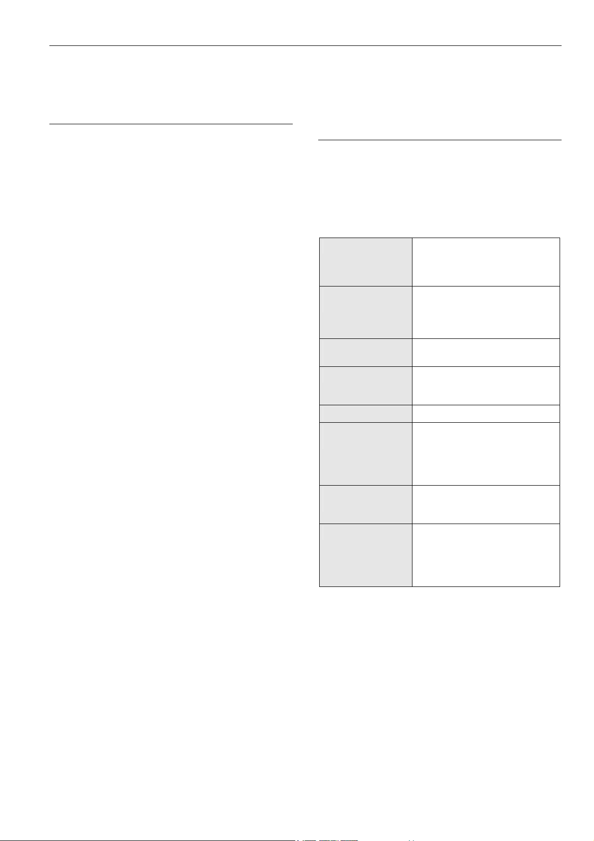
Pollution degree Pollution Degree 2,
suitable for use in residential
controls, commercial controls,
in a clean environment.
Overvoltage
category
Rated impulse
voltage
Automatic action Type 1.C
Software class
Ball-pressure test
temperature
Category II
for mains-powered (16A) controls
Category I
for 24 V powered controls
2500 VAC
(micro-interruption for the relay
outputs)
Class A
75 °C for all housing and plastic
parts
125 °C in the case of devices
applied with voltage-carrying parts
and connectors
Electromagnetic
interference
System transformer Europe: safety isolating
Table 1 System data as per EN60730-1
3 EN1Z-0921GE51 R0709
Tested at 230 VAC,
with the modules in normal
condition.
transformers according to
IEC61558-2-6
U.S.A. and Canada: NEC Class-2
transformers
System Overview LION System
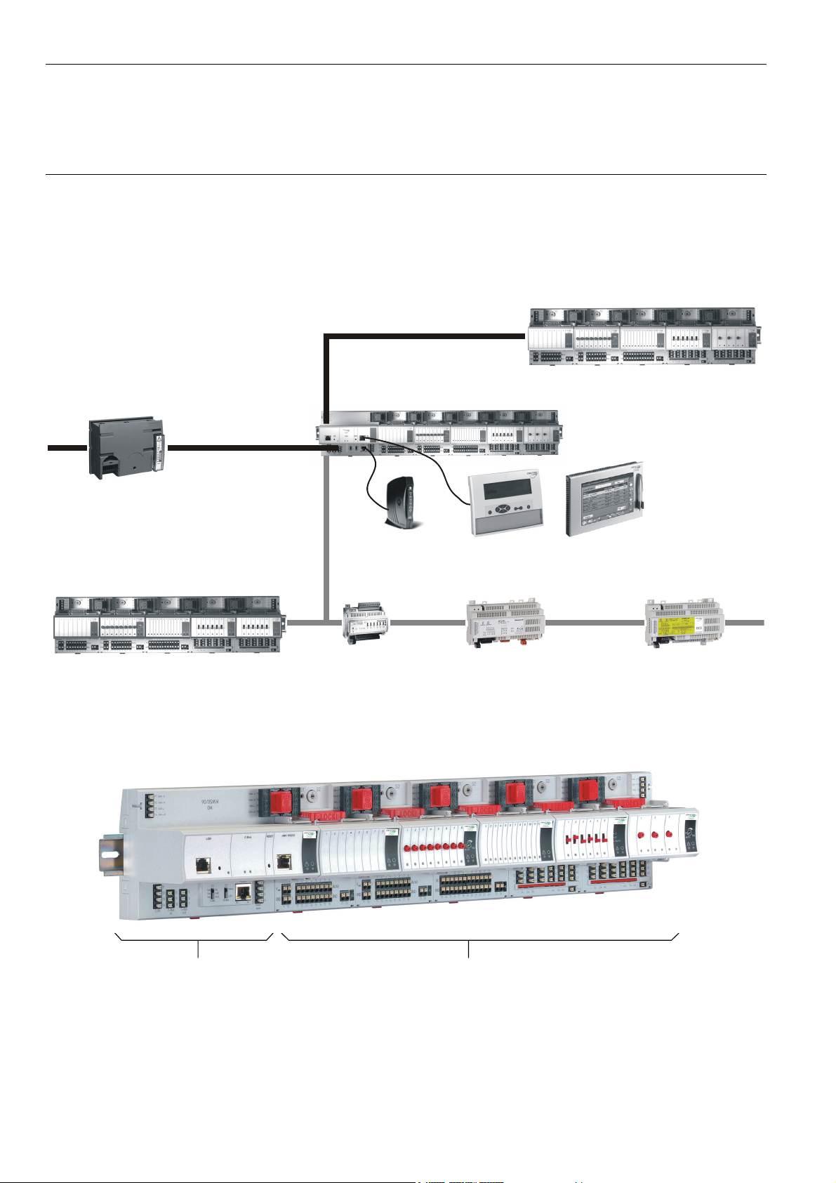
System Overview
System Architecture
An LION System consists of the CLLIONLC01 Controller and various I/O modules.
The CLLIONLC01 Controller provides interface connections, which allow connection to external systems.
Auxiliary parts enable special features.
Panel I/O (CLIOPxx)
Panel Bus (<40 m)
existing XL500
controllers
C-Bus
CLLIONLC01 + CLIOxx
LonWorks Bus
LonWorks I/O (CLIOLxx)
Fig. 1 LION System architecture
CLMMI00N22 or CLMMI00N31MODEM
XFCLxxxXFCxxx SERVAL
Controller I/O Modules
Fig. 2 CLLIONLC01 Controller and I/O modules
EN1Z-0921GE51 R0709 4
LION System System Overview
X
X
X
X
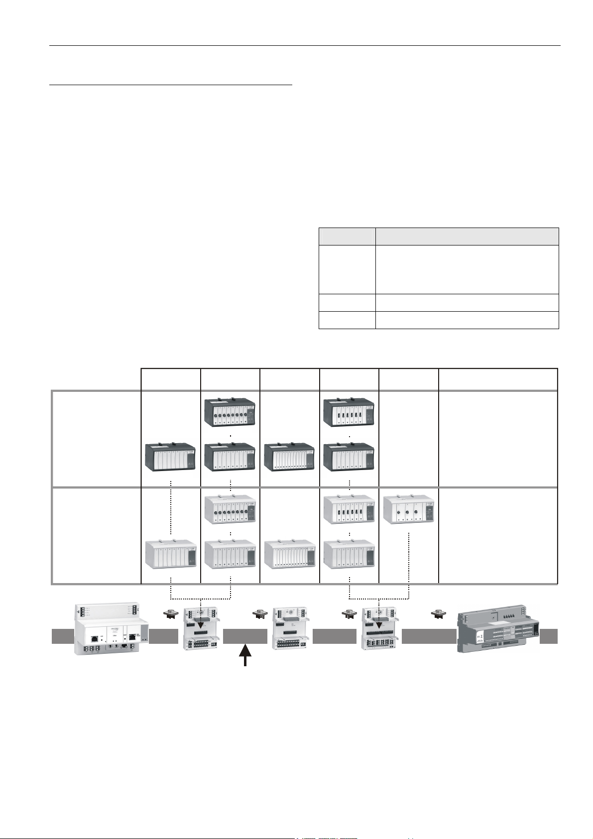
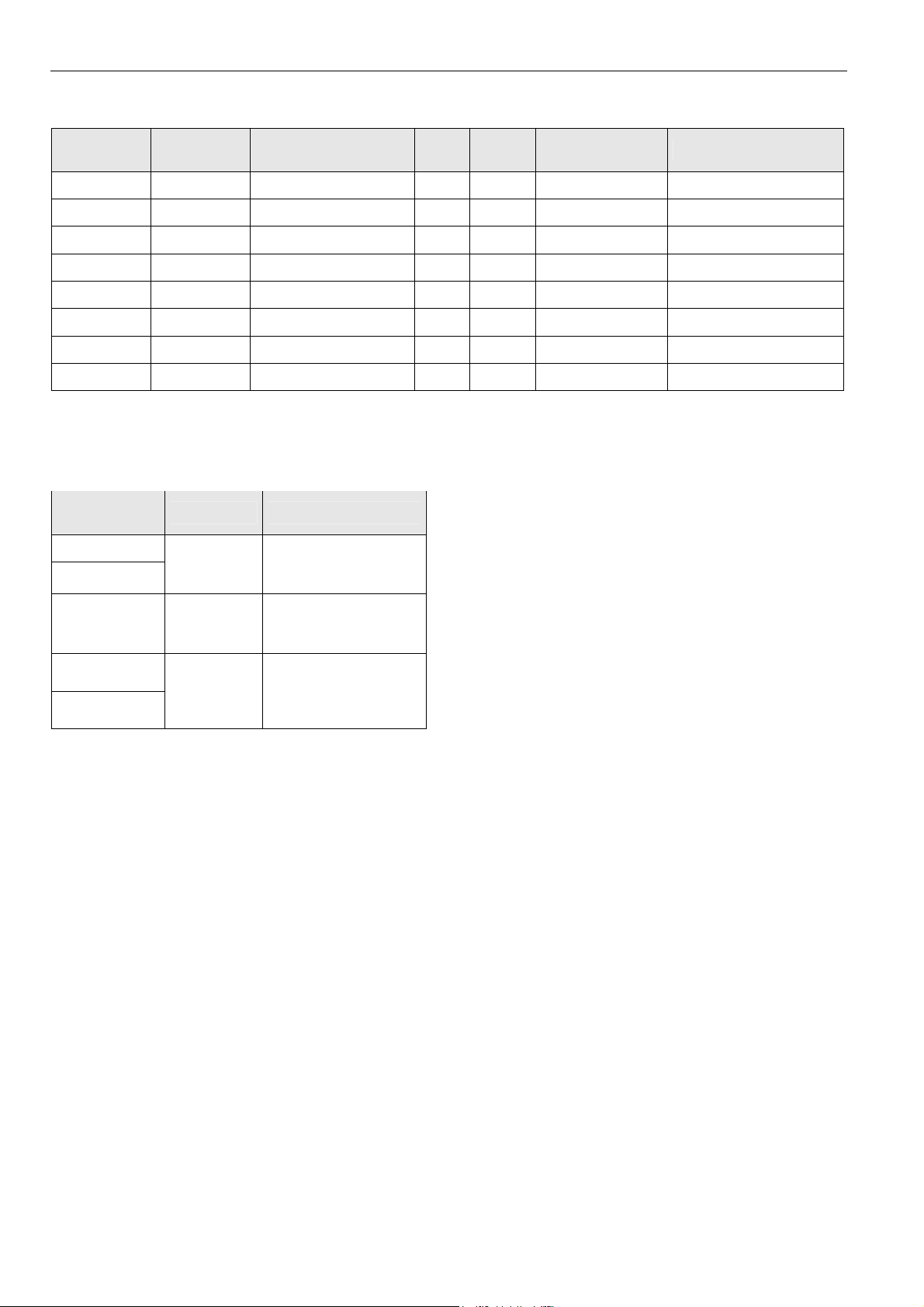
I/O Modules
Variants of Pluggable I/O Modules
There are 2 variants of pluggable I/O modules:
• Panel Bus I/O modules with communication via Panel
Bus (light gray housings)
Modules are automatically commissioned (with firmware
download) by the CLLIONLC01 Controller
• L
ONWORKS Bus I/O modules (dark gray housings) with
communication via L
compatible) for easy integration and use with 3
controllers
Mixed I/O Modules
Besides the pluggable Panel Bus I/O modules (consisting of
a terminal socket and a removable electronic module), there
are also mixed Panel Bus I/O modules. Specifically: the
CLIOP830A is a mixed Panel Bus I/O modules, featuring an
integrated terminal socket and a variety of inputs and
outputs.
Mixed Panel Bus I/O modules have a light-gray housing and
are likewise automatically commissioned (with firmware
download) by the CLLIONLC01 Controller.
ONWORKS (FTT10-A, link power
pluggable
ANALOG INPUT
pluggable
ANALOG OUTPUT
rd
-party
pluggable
BINARY INPUT
Terminal Sockets
Pluggable I/O modules are mounted on the appropriate
terminal sockets. Pluggable Panel Bus I/O modules and
pluggable L
ONWORKS Bus I/O modules use the same
terminal sockets. The terminal sockets are available with
push-in terminals (XS82…) or with screw-type terminals
(XSU82…).
Mixed I/O modules feature an integrated terminal socket.
Color Coding
To distinguish modules and components, the following color
coding is used:
Color Part
Red All of the user-accessible adjustable
mechanical parts (i.e., bridge connectors
and locking mechanism) and operating
controls (manual overrides, etc.)
Light-gray
Dark-gray
Panel Bus I/O modules
ONWORKS Bus I/O modules
L
Table 2 Color coding of LION Modules
pluggable
RELAY OUTPUT
pluggable
FLOATING
OUTPUT
MIXED I/Os
LonWorks
CLIOLR822A
BUS MODULES
CLIOL821A
PANEL
CLIOL822A
CLIOPR822A
CLIOL823A
BUS MODULES
CLIOP821A
CLLIONLC01
CLIOP822A
XS821-22
XSU821-22
CLIOP823A
LonWorks or Panel Bus
Fig. 3 Overview of I/O modules and terminal sockets
S823
SU823
CLIOLR824A
CLIOL824A
CLIOPR824A
CLIOP824A
CLIOPR825A
S824-25
SU824-25
CLIOP830A
PANEL BUS I/O MODULE
5 EN1Z-0921GE51 R0709
System Overview LION System
I/O Module Overview
Panel Bus
module
LONWORKS
Bus module
Description Inputs Outputs Manual controls LEDs 1)
CLIOP821A CLIOL821A Analog input module 8 – – –
CLIOP822A CLIOL822A Analog output module – 8 – 8 status LEDs
CLIOPR822A CLIOLR822A Analog output module – 8 8 Manual overrides 8 status LEDs
CLIOP823A CLIOL823A Binary input module 12 – – 12 status LEDs
CLIOP824A CLIOL824A Relay output module – 6 2) – 6 status LEDs
CLIOPR824A CLIOLR824A Relay output module – 6 2) 6 Manual overrides 6 status LEDs
CLIOPR825A – Floating output module – 3 3 Manual overrides 3 pairs of status LEDs
CLIOP830A -- Mixed I/O module 20 14 -- 18 status LEDs
1)
In addition to the power LED and service LED
2)
Changeover outputs
Table 3 Overview of I/O modules
Corresponding Terminal Sockets
I/O module
CLIOP/CLIOL…
…821
…822
…823
…824
…825
Socket Scope of delivery
XS821-22
XSU821-22
XS823
XSU823
1 terminal socket,
1 bridge connector
1 swivel label holder
1 terminal socket,
1 bridge connector
1 swivel label holder
1 terminal socket,
XS824-25
XSU824-25
1 bridge connector
1 swivel label holder
1 long cross connector
Table 4 Pluggable I/O modules and corresponding
terminal sockets
Note
In the following e.g., …822 is used to summarize all analog
output modules (Panel Bus/L
ONWORKS Bus, with/without
manual overrides)
EN1Z-0921GE51 R0709 6
LION System System Overview
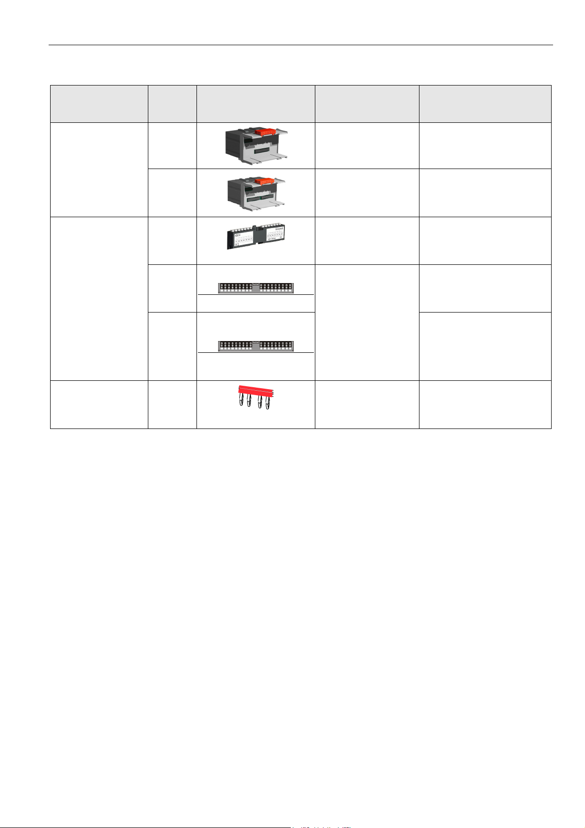
Auxiliary Parts
Corresponding
Module Type Figure
I/O modules
Information
CLIOP/CLIOL…
Manual disconnect
modules
Auxiliary terminal
package
Cross connectors,
short (yellow)
XS812
XS812RO
XS814
XS830
XS831
XS817
A1 A2A3A4
A1 B1 A2 B2
A5 A6A7A8 A9
A3 B3
B5 B6B7B8 B9
B1 B2B3B4
A5 B5 A6 B6
A4 B4 G1 G2
A8 B8
A7 B7
…821
…822
…823
…824
…825
Module allows disconnection of
individual I/O signals
Module allows disconnection of
individual I/O signals
For 24 V applications only
Two groups of 7 terminals
All pluggable LION I/O
modules
connected to each other for
redistributing voltage (see also
Fig. 94)
Two groups of nine internally-
connected push-in terminals, for
distributing signals/power (see
also Fig. 96).
CLIOP830A, only
Two groups of four pairs of
push-in terminals, for converting
0…20 mA signals into
0…10 Vdc signals, and one
push-in ground terminal per
group. (see also Fig. 98)
Connects 3 relay commons,
…824
…825
required in case of line voltage
and low voltage in the same I/O
module
Table 5 Auxiliary parts
Spare Parts
7 EN1Z-0921GE51 R0709
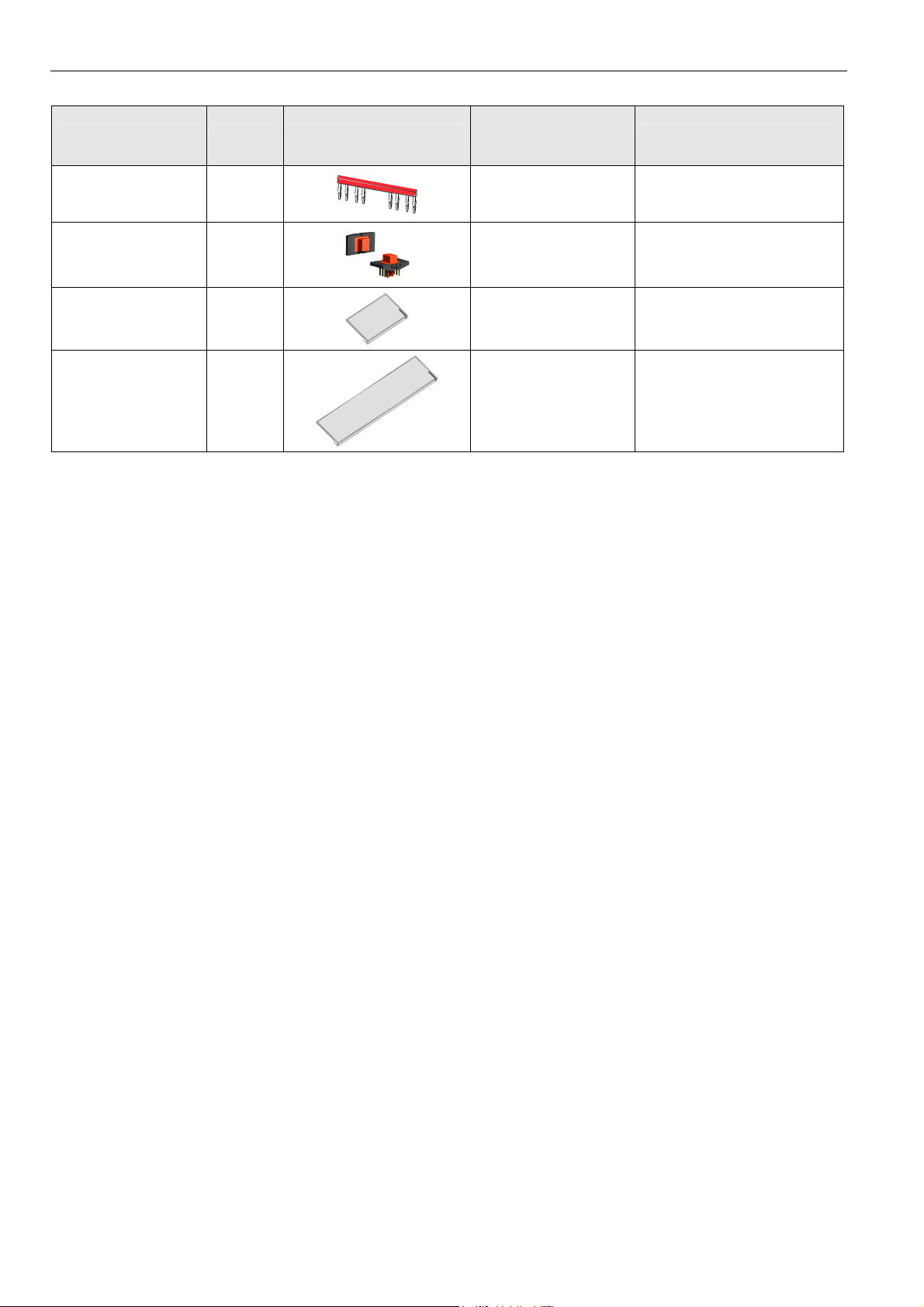
System Overview LION System
Corresponding
Module Type Figure
I/O modules
CLIOP/CLIOL…
Information
Cross connectors, long
(red)
Connector bridge XS816
Swivel label holder XAL10
Swivel label holder XAL11
Table 6 Spare parts
XS815
…824
…825
All LION I/O modules
All pluggable LION I/O
modules
CLIOP830A, only
Connects 6 relay commons
Connects CLLIONLC01 and I/O
modules
Can be plugged into socket, for
attaching label generated by
the engineering tool
Can be plugged into module,
for attaching label generated by
the engineering tool.
EN1Z-0921GE51 R0709 8
LION System System Overview
Interfaces and Bus Connections
The LION System can be connected to the following devices
and systems:
Panel Bus
• For communication with up to 16 Panel Bus I/O modules
• Polarity-insensitive
L
ONWORKS Bus
• For communication with other LONWORKS Bus devices
within the building
• FTT10, link power compatible
• Polarity-insensitive
C-Bus
• For communication with other controllers, e.g., existing
Excel 500 Controllers
HMI
• For connecting an operator interface (e.g., CLMMI00N22
or CLMMI00N31) or a laptop, e.g., for engineering
Modem
• For connecting a modem or an ISDN terminal adapter
Technical Data
System Data
Operating voltage 24 VAC, ± 20 %, 21 … 30 VDC
Max. number of C-Bus
participants
Power consumption
30
Max. 3.57 A
(1 CLLIONLC01 Controller
+ 16 I/O modules)
Standards
Protection class IP20
Product standard EMC EN 60730-2-9
Testing electrical
components
Certification CE
System transformer
Low-Voltage Device
Safety Assessment
Table 8 Standards
IEC68
The system transformer(s) must
be safety isolating transformers
according to IEC 61558-2-6.
In the U.S.A. and Canada, NEC
Class 2 transformers must be
used.
EN 60730-1
EN 60730-2-9
Operational Environment
Ambient operating
temperature
Ambient operating
humidity
Ambient storage
temperature
Ambient storage
humidity
Vibration under
operation
Dust, vibration According to EN60730-1
RFI, EMI Home environment
Table 9 Operational environment
0 … 50 °C (32 … 122 °F)
5 … 93 % rel. humidity
(non condensing)
–20 … 70 °C (–4 … +158 °F)
5 … 95 % rel. humidity
(non condensing)
0.024” double amplitude
(2 … 30 Hz),
0.6 g (30 … 300 Hz)
Push-in terminals 1.5 mm2
Screw-type terminals 1.5 mm2
Overvoltage protection
Calculated lifetime of
weakest component
under typical operating
conditions
Table 7 System data
9 EN1Z-0921GE51 R0709
All inputs and outputs are
protected against 24 VAC and
40 VDC overvoltage as well as
against short-circuiting.
MTBF
≥ 13.7 years
Planning LION System
Planning
Overview
Engineering with CARE
During CARE engineering, the type of I/O modules, terminal
assignment and module configuration are defined
depending on the application. The same applies to
engineering with COACH (which is possible starting with
COACH version 2.02).
Planning
In this step, the following has to be defined, if applicable:
• Power supply
• Fusing
• Earth grounding
• Lightning protection
• Panel Bus wiring
• Design of a L
• Design of a C-Bus network
• Useful accessories
• Cable selection
ONWORKS network
Transformer Selection
Note
In Europe the system transformer(s) must be safety isolating
transformers according to IEC61558-2-6.
In the U.S.A. and Canada, NEC Class-2 transformers must
be used.
Power Consumption
When selecting the appropriate transformer, take into
account the number of individual modules, accessories, and
field devices in determining the total power consumption.
Devices powered
CLLIONLC01 with
CLMMI00N22 (backlight ON)
and with watchdog load (max.
500 mA)
CLLIONLC01 with
CLMMI00N22 (backlight ON)
but without watchdog load
Power consumption
24 VAC 24 VDC
690 mA 640 mA
190 mA 140 mA
…821 130 mA 80mA
…822 160 mA 90 mA
…823 180 mA 130 mA
…824 140 mA 90 mA
…825 140 mA 90 mA
CLIOP830A 200 mA 95 mA
Table 10 Power consumption of LION System components
depending on power supply
Connectable Power Supplies
CentraLine CRT Series (Europe)
Transformer Primary side Secondary side
CRT 2 220/230 VAC 24 VAC, 50 VA, 2 A
CRT 6 220/230 VAC 24 VAC, 150 VA, 6 A
CRT 12 220/230 VAC 24 VAC, 300 VA, 12 A
Table 11 CentraLine CRT series transformers data
EN1Z-0921GE51 R0709
10
LION System Planning
CentraLine 1450 Series (North America)
• 50/60 Hz
• Insulated accessory outputs
• Built-in fuses
• Line transient /surge protection
• AC convenience outlet
• NEC Class-2
Part number
1450 7287
-001 120 VAC 24 VAC, 50 VA
-002 120 VAC
-003 120 VAC
-004 240/220 VAC 24 VAC, 50 VA
-005 240/220 VAC
-006 240/220 VAC
Table 12 CentraLine 1450 series transformers data
Standard Transformers (Europe, North America)
Standard commercially available transformers used to
supply power to LION Systems must fulfill the following
specifications:
Output voltage Impedance AC current
Primary side Secondary side
2 x 24 VAC, 40 VA,
and 100 VA from separate
transformer
24 VAC, 100 VA,
and 24 VDC; 600 mA
2 x 24 VAC, 40 VA,
and 100 VA from separate
transformer
24 VAC, 100 VA, and
24 VDC, 600 mA
Power Supply of Field Devices
Depending upon the power consumption of the field devices
used, it is possible to use either a single transformer to
power both the CLLIONLC01 and attached field devices, or
it may be necessary to employ an additional transformer.
See also section "Field Device Cables" on page 14 and
connection examples on page 30.
Fusing Specifications
For connection examples see description of the I/O modules
on page 40 and following.
F1 (Fusing for CLLIONLC01 and I/O Modules))
Rating: 4 A, time-lag fuse (slo-blo)
For example:
Manufacturer: Littlefuse
Type: 218004
F2 (Fusing for Active Field Devices)
Depends upon loads in use.
System Protective Earth Grounding
LION Systems comply with SELV (Safety Extra-Low
Voltage). Earth grounding is therefore not recommended.
However, if compliance with EN60204-1 is required, see
Appendix 1.
Lightning Protection
24.5 VAC to 25.5 VAC
24.5 VAC to 25.5 VAC
24.5 VAC to 25.5 VAC
Table 13 Requirements for standard transformers
RIN-APU24 Uninterruptable Power Supply
The RIN-APU24 Uninterruptable Power Supply can be wired
to power LION Systems.
See also RIN-APU24 Uninterruptable Power Supply –
Mounting Instructions (MU1B-0258GE51) for detailed wiring
diagrams.
11 EN1Z-0921GE51 R0709
≤ 1.15 Ω
≤ 0.40 Ω
≤ 0.17 Ω
max. 2 A
max. 6 A
max. 12 A
Please contact your local CentraLine representative for
information on lightning protection.
Panel Bus Topologies
• Up to 16 Panel Bus I/O modules can be controlled by a
single CLLIONLC01.
• Panel Bus I/O modules must be addressed using the
HEX switch on the terminal socket.
• Maximum distance between controller and Panel Bus
I/O module: 40 m.
• No bus termination
• Polarity-insensitive
Planning LION System
X
LONWORKS Bus Topologies
The LONWORKS Bus is a 78-kilobit serial link that uses
transformer isolation so that the bus wiring does not have a
polarity. I.e. it is not important which of the two LONWORKS
Bus terminals are connected to each wire of the twisted pair.
The L
ONWORKS Bus does not need to be shielded on the
controller module side.
The LONWORKS Bus can be wired in daisy chain, star, loop
or any combination thereof as long as the maximum wire
length requirements are met.
Configuration
The recommended configuration is a daisy chain with two
bus terminations. This layout allows for max. L
ONWORKS
Bus lengths, and its simple structure presents the least
number of possible problems, particularly when adding on to
an existing bus.
See also “L
ONWORKS Mechanisms”, Product Literature no.:
EN0B-0270GE51.
C-Bus Topologies
Accessories
Besides the auxiliary parts of Table 5 on page 7, the
following accessories are available.
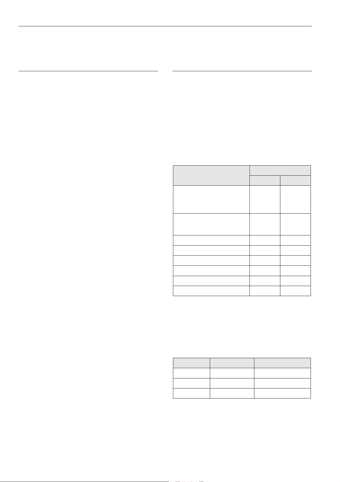
Preconfigured Connection Cables
Type
XW882
XW582
+ XW586
XW884
XW885 Laptops
XW585
+ XW586
XW586 Modems
Connecting
CLLIONLC01 with
CLMMI00N22 Operator
Interface
CLMMI00N22 Operator
Interface
Adapter cable for Excel
500/600 Controllers
Laptops
Features
5 m, shielded,
RJ45 plug with clip
See XW582 and
XW586
0.2 m, shielded,
RJ45 – 9 pin sub-D
3 m, shielded,
RJ45 plug with clip
See XW582 and
XW586
1.8 m, RJ45 – 9 pin
sub-D
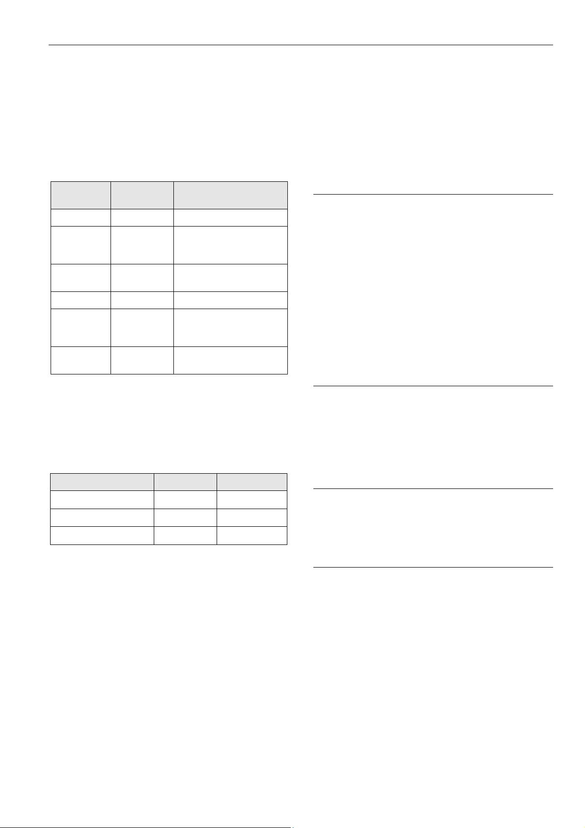
Via the C-Bus up to 30 C-Bus devices (e.g., controllers, etc.)
can communicate with one another and a PC central. The
C-Bus must be connected via the individual controllers
(open ring).
Note
Star connection is not allowed because uncontrollable line
reflections may occur.
Instead of LION Controllers, other C-Bus controllers (e.g.,
the Excel 500, Excel 100, PANTHER) can also be
connected.
LION
Excel 100 Excel 500
PANTHER
Fig. 4 C-Bus topology Excel 5000
Table 14 Preconfigured connection cables
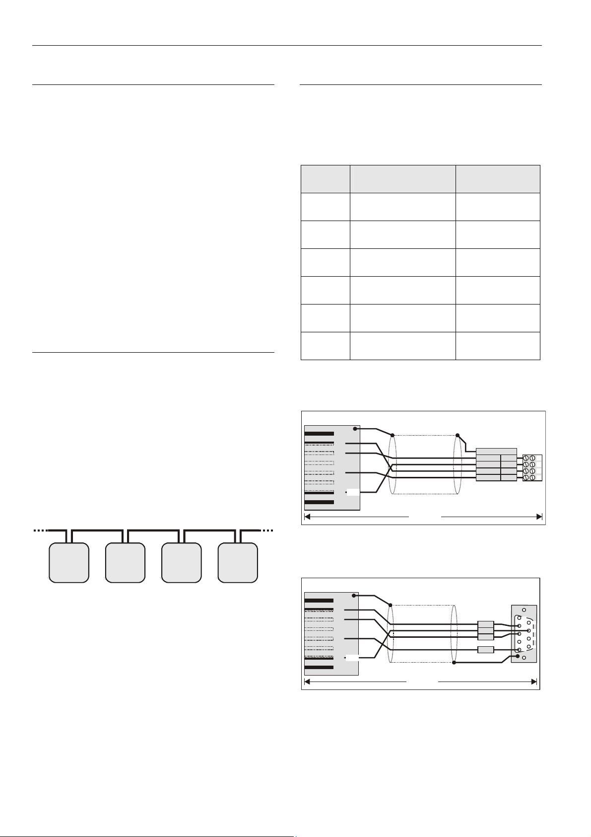
XW882 Cable Details
RJ45 plug with clip at front
12
SHIELD
3678
4
5
+5V
XW882
Fig. 5 CLLIONLC01/CLMMI00N22 cable details
XW884 Cable Details
RJ45 plug with clip at front
12
SHIELD
3678
4
5
+5V
LOOSE
ENDS
R
G
L
E
Y
R
B
G
R
W
H
sub-D female
R
x
R
T
T
x
G
N
CLMMI00N22
WIRING
TERMINALS
A
Y
n
(
d
e
)
s
u
t
o
W
O
L
T
D
x
W
O
E
V
+
5
N
R
N
E
E
D
x
N
E
T
G
I
D
RS232 plug
D
S
D
D
1
2
3
4
1
6
2
7
3
8
4
9
5
W884
Fig. 6 CLLIONLC01/Excel 500/600 cable details
EN1Z-0921GE51 R0709
12
LION System Planning
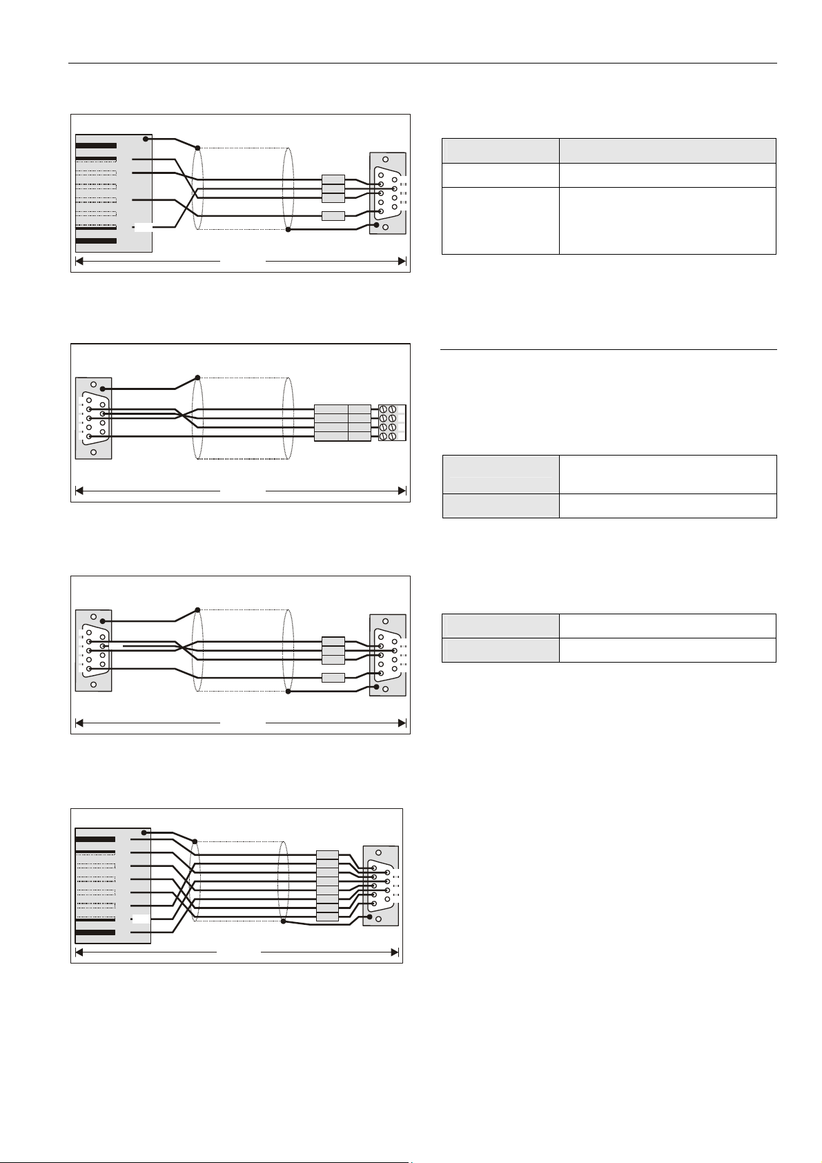
XW885 Cable Details
RJ45 plug with clip at front
12
SHIELD
3678
4
5
+5V
XW885
Fig. 7 CLLIONLC01/laptop cable details
XW582 Cable Details
LOOSE
to XC5010C
1
6
2
7
3
8
4
9
5
SHIELD
ENDS
XW582
Fig. 8 XW582 cable details
XW585 Cable Details
RS232 plug
sub-D female
1
6
2
7
+5V
3
8
4
9
5
SHIELD
RS232 plug
sub-D female
D
x
R
R
S
T
T
D
x
D
N
G
CLMMI00N22
WIRING
TERMINALS
W
O
L
L
E
T
Y
B
G
W
D
x
W
O
R
E
V
+
5
N
R
N
E
E
D
R
x
N
E
T
G
I
D
H
RS232 plug
sub-D female
R
D
x
R
S
T
T
D
x
D
N
G
LONWORKS Bus Termination Modules
Type Description
1
209541 LONWORKS Bus termination module
6
2
7
3
8
4
5
9
XAL-Term
L
ONWORKS connection and
termination module, which can be
mounted on DIN rails and in fuse
boxes
Table 15 LONWORKS Bus termination modules
Cable Specifications
Power Supply Cables
When checking the length of the power supply cable, the
1
2
3
4
1
2
3
4
5
connection cables to all I/O modules must be taken into
account.
Max. length 3 m (per side of the controller),
see Fig. 33 on page 26
Cross section
min. 0.75 mm
2
(AWG 18)
Table 16 Power supply cables specification
Panel Bus Cables
Max. length
6
7
Cable type
8
9
Table 17 Panel Bus cables specification
40 m
twisted pair, e.g., J-Y-Y 2 x 2 x 0.8
XW585
Fig. 9 XW585 cable details
XW586 Cable Details
RJ45 plug with clip at front
12
SHIELD
3678
4
5
+5V
XW586
RS232 plug
sub-D male
D
C
D
R
S
D
D
x
R
S
R
T
T
D
x
S
T
C
D
T
R
G
D
N
1
6
2
7
3
8
4
9
5
Fig. 10 XW586 cable details
13 EN1Z-0921GE51 R0709

Planning LION System
LONWORKS Bus Cables
Cable type Max. bus length
Belden 85102 (plenum) 2700 m (8900 ft)
Belden 8471 (non-plenum) 2700 m (8900 ft)
Level IV, 22 AWG 1400 m (4600 ft)
JY (St) Y 2 x 2 x 0.8 900 m (3000 ft)
TIA568A Cat. 5 24AWG, twisted pair 900 m (3000 ft)
Table 18 Doubly-terminated bus specifications
Notes
• The cable types listed above are as recommended by
Echelon in their FTT-10A User Guide.
• The cable recommended by CentraLine is the level IV,
22 AWG, solid core, non-shielded cable.
• Belden part numbers are 9H2201504 (plenum) and
9D220150 (non-plenum).
FTT Specification
The FTT specification includes two components that must
be met for proper system operation:
• The distance from each transceiver to all other
transceivers and to the termination must not exceed the
max. node-to-node distance.
• If multiple paths exist, the maximum total wire length is
the total amount of wire used.
Cable type
Max. node-tonode distance
Max. total wire
length
Note
In the event that the limit on the total wire length is
exceeded, the FTT physical layer repeaters (FTT 10A) can
be added to interconnect segments. This increases the
overall length by an amount equal to the original
specification for that cable type and bus type for each
repeater used.
For example, adding repeaters for a doubly-terminated bus
using JY (St) Y 2 x 2 x 0.8 cable increases the maximum
length 900 m (3000 ft) for each repeater.
Field Device Cables
Cross-sectional area
Type of signal
24 VAC power
0…10 V signals 0.081 – 2.08 mm2 (28 – 14 AWG)
Table 20 Cable sizing for connection of field devices
For wiring field devices see page 30.
≤ 100 m (300 ft)
(Fig. 40 on p. 30)
one transformer
1.5 mm2
(16 AWG)
≤ 400 m (1300 ft)
(Fig. 41 on p. 30)
separate
transformers
not allowed for
> 100 m (300 ft)
Belden 85102 500 m (1650 ft) 500 m (1650 ft)
Belden 8471 400 m (1300 ft) 500 m (1650 ft)
Level IV, 22AWG 400 m (1300 ft) 500 m (1650 ft)
JY (St) Y 2 x 2 x 0.8 320 m (1050 ft) 500 m (1650 ft)
TIA568A Cat. 5
24AWG, twisted pair
Table 19 Free topology (singly-terminated) specifications
250 m (825 ft) 450 m (1500 ft)
NOTICE
Unpredictable reflections on the bus due to step change
in line impedance characteristics!
► Do not use different wire types or gauges on the same
ONWORKS network segment.
L
EN1Z-0921GE51 R0709
14

LION System Planning
C-Bus Cables
Note
Observe national regulations for C-Bus cables!
• For Europe only shielded cable is permitted.
• For the U.S. shielded or unshielded cable can be used.
Cable type Description Recommended for
J-Y-(ST)Y
2 x 2 x 0.8
A-Y-(ST)Y
2 x 2 x 0.8
AK 3702
AK 3740A shielded
Belden 9842 twisted pair Europe, US also possible
Belden 9841 shielded US
AK 3702
AK 3740A shielded
Table 21 C-Bus cable types
Maximum Cable Length
The maximum C-Bus cable length is 1200 m (4000 ft).
See section "C-Bus Topologies" on page 12.
shielded,
twisted pair
shielded,
twisted pair
unshielded,
twisted pair
unshielded,
twisted pair
Europe, inside cabinet
Europe, outside cabinet
US
not approved for Europe
US (low-cost)
not approved for Europe
US
not approved for Europe
US (low-cost)
not approved for Europe
15 EN1Z-0921GE51 R0709
Planning LION System
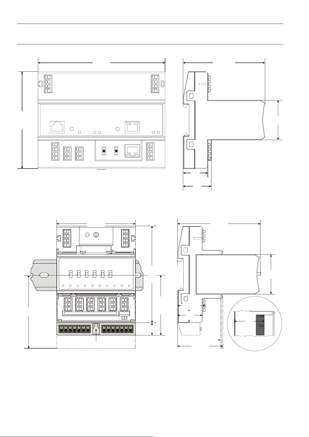
Dimensions
Controller Module
144
110
Fig. 11 Controller module, outside dimensions (in mm)
28
32
92.75
45
Pluggable I/O Modules
89.5 94.1
LOCK
45
83
110
67.5
30.6
28
SCREW-TYPE
TERMINALS
38
14
XS814 Aux. Terminal Package (optional)
SWIVEL LABEL HOLDER
51.5
Fig. 12 Pluggable I/O modules (shown with manual overrides), including XS814 Aux. Terminal Package, dimensions (in mm)
EN1Z-0921GE51 R0709
16
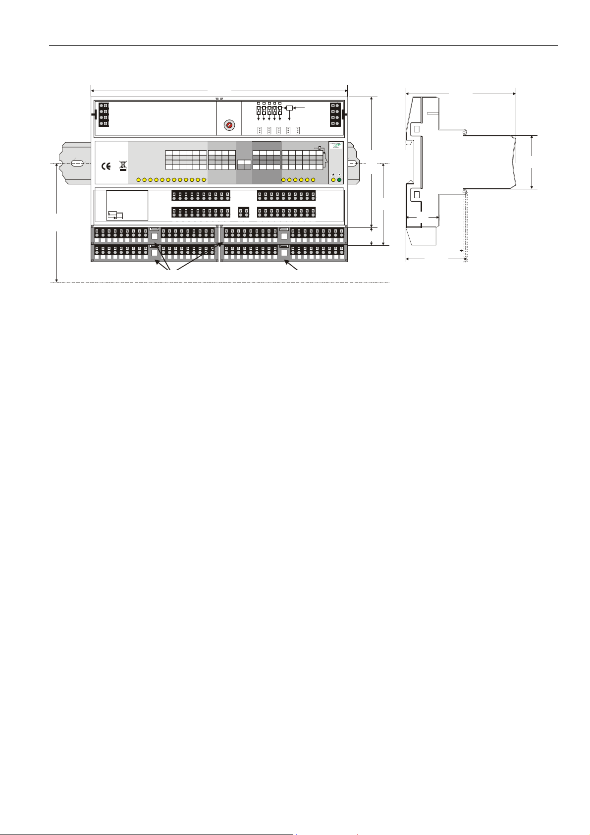
LION System Planning
Mixed I/O Module
216
75
71
COM a
COM b
72
24V~
100
73
24V~0
74
1 12 23 34 45 56 67
Install. Instr.
DI
EN1B-0375GE51
CLIOP830A
12 BI / 8 AI / 8 AO / 6 RO
24V, 15VA, T50
0706AX0001-XFU830A
8
Made in Germany
0532
A5 A6 A7 A8 A9
A1 A2A3A4
CLEARANCE
A1 A2 A3 A4 A5 A6 A7 A8 A9 B1 B2 B3 B4 B5 B6 B7 B8 B9
A
C
Binary Inputs
B8 B9 B10
B7
B11B12
7
8 9 10
11 12
1 2 3 4 5 6
B5 B6
B1 B2B3B4
8 9310411512
7 8 9
10 11 12 17 18 19 20
1 21 222324
2
B5 B6 B7 B8 B9
B1 B2B3B4
4
5
3
6
2
7
24V for relay 1...5
1
8
0
9
S2
F
A
E
B
C
D
J1 J2 J3 J4 J5
Analog Inputs Analog Outputs 24V Relays
AI6
AI7
18 19 20
AI3
GND
AI8
AO5
AO6 AO7 AO8
25
262728 35
G1 G2
21 22 23 24
AI4 41
42
AO1 AO2 AO 3 AO4 NO1 NO2 NO3 NO4 NO5 NO6
AI5
17
13 14 15 16
AI1 AI2
25 26 27 28 35 36 37 38 39 40
6 131415 16
41 42
A5 A6 A7 A8 A9
A1 A2A3A4
A1 B1 A2 B2 A3 B3 A4 B4 G1 G2A5 B5 A6 B6 A7 B7 A8 B8
D = XS831 Aux. Terminal Package (optional)A, B, and C = XS830 Aux. Terminal Packages (optional)
Fig. 13 Mixed I/O Module CLIOP830A (shown with four auxiliary terminal packages), dimensions (in mm)
External
COM a
40
24V
COM b
IN3
IN1 IN2
IN4
36 37 38 39 40
29 30 31 32 33 34
29 30 31 32 33 34
B
B1 B2B3B4
D
24V~
24V~0
IN5 IN6
DO
B5 B6 B7 B8 B9
76
77
78
!
110
69
28
15
SWIVEL LABEL HOLDER
92.5
45
51.5
17 EN1Z-0921GE51 R0709
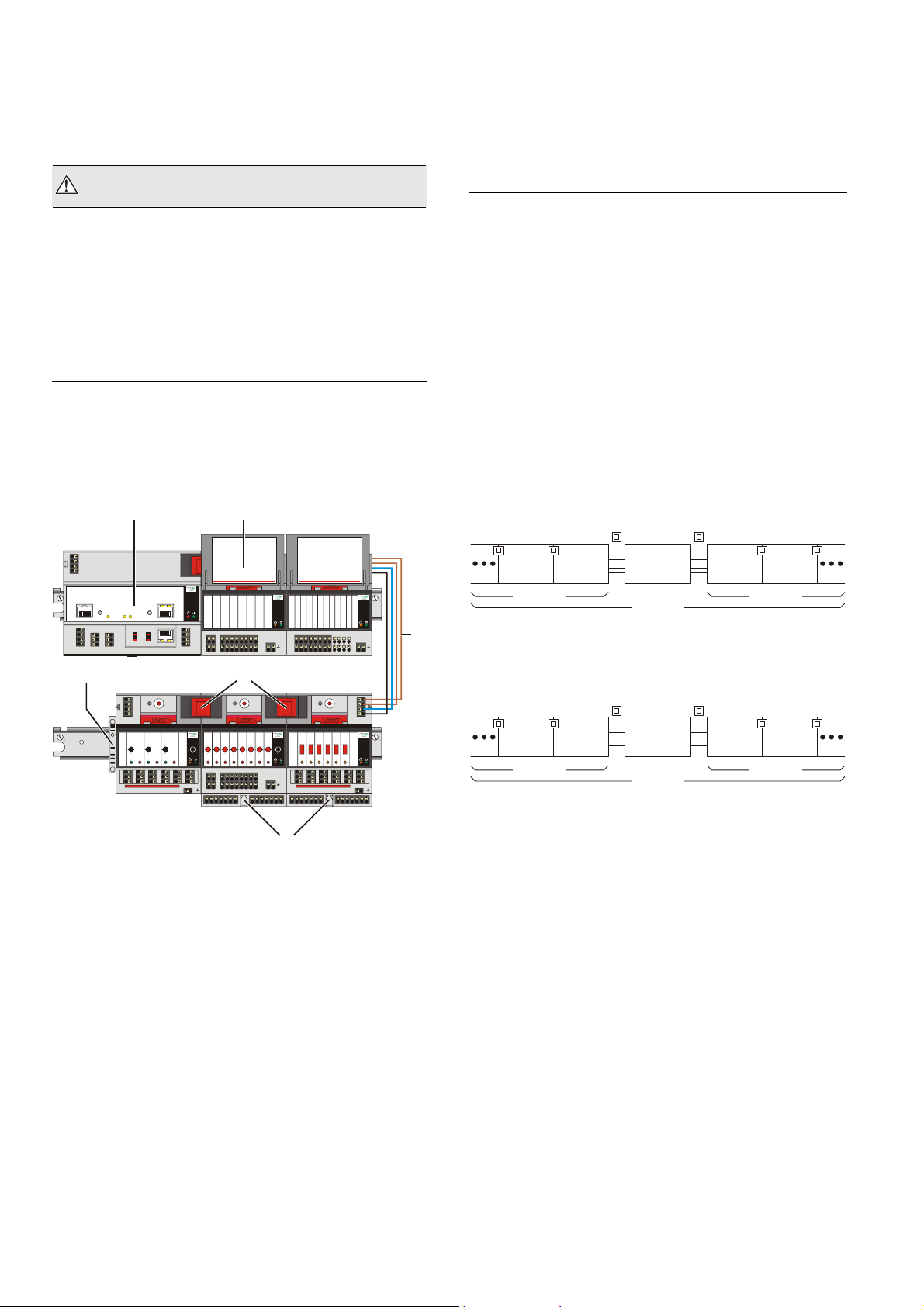
Mounting/Dismounting Modules LION System
A
Mounting/Dismounting Modules
WARNING
Risk of electric shock or equipment damage!
► Do not touch any live parts in the cabinet.
► Disconnect the power supply before you start to install
the LION System.
More than one disconnect switch may be required to deenergize the system.
► Do not reconnect the power supply until you have
completed the installation.
Note
The terminal socket of each pluggable I/O module can be
mounted and wired before inserting and locking the
corresponding electronic module.
1 2
1:ABCDFERTAQWESDERT1
2:ABCDFERTAQWESDERT2
3:ABCDFERTAQWESDERT3
4:ABCDFERTAQWESDERT4
5:ABCDFERTAQWESDERT5
71 COM a
72 COM b
73 24V
~
74 24V 0
~
C-BUS RESET
LON
8765 4 32 1 8765 4 32 1
11 1
S1 S2
9.6k all
12 285
76k
13 396
76k
14 410 7
C-Bus
C-Bus
C-Bus
LON
out
in
4
71 COM a
72 COM b
73 24V
74 24V 0
1
AAA
21
11
22
12
23
13
14 4424 5434 64 25
PRESS
COM a
6:ABCDFERTAQWESDERT6
COM b
7:ABCDFERTAQWESDERT7
8:ABCDFERTAQWESDERT8
24V
~
24V 0
~
PRESS
PC/HMI
!
Modem
Panel
8765 4 32 1
mid
LON
end
I/O Bus
Rx Tx
Power/
Alarm
5678
1234
21
22 12345678
AUX
GND GND
9
10 11 12 13 14 15 16 17 18 25 26
5
PRESS
S1 S2
5
4
3
6
2
7
1
8
0
9
F
A
E
B
D
C
~
~
3
2
31
41
51
32
42
52
33
43
53
PRESS
1234
0
100
AUTO
AAAAAAAA
!
21
22 12345678
616261
62
AUX
6363
GND GND
9
10 11 12 13 14 15 16 17 18 25 26
S1 S2
5
4
3
6
2
1
0
F
E
B
D
C
5678
7
8
9
A
Fig. 14 CLLIONLC01 and I/O modules mounted on
multiple DIN rails
!
AI/AOV
PRESS
0
UTO
!
AI/AOV
1:ABCDFERTAQWESDERT1
2:ABCDFERTAQWESDERT2
3:ABCDFERTAQWESDERT3
4:ABCDFERTAQWESDERT4
5:ABCDFERTAQWESDERT5
6:ABCDFERTAQWESDERT6
7:ABCDFERTAQWESDERT7
8:ABCDFERTAQWESDERT8
5 6 7 8 9 10
1 234
123456789101112
BI
GND
13 14 15 16 17 18 19 20 21 22 23 24 25 26
S1 S2
PRESS
1234
100
21
31
11
22
32
12
23
33
13
14 4424 5434 64 25
6
11 12
!
5
4
3
6
2
7
1
8
0
9
F
A
E
B
D
C
56
--1
--0
--AUTO
!
41
51
616261
42
52
62
43
53
6363
Mounting/Dismounting Controller/Sockets
Mounting Sockets
Notes
• When using both Panel Bus and LONWORKS Bus I/O
modules in a LION System, group both Panel Bus
modules (light gray) and LONWORKS Bus I/O modules
(dark gray), e.g., on different rails.
• Up to 10 Panel Bus I/O modules can be mounted to one
side of the controller. In total, up to 16 Panel Bus
I/O modules can be mounted to one controller.
• The CLLIONLC01 and the mixed Panel Bus I/O module
are mounted on the DIN rail in the same way as a
terminal socket.
PAN EL
BUS
3
Fig. 15 Max. number of Panel Bus I/O modules
I/O
max. 10
PANEL
BUS
I/O
CLLIONLC01
max. 16
LonWorks
BUS I/O
Fig. 16 Max. number of L
max. 10
LonWorks
BUS I/O
CLLIONLC01
max. 20
ONWORKS Bus I/O modules with
power supply via CLLIONLC01
PAN EL
BUS
I/O
LonWorks
BUS I/O
PAN EL
BUS
I/O
max. 10
LonWorks
LonWorks
BUS
BUS I/O
I/O
max. 10
Legend
1 CLLIONLC01
2 Swivel label holder
3 Cable connection
4 Stopper (from 3
rd
-party supplier)
5 Bridge connectors
6 Auxiliary terminal package
EN1Z-0921GE51 R0709
18
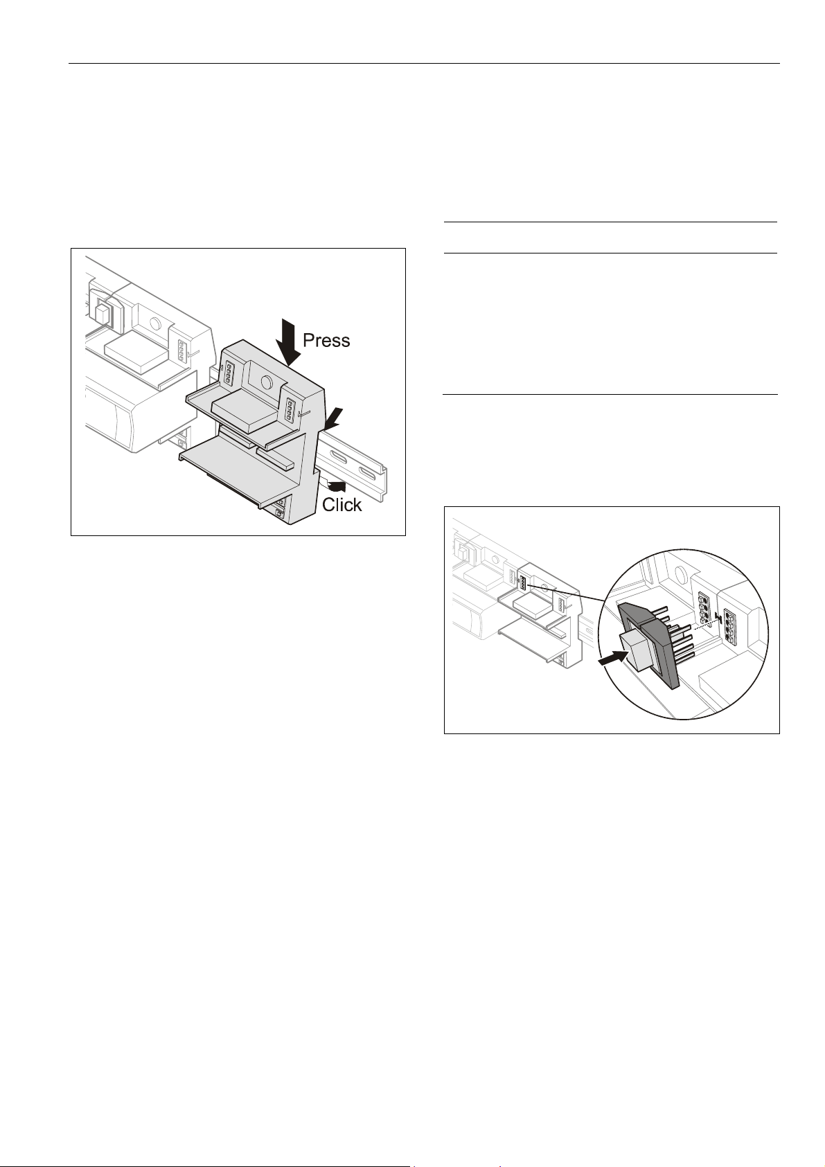
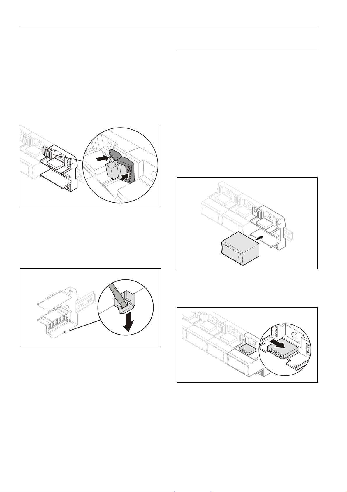
LION System Mounting/Dismounting Modules
► Angle the terminal socket at the upper edge of the DIN
rail until it snaps in.
► Swing the terminal socket down and apply gentle force
until it snaps into position with an audible "click".
► Position controller module and terminal sockets flush with
one another along the rail.
► If desired, mount stoppers at the ends of the rail to
prevent sliding.
Connecting Sockets
Controller, terminal sockets, and mixed I/O modules on the
same DIN rail can be connected mechanically and
electrically with bridge connectors.
Controller and terminal sockets on different DIN rails must
be connected using cables, see Fig. 14 and page 25.
NOTICE
Risk of malfunction!
► Wire Panel Bus I/O modules and LONWORKS Bus
I/O modules separately.
► When using both Panel Bus and LONWORKS Bus
I/O modules in a LION System, L
I/O modules must be connected to the controller via
LON terminals 11 … 14.
Position the bridge connector on terminals 71 … 74 of the
right hand terminal socket or mixed I/O module or controller
and on terminals 75 … 78 of the left hand terminal socket or
mixed I/O module or controller. Then press the bridge
connector down.
ONWORKS Bus
Fig. 17 Mounting terminal sockets
Note
Take care to not bend the Omega clamp, which serves to
establish the electrical contact with the DIN rail and which
located on the back of the terminal socket.
Fig. 18 Connecting terminal sockets with bridge
connector
Notes
• Bridge connectors transmit both communication signals
and power supply between modules.
• Removing bridge connectors will interrupt the trans-
mission of both communication signals and power supply
between the modules.
19 EN1Z-0921GE51 R0709
Mounting/Dismounting Modules LION System
Dismounting Sockets
Disconnecting Sockets
Release all bridge connectors before removing the controller
module and/or the terminal sockets and/or mixed I/O
modules from the DIN rail.
► Press down at the same time both the gray side wings
next to the red button and then pull the bridge connector
out of the module.
Fig. 19 Releasing bridge connectors
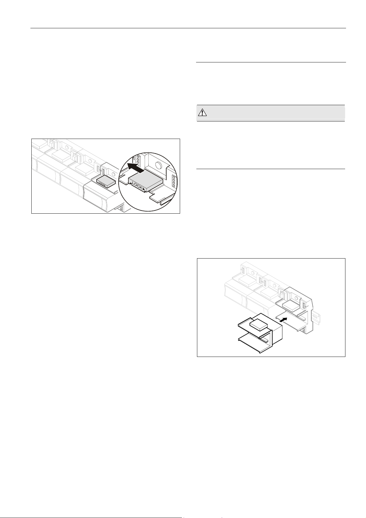
Mounting/Dismounting Electronic Modules
Mounting Electronic Modules
Note
Electronic modules can be removed from the socket or
inserted into the sockets without switching off the power
supply. The behavior of connected field devices must be
taken into consideration.
► Make sure that terminal socket und electronic I/O module
match; see Table 4 on page 6.
► Make sure that the red locking mechanism is in the open,
i.e., left, position.
► Gently push the electronic module onto the terminal
socket until snug.
Dismounting Controller / Terminal Sockets / Mixed I/O
Modules
► Insert a screwdriver into the latch on the underside of the
module and lever the red latch 2–3 mm downwards. The
module can then be swung away from the rail.
Fig. 20 Releasing latch
Fig. 21 Inserting the electronic module
► Lock the red locking mechanism by sliding it to the right.
Fig. 22 Locking the electronic module
Note
The red locking mechanism will not close if the electronic
module is not properly mounted.
EN1Z-0921GE51 R0709
20
LION System Mounting/Dismounting Modules
Dismounting Electronic Modules
Note
Electronic modules can be removed from the socket or
inserted into the sockets without switching off the power
supply. The behavior of connected field devices must be
taken into consideration.
► Open the red locking mechanism by sliding it to the left
and then gently pull the electronic module out of the
terminal socket.
Fig. 23 Dismounting the electronic module
Mounting/Dismounting Manual Disconnect
Modules
XS812 and XS812RO Manual Disconnect Modules are
mounted on the terminal socket appropriate for the
electronic module, see Table 4 on page 6. The electronic
module is mounted onto the manual disconnect module.
WARNING
Risk of electric shock or equipment damage!
The XS812RO Manual Disconnect Module is designed
for 24 V applications only!
► Never use the XS812RO Manual Disconnect Module with
line voltage.
Mounting Manual Disconnect Modules
► Make sure that manual disconnect module, electronic
module and terminal socket match, see Table 4 on
page 6.
► Make sure that the red locking mechanism is in the open,
i.e., left, position.
► Gently push the manual disconnect module onto the
terminal socket until snug.
► Lock the red locking mechanism by sliding it to the right.
Fig. 24 Mounting the manual disconnect modules
21 EN1Z-0921GE51 R0709
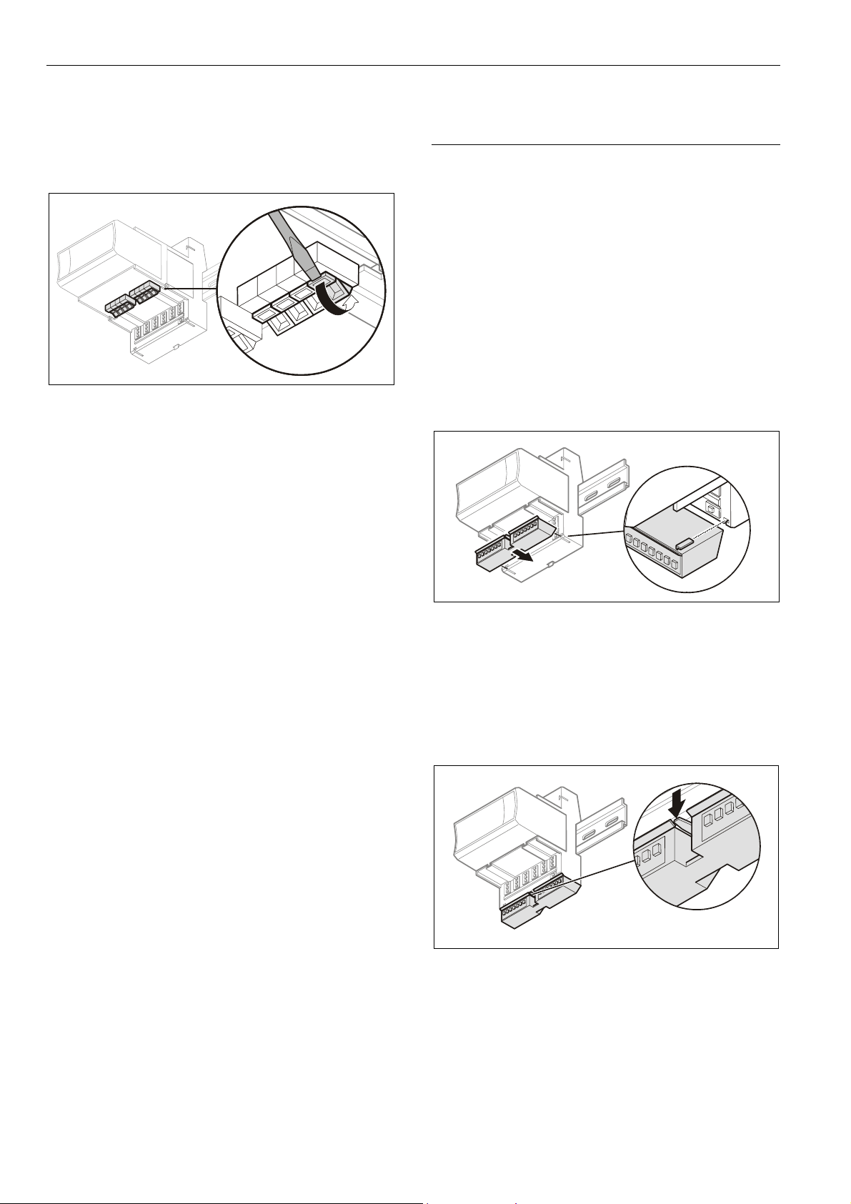
Mounting/Dismounting Modules LION System
Operating the Individual Switches
► Use a screwdriver to open/close the appropriate
disconnector switches of the manual disconnect
modules.
Fig. 25 Operating the disconnector switches
Dismounting Manual Disconnect Modules
► Open the red lock mechanism by sliding it to the left and
then gently pull the electronic module out of the terminal
socket.
Mounting/Dismounting Auxiliary Terminal
Packages
The XS814 Auxiliary Terminal Package can be mounted on
any pluggable I/O module.
The XS830 and XS831 Auxiliary Terminal Packages are
suitable for mixed I/O modules, only. Specifically, they can
be mounted on the top and/or bottom of the CLIOP830A.
For reasons of mechanical stability, a maximum of two rows
of Auxiliary Terminal Packages may be mounted together
on any given I/O module.
Mounting Auxiliary Terminal Packages
► Push the auxiliary terminal package onto the grooves of
the corresponding terminal socket / the mixed I/O
module.
Fig. 26 Mounting the auxiliary terminal package onto the
terminal socket / mixed I/O module
Dismounting Auxiliary Terminal Packages
► Push down the catch of the auxiliary terminal package
and pull it out of the grooves of the terminal socket / the
mixed I/O module.
Fig. 27 Dismounting the auxiliary terminal package from
the terminal socket / the mixed I/O module
EN1Z-0921GE51 R0709
22
LION System Mounting/Dismounting Modules
Mounting/Dismounting Cross Connectors
Note
The long cross connector (incl. in the scope of the delivery)
can be mounted to the XS824-25 or XSU824-25, as
required (Fig. 29). It can be dismounted (see Fig. 28) and, if
desired, replaced with one or two short connectors (optional
accessory, see Table 5 on page 7). It is not permitted to
replace these cross connectors with wire.
► Insert a screwdriver on one end of the cross connector
and swivel it to the right and to the left.
► Insert a screwdriver on the other end of the cross
connecter and swivel it to the right and to left until the
cross connector is released.
► If desired, insert another cross connector.
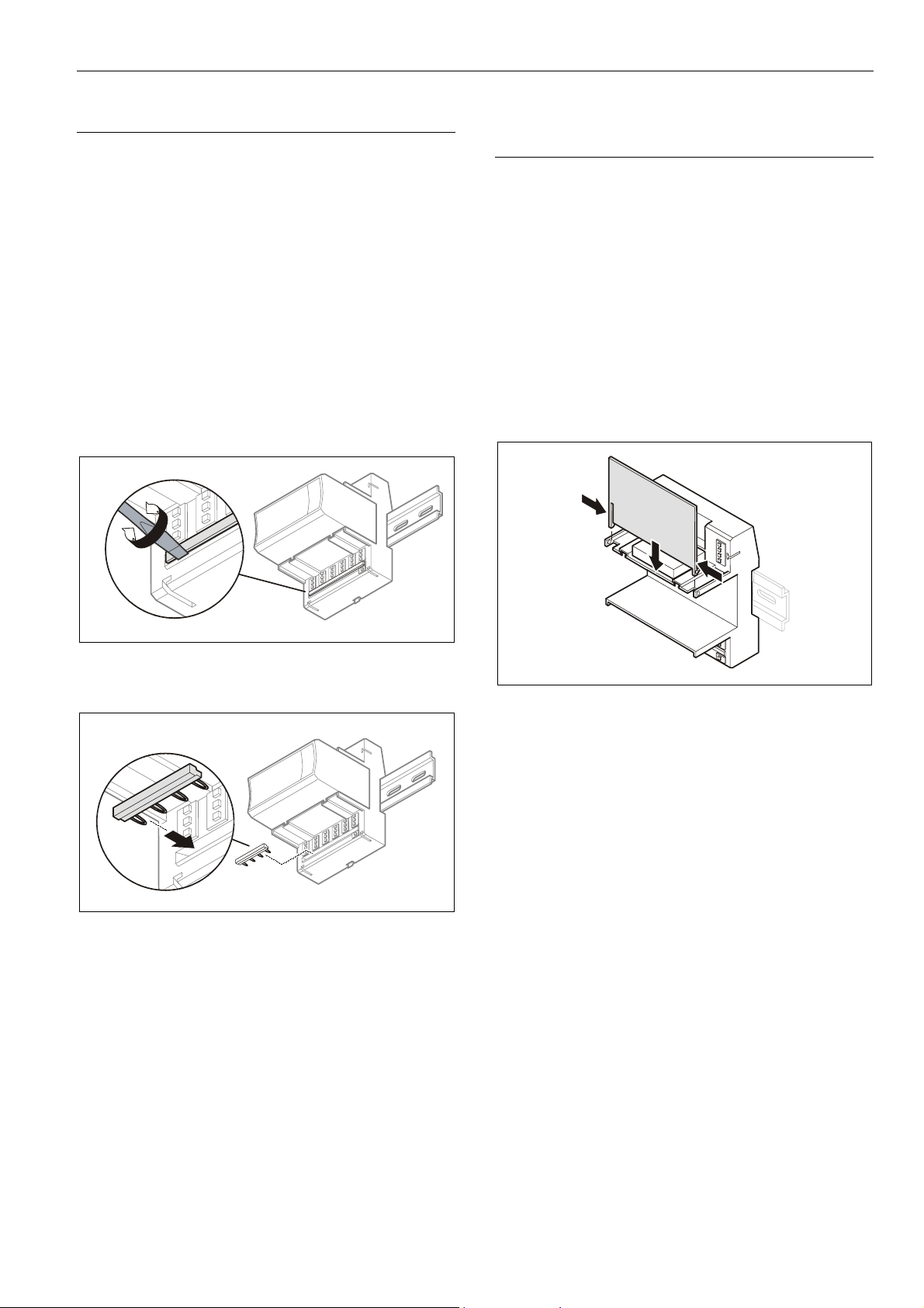
Mounting/Dismounting Swivel Label
Holders
Note
A swivel label holder is included in the scope of delivery of
each module.
Use only the (short / long) swivel label holders appropriate
for the given type (pluggable or mixed, respectively) of I/O
module.
Mounting Swivel Label Holders
► Snap the swivel label holder onto the hinges of the
terminal socket / mixed I/O module.
► Apply self-adhesive labels to the holders.
Fig. 28 Dismounting the cross connectors (long cross
connector shown here)
Fig. 29 Mounting the cross connectors (short cross
connector shown here)
Fig. 30 Mounting the swivel label holder
Dismounting Swivel Label Holders
► Press the hinges together and remove the swivel label
holder.
23 EN1Z-0921GE51 R0709
Wiring and Setting Up the System LION System
Wiring and Setting Up the System
General Safety Considerations
• When connecting the CLLIONLC01 or LION I/O modules,
both VDE, National Electric Code (NEC) or equivalent,
and any local regulations concerning grounding and zero
voltage must be observed.
• Electrical work should be carried out by a qualified
electrician.
• The electrical connections must be made at the terminal
blocks. The corresponding connection diagrams are
located on the individual controller module and
I/O modules.
• For Europe only: To comply with CE requirements,
devices with a voltage in the range of 50 ... 1000 VAC or
75 ... 1500 VDC, which are not provided with a supply
cord and plug or with other means for disconnection from
the supply having a contact separation of at least 3 mm
in all poles, must have the means for disconnection
incorporated in the fixed wiring.
WARNING
Risk of electric shock or equipment damage!
► Do not touch any live parts in the cabinet.
► Disconnect the power supply before making connections
to or removing connections from terminals of controller or
I/O modules.
► Do not use spare terminals as wiring support points.
► Do not reconnect the power supply until you have
completed the installation.
► Observe precautions for handling electrostatic sensitive
devices.
Wiring Push-in Terminals
The terminal sockets of the pluggable I/O modules are
available in versions (…82…) featuring convenient push-in
terminals for easy wiring. The CLIOP830A likewise features
push-in terminals.
For correct wiring, cables must fulfill the following
specifications according to IEC664-1 / VDE 0110 (4.97):
Max. plug gauge
Solid conductor H05/07) V-U
Stranded conductor H05(07) V-K
Stranded conductor with wire end
ferrules (without plastic collar)
Stripping length
Table 22 Push-in terminals wiring specifications
0.14 … 1.50 mm
0.25 … 1.50 mm
0.25 … 1.50 mm
0.25 ... 1.50 mm
8.0 +1.0 mm
Wiring Screw-Type Terminals
The terminal sockets of the pluggable I/O modules are also
available with screw-type terminals.
For correct wiring, cables must fulfill the following
specifications according to IEC664-1 / VDE 0110 (4.97):
Max. plug gauge
Solid conductor H05/07) V-U
Stranded conductor H05(07) V-K
Stranded conductor with wire end
ferrules (without plastic collar)
0.14 … 1.50 mm
0.25 … 1.50 mm
0.25 … 1.50 mm
0.25 ... 1.50 mm
2
2
2
2
2
2
2
2
Stripping length
Table 23 Screw-type terminals wiring specifications
EN1Z-0921GE51 R0709
24
11.0 +1.0 mm
LION System Wiring and Setting Up the System
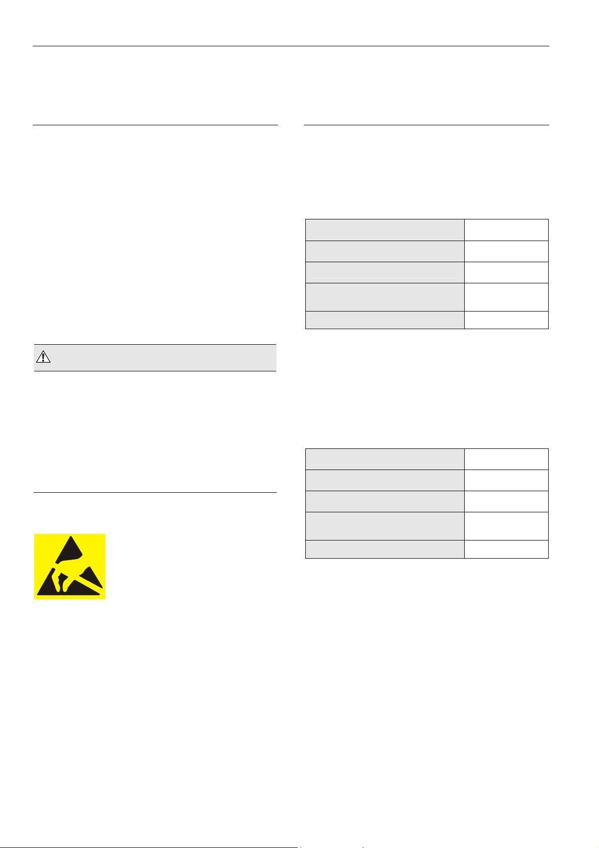
Connecting Power Supply
The LION System can be powered by one or more external
transformers.
Note
The maximum length for the power supply cable from a
transformer is 3 m. This also includes the length of the
modules and the connection cables between the rails.
Referring to Fig. 31 the following conditions must be fulfilled:
A + B ≤ 3 m and A + C ≤ 3 m
Single or the First Transformer
► Connect the transformer to terminals 1 and 2 of the
CLLIONLC01 Controller.
I/O I/O I/O
B C
A + B 3 m
AND
A + C 3 m
Fig. 31 Wiring power supply from the (first) transformer to
the controller module
CPU
21
A
Additional Transformer
► Connect the additional transformer in a second room or
cabinet to terminals 73 and 74 or 77 and 78 of an
I/O module.
TRANS-
FORMER 2
Fig. 32 Wiring the power supply from a second
71
72
73
74
MAX. 3 m
transformer
NOTICE
Equipment damage!
► Do not use bridge connectors to connect modules
powered by different transformers.
► When connecting modules powered by different
transformers using cables, be sure to not connect
terminals 73 and 77.
I/OI/O
25 EN1Z-0921GE51 R0709
Wiring and Setting Up the System LION System
Connecting Single Bus Controller Systems
This section describes how to connect a controller system
which uses Panel Bus I/O modules only or L
Bus I/O modules only.
Controller and I/O Modules on a Single Rail
► Connect controller and I/O modules using the bridge
connectors.
This provides power supply and communication connection.
No further wiring is necessary.
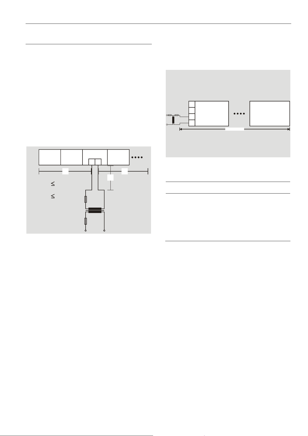
Controller and I/O Modules on Several Rails in a
Single Cabinet
The rails of a controller system are connected in series.
► Connect the rail ends as follows:
– Power supply
via power supply terminals 73, 74 or 77, 78
– Communication
via communication terminals 71, 72 or 75, 76
71
72
I/O
73
74
I/O
ONWORKS
Panel Bus I/O Modules in Separate Rooms
In this scenario, communication and reference voltage
(24 V0) must be connected between the rooms.
► Connect the last module of room 1 to the first module of
room 2:
– Reference voltage
via power supply terminals 74 or 78
terminals 73 and 77 must not be connected
– Communication
via communication terminals 71, 72 or 75, 76
75
CPU
PANE L
I/O
1 2
71
PANEL
I/O
PANE L
I/O
74
Fig. 34 Wiring the Panel Bus I/O modules in separate
rooms
76
77
78
75
7672
7773
78
24 V0
MAX. 40 m
I/OI/O
I/O
75
76
77
78
75
76
77
78
71
72
I/O
73
74
71
72
I/O
73
74
71
72
I/O
73
74
CPU
1 2
I/O
Fig. 33 Wiring the power supply and the communication
lines to the I/O modules
Maximum Power Cable Length
The maximum length for power supply cable per side is 3 m.
This also includes the connection cables between the rails,
the lengths of the modules, and the cable from the
transformer.
Maximum Cable Length
The maximum cable length for connecting room 1 and
room 2 is 40 m.
EN1Z-0921GE51 R0709
26

LION System Wiring and Setting Up the System
LonWorks Bus I/O Modules in Separate Rooms
In this scenario, only communication lines must be
connected between the rooms.
► Connect the last module of room 1 to the first module of
room 2:
– via communication terminals 71, 72 or 75, 76
75
CPU
1 2
71
LonWorks
I/O
74
Fig. 35 Wiring the LONWORKS Bus I/O modules in
separate rooms
Maximum Cable Length
For maximum cable lengths and cable specifications of the
communication lines, see Table 18 and Table 19 on
page 14.
LonWorks
I/O
LonWorks
I/O
76
77
78
75
7672
7773
78
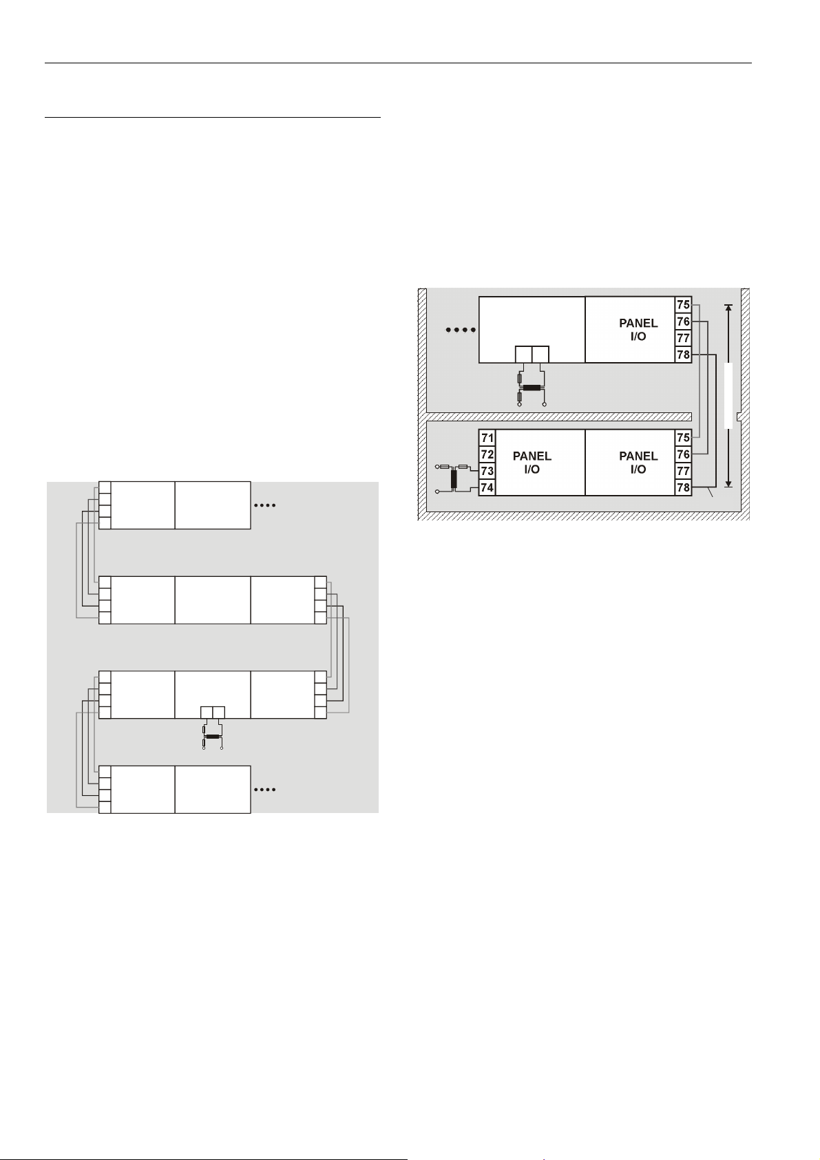
Connecting Panel Bus and LONWORKS Bus
Mixed Controller Systems
Connecting I/O Modules with Each Other
For connecting the I/O modules with each other, proceed as
described for single bus controller systems on page 25.
Connecting I/O Modules to the Controller
Panel Bus I/O Modules
► Connect communication terminals 71 …74 or 75… 78 of
Panel Bus I/O modules to communication terminals
71 …74 or 75… 78 of the controller module using either
– Bridge connectors
for flush mounting on a single DIN rail or
– Cables
for separate mounting,
e.g., on multiple rails, separate cabinets, etc.
L
ONWORKS Bus I/O Modules
► Connect communication terminals 71 … 74 or 75 … 78 of
L
ONWORKS Bus I/O modules to LONWORKS terminals
11 … 14 of the controller module using cables.
27 EN1Z-0921GE51 R0709
Wiring and Setting Up the System LION System
Panel Bus I/O modules Panel Bus I/O modules
71
72
73
74
71
75
72
76
73
77
74
78
71
75
72
76
73
77
74
78
75
76
77
78
XF...
LonWorks Bus I/O modules
71
72
73
74
71
75
72
76
73
77
74
78
71
75
72
76
73
77
74
78
75
76
77
78
Fig. 36 Mixed bus system – correct wiring
Panel Bus I/O modules LonWorks Bus modules
71
72
73
74
71
75
72
76
73
77
74
78
71
75
72
76
73
77
74
78
75
76
77
78
71
72
73
74
CLLIONLC01
11
12
13
14
71
72
CLLIONLC01
73
74
75
76
77
78
1
2
3
4
71
72
73
74
71
75
72
76
73
77
74
78
71
75
72
76
73
77
74
78
75
76
77
78
75
76
77
78
71
72
73
74
71
75
72
76
73
77
74
78
71
75
72
76
73
77
74
78
75
76
77
78
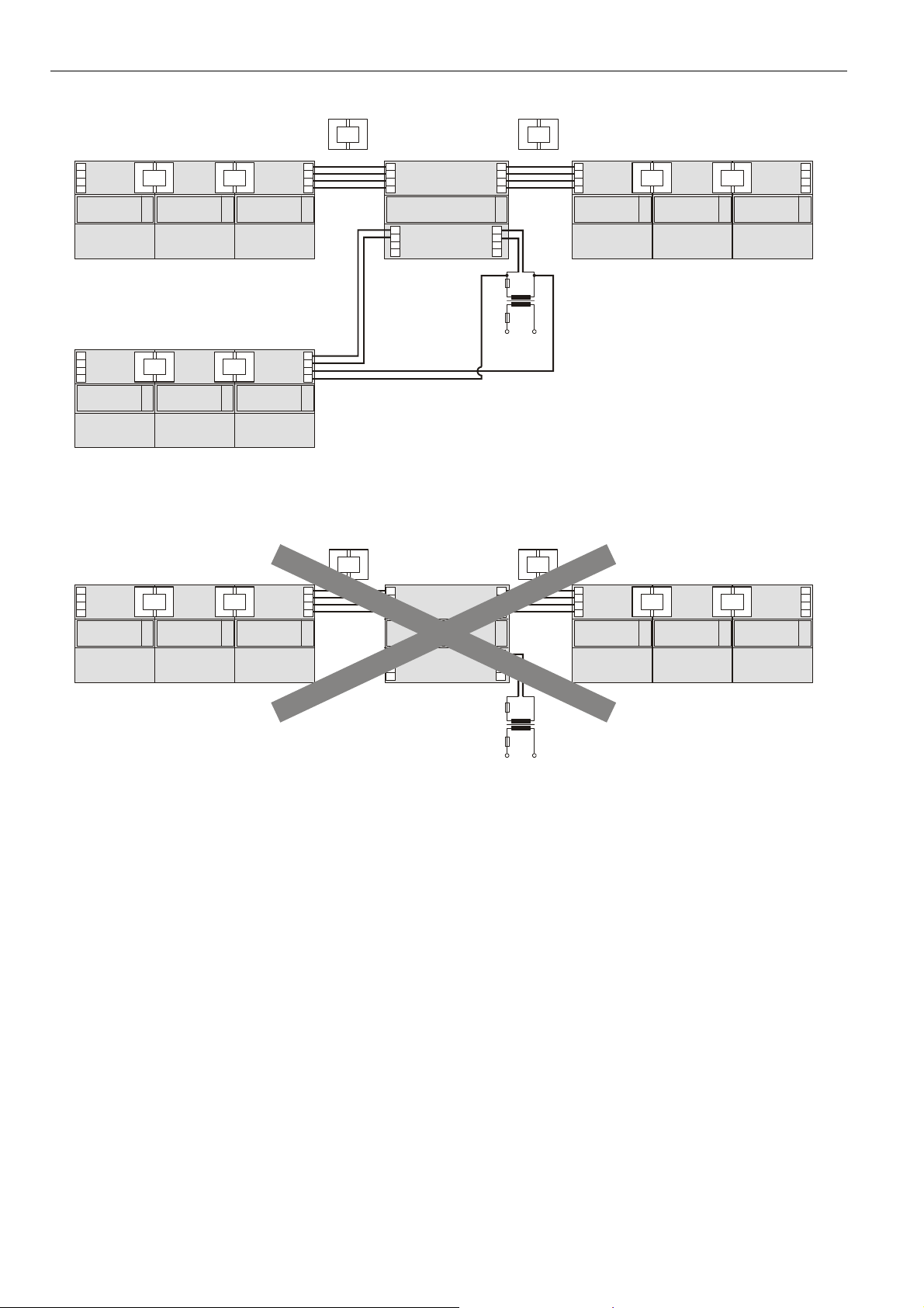
Fig. 37 Mixed bus system – incorrect wiring
11
12
13
14
1
2
3
4
EN1Z-0921GE51 R0709
28
 Loading...