

Honeywell CENTRA LINE EAGLEHAWK NX Installation & Commissioning Instructions

EAGLEHAWK NX Controller
TABLE OF CONTENTS
TABLE OF CONTENTS ......................................................... 1
Safety Information ................................................................ 2
General Safety Information ............................................... 2
Information as per EN 60730 ............................................ 2
WEEE Directive ................................................................ 2
Standards, Approvals, etc. ................................................ 2
3rd-Party Software Licenses ............................................... 2
Specifications of Controller ................................................. 3
System Overview .................................................................. 4
Overview of Hardware ...................................................... 4
System Architecture .......................................................... 5
Bus and Port Connections ................................................ 6
Set Up and Configuration .................................................. 12
General ........................................................................... 12
Procedure ....................................................................... 12
Configuring Ports to Enable Webserver Functions ......... 14
Firmware Update ............................................................ 15
Mounting/Dismounting ...................................................... 19
Before Installation ........................................................... 19
Dimensions ..................................................................... 19
Wiring and Set-Up .............................................................. 20
General Safety Considerations ....................................... 20
Lightning Protection ........................................................ 20
Wiring Terminals ............................................................. 20
Terminal Assignment ...................................................... 21
Power Supply .................................................................. 22
RIN-APU24 ..................................................................... 22
CLNXxxx26xxx Connection Examples ............................ 24
Internal I/Os of the EAGLEHAWK NX ............................. 2 6
Engineering, Commissioning ............................................ 29
Required Preparations .................................................... 29
Behavior of Outputs during Download ............................ 29
Extra Parts .......................................................................... 30
Software Licenses and Upgrades ..................................... 31
Panel Bus Connection ....................................................... 32
Overview of Panel Bus I/O Modules ............................... 32
Panel Bus Considerations ............................................... 32
Connecting EAGLEHAWK NX via its RS485-1 Interface to
a Panel Bus .................................................................... 33
Installation &
Commissioning
Instructions
Connecting EAGLEHAWK NX via its RS485-2 Interface to
a Panel Bus .................................................................... 34
Addressing Panel Bus I/O Modules ................................ 35
Automatic Updating of Panel Bus I/O Module Firmware 35
Cable Specifications ....................................................... 35
Tuning Panel Bus Communication ................................. 36
Field Devices .................................................................. 38
LonWorks Communications ............................................. 39
General Information ....................................................... 39
Connecting to a LONWORKS Network .............................. 39
BACnet MS/TP Bus Connection ....................................... 40
BACnet MS/TP Bus Considerations ............................... 40
Connecting EAGLEHAWK NX via its RS485-1 Interface to
a BACnet MS/TP Bus ..................................................... 40
Connecting EAGLEHAWK NX via its RS485-2 Interface to
a BACnet MS/TP Bus ..................................................... 42
Modbus Connection .......................................................... 43
Modbus Considerations .................................................. 43
Connecting EAGLEHAWK NX via its RS485-1 Interface to
a Modbus ....................................................................... 44
Connecting EAGLEHAWK NX via its RS485-2 Interface to
a Modbus ....................................................................... 45
M-Bus Connection ............................................................. 46
M-Bus Considerations .................................................... 46
M-Bus Connection Procedure ........................................ 47
Controller Performance ..................................................... 48
Troubleshooting ................................................................ 49
EAGLEHAWK NX Controller Troubleshooting ............... 49
Panel Bus I/O Module Troubleshooting .......................... 50
Appendix 1: Earth Grounding ........................................... 51
EAGLEHAWK NX Systems and SELV ........................... 51
EAGLEHAWK NX Systems and Standard EN60204-1 .. 51
Earth Grounding of EN60204-1 Applicable Systems ...... 51
Appendix 2 ......................................................................... 53
Sensor Input Accuracy ................................................... 53
Recognition of Sensor Failure of Sensor Inputs ............. 53
Sensor Characteristics ................................................... 53
Index ................................................................................... 56
Trademark Information
LON, L
ONWORKS, and Neuron are trademarks of Echelon
Corporation registered in the United States and other
countries.
® U.S. Registered Trademark
Copyright © 2018 Honeywell Inc. • All Rights Reserved EN1Z-1039GE51 R1218
EAGLEHAWK NX CONTROLLER – INSTALLATION & COMMISSIONING INSTRUCTIONS
SAFETY INFORMATION
General Safety Information
► When performing any work, all instructions given by the
manufacturer and in particular the safety instructions
provided in these Installation and Commissioning
Instructions are to be observed. Make sure that the local
standards and regulations are observed at all times.
► The EAGLEHAWK NX System (including the
EAGLEHAWK NX controller, Panel Bus I/O modules,
manual disconnect modules, and auxiliary terminal
packages) may be installed and mounted only by
authorized and trained personnel.
► If the controller housing is damaged or missing,
immediately disconnect it from any power.
► If the device is broken or defective, do not attempt to repair
it yourself; rather, return it to the manufacturer.
► It is recommended that devices be kept at room tem-
perature for at least 24 hours before applying power. This
is to allow any condensation resulting from low shipping /
storage temperatures to evaporate.
► The EAGLEHAWK NX System must be installed in such a
manner (e.g., in a lockable cabinet) as to ensure that
uncertified persons have no access to the terminals.
► In the case of vertical mounting on DIN rails, the
EAGLEHAWK NX controller should be secured in place
using a commercially-available stopper.
► If the EAGLEHAWK NX System is modified in any way,
except by the manufacturer, all warranties concerning
operation and safety are invalidated.
► Rules regarding electrostatic discharge should be followed.
► Use only accessory equipment which comes from or has
been approved by Honeywell.
Information as per EN 60730
Purpose
The purpose of the device is: OPERATING CONTROL. The
EAGLEHAWK NX controller is a multifunctional non-safety
control device intended for HVAC in home (residential,
commercial, and light-industrial) environments.
Construction
The EAGLEHAWK NX controller is an independently mounted
electronic control unit with fixed wiring.
Mounting Method
The EAGLEHAWK NX controller is suitable for mounting as
follows:
► in cabinets;
► in fuse boxes conforming with standard DIN43880, and
having a slot height of max. 45 mm;
► in cabinet front doors (using accessory MVC-80-AC2);
► on walls (using accessory MVC-80-AC1).
Table 1. Information as per EN 60730
Shock protection
Pollution degree
Installation
Rated impulse voltage
Automatic action
Software class
Ball-pressure test
temperature
Class II
2
Class 3
330 V for SELV, 2500 V for relay
outputs
Type 1.C (micro-interruption for
the relay outputs)
Class A
housing parts >75 °C
terminals >125 °C
WEEE Directive
WEEE: Waste Electrical and Electronic
Equipment Directive
At the end of the product life, dispose
of the packaging and product in an
appropriate recycling center.
Do not dispose of the device with the
usual domestic refuse.
Do not burn the device.
Standards, Approvals, etc.
Degree of Protection: IP20 (mounted on walls, with two
IP30 (mounted in cabinet doors, with
Device meets EN 60730-1, EN 60730-2-9, UL60730, and
UL916.
Refer to Code of Practice standards IEC 61000-5-1 and -2
for guidance.
The device complies with Ethernet Protocol versions IEEEC
802.3.
The device supports BACnet IP and BACnet MS/TP
communications as per ANSI / ASHRAE 135-2012.
accessory MVC-80-AC1 covers)
accessory MVC-80-AC2)
3RD-PARTY SOFTWARE LICENSES
This product contains software provided by third parties. See
also EAGLEHAWK NX Controller – Third-Party Software
Licenses (Product Literature No.: EN2Z-1041GE51).
EN1Z-1039GE51 R1218 2

EAGLEHAWK NX CONTROLLER – INSTALLATION & COMMISSIONING INSTRUCTIONS
SPECIFICATIONS OF CONTROLLER
Table 2. EAGLEHAWK NX specifications
Power supply
Power consumption
Heat dissipation
Current consumption
Ambient temperature
Storage temperature
Humidity
Dimensions
Degree of protection
Fire class
Weight
19 … 29 VAC, 50/60 Hz or
20 … 30 VDC
typically DC: 7 W; max. 9 W
typically AC: 10 VA; max. 12 VA
Max. 9 W at DC power supply
max. 9 W at AC power supply
typically DC: 300 mA; max. 375 mA
typically AC: 400 mA; max. 500 mA
0 … 40 °C (wall-mounting)
0 … 50 °C (cabinet/door mounting)
-20 … +70 °C
5 … 95% r.h. non-condensing
See Fig. 20 and Fig. 21.
IP20 (mounted on walls, with two accessory MVC-80-AC1 covers)
IP30 (mounted in cabinet doors, with accessory MVC-80-AC2)
V0
0.6 kg (excl. packaging)
3 EN1Z-1039GE51 R1218
EAGLEHAWK NX CONTROLLER – INSTALLATION & COMMISSIONING INSTRUCTIONS
SYSTEM OVERVIEW
Overview of Hardware
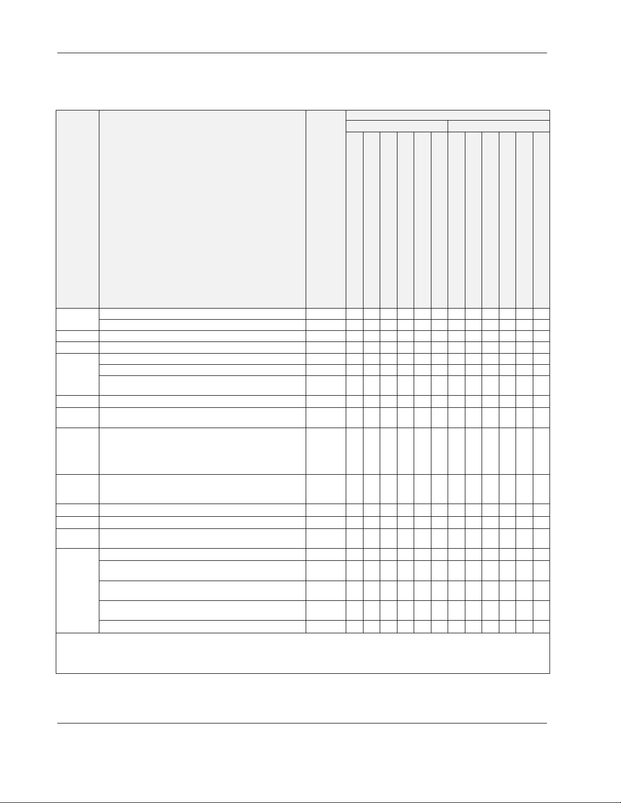
Table 3. Overview of models (hardware)
order no.
without HMI with HMI
feature description
UI
BI
AO
BO
total I/Os
bus
interfaces
LEDs
1)
Depending upon bit rate. However, in the case of configuration of RS485-2 for Panel Bus, the communication rate is set to
NTC10kΩ / NTC20kΩ / 0…10 V / slow BI, 0.4 Hz 400 m 0 0 4 4 8 8 0 0 4 4 8 8
NTC10kΩ / NTC20kΩ / 0…10 V fix pull-up / slow BI, 0.4 Hz 400 m 0 0 0 0 2 2 0 0 0 0 2 2
open = 24 V / closed 2.0 mA / totalizer 15 Hz 400 m 0 0 4 4 4 4 0 0 4 4 4 4
0..11 V (max. 1 mA) 400 m 0 0 2 2 4 4 0 0 2 2 4 4
Relay N.O. contact: 3 A, 250 VAC, 30 VDC 400 m 0 0 3 3 4 4 0 0 3 3 4 4
Relay N.O. contact (high in-rush): 10 A, 250 VAC, 30 VDC 400 m 0 0 1 1 1 1 0 0 1 1 1 1
Relay N.O. contact with one common: 3 A, 250 VAC,
30 VDC
-- 0 0 14 14 26 26 0 0 14 14 26 26
RS485-1, isolated, BACnet MS/TP, Panel Bus, or Modbus
RTU Master or Slave communication
RS485-2, non-isolated, BACnet MS/TP, Panel Bus, or
Modbus RTU Master or Slave communication (NOTE: It is
imperative that the RS485-2 be powered by a power supply
having the proper polarity. Failure to do so will make data
transmission impossible.)
Ethernet Interfaces (e-mail communication, browser
access, BACnet IP communication, Niagara Network,
Modbus TCP)
USB 2.0 Device Interface (as Network Interface) 3 m 1 1 1 1 1 1 1 1 1 1 1 1
USB 2.0 Host Interface (max. 200 mA) 3 m 1 1 1 1 1 1 1 1 1 1 1 1
RS232 M-Bus communication via 15-meter-long PW3 /
PW20 / PW60 converters
power LED (green)
status LED (red; indicates an active alarm; is controlled by
Niagara Alarm System; is configurable)
LED L1 (yellow; lit = Daemon starting; flashing = station
starting; if L2 is also flashing, then the station has started)
LED L2 (yellow; lit = platform has started / is reachable;
flashing = station has started / is reachable)
bus status LEDs (for isolated RS485-1 interface)
max.
cable
length
CLNXEH00ND100A, CLNXEHSERIES00ND
CLNXEHS00ND100A
CLNXEH14ND100A, CLNXEHSERIES14ND
CLNXEHS14ND100A
CLNXEH26ND100A, CLNXEHSERIES26ND
CLNXEHS26ND100A
CLNXEH00D100A, CLNXEHSERIES00D
CLNXEHS00D100A
CLNXEH14D100A, CLNXEHSERIES14D
400 m 0 0 0 0 3 3 0 0 0 0 3 3
1)
1200 m 1 2)11 2)11 2)1 1 2)1 1 2)11 2)1
1)
1200 m 1 2)11 2)11 2)1 1 2)1 1 2)11 2)1
100 m 2 2 2 2 2 2 2 2 2 2 2 2
1)
1000 m 1 1 1 1 1 1 1 1 1 1 1 1
1 1 1 1 1 1 1 1 1 1 1 1
--
1 1 1 1 1 1 1 1 1 1 1 1
--
1 1 1 1 1 1 1 1 1 1 1 1
--
1 1 1 1 1 1 1 1 1 1 1 1
--
2 2 2 2 2 2 2 2 2 2 2 2
--
CLNXEHS14D100A
115.2 kbps, and the max. cable length is hence 800 m.
2)
In the case of these devices, for Panel Bus functionality, an additional license must be purchased (see Table 19).
CLNXEH26D100A, CLNXEHSERIES26D
CLNXEHS26D100A
EN1Z-1039GE51 R1218 4
EAGLEHAWK NX CONTROLLER – INSTALLATION & COMMISSIONING INSTRUCTIONS
A
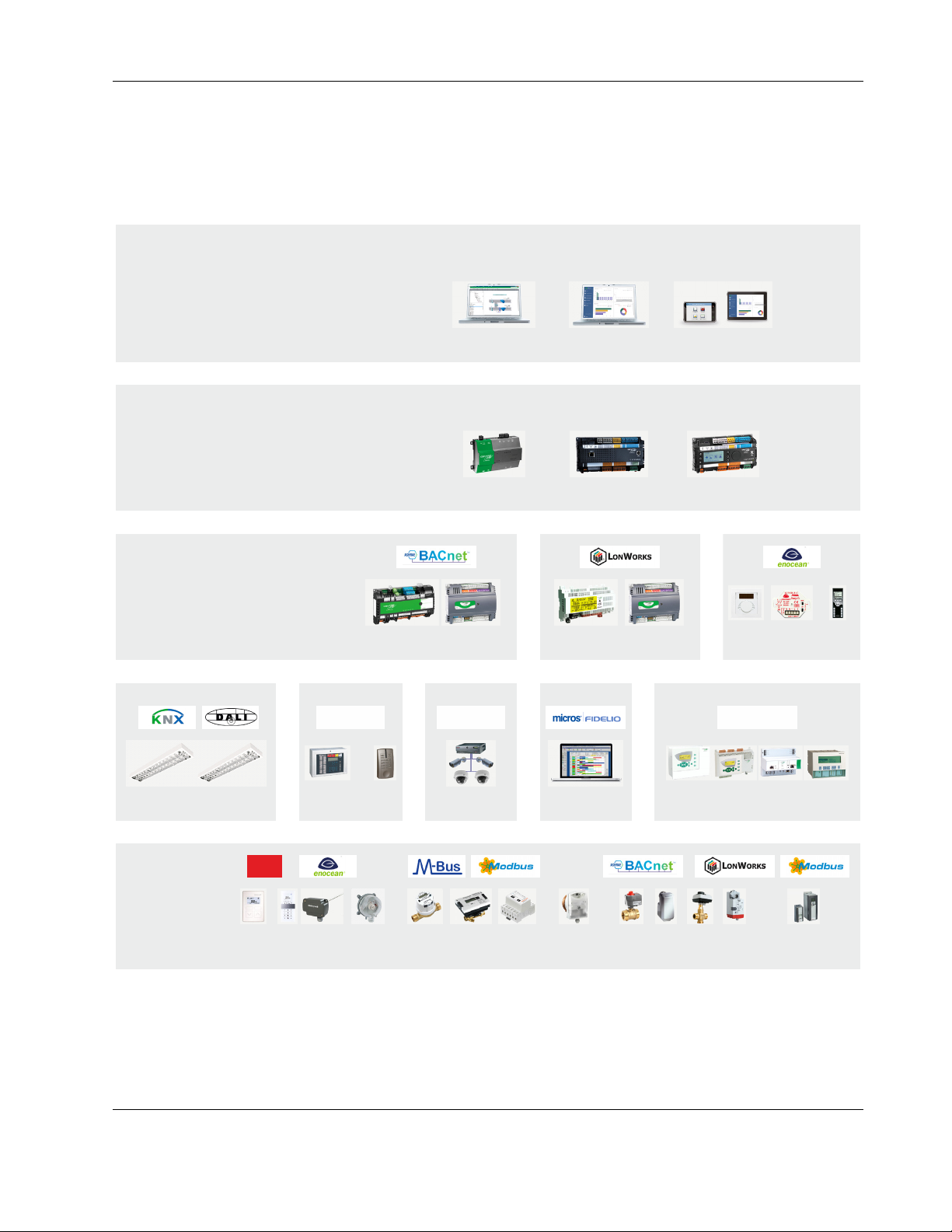
System Architecture
An EAGLEHAWK NX System consists of the EAGLEHAWK NX controller and various Panel Bus I/O modules. The
EAGLEHAWK NX controller provides interface connections, which allow connection to external systems (e.g., BACnet
controllers). Via the IF-LON External Interface, the EAGLEHAWK NX can also communicate with L
CentraLine L
ONWORKS I/O Modules.
ONWORKS systems, including
Auxiliary parts (see section "Extra Parts" on page 30) enable special features.
SUPERVISION AND ENERGY MANAGEMENT
RENA NX
INTEGRATION AND HVAC PLANT CONTROL
HAWK 8000
ROOM MANAGEMENT
MERLIN
LYNX
ARENA NX ENERGY
EAGLEHAWK NX
SERVAL EASY CLICK
LYNX
MOBILE
EAGLE
LIGHTING, SHADING, TEMP.
LEGACY HVAC
C-BUSTCP/IPTCP/IP
LIGHTING FIRE & SECURITY VIDEO
FIELD
LYNX
Sylk
HOTEL
RESERVATIONS
PANTHER TIGER LION EXCEL 5000
DEVICES
SENSORS METERS
THERMO-
STATS
Fig. 1. NX – Niagara eXtended Integrated Building Management architecture
5 EN1Z-1039GE51 R1218
VALVES AND
ACTUATORS
VARIABLE-SPEED
DRIVES
EAGLEHAWK NX CONTROLLER – INSTALLATION & COMMISSIONING INSTRUCTIONS
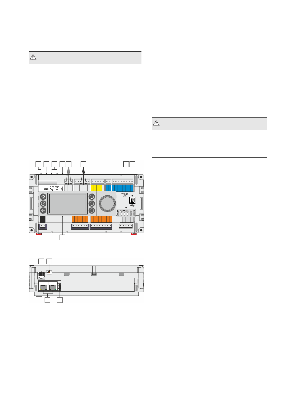
Bus and Port Connections
Overview
WARNING
Risk of electric shock or equipment damage!
► Do not touch any live parts in the cabinet!
► Disconnect the power supply before making connections
to or removing connections from terminals of the
EAGLEHAWK NX controller or Panel Bus I/O modules.
► Do not reconnect the power supply until you have
completed installation.
► Due to the risk of short-circuiting (see Fig. 23), it is
strongly recommended that the EAGLEHAWK NX controller be supplied with power from a dedicated transformer. However, if the EAGLEHAWK NX controller is to
be supplied by the same transformer powering other controllers or devices (e.g., the PW M-Bus Adapter), care
must be taken to ensure that correct polarity is observed.
► Observe the rules regarding electrostatic discharge.
1 2 3 4
5
6
7 8
3 Two Ethernet / RJ45 sockets (for BACnet IP com-
munication); 10/100 Mbit/s; 1 "link" LED + 1 "activity"
LED
4 USB 2.0 Host Interface (for connection of IF-LON2);
max. 200 mA, high speed
5 RS485-1* (isolated; for BACnet MS/TP, Panel Bus,
Modbus RTU communication, etc.)
6 RS485-2* (non-isolated; for BACnet MS/TP, Panel
Bus, Modbus RTU communication, etc.)
7 LEDs
8 USB 2.0 Device Interface (for connection to COACH
NX web browsers, and 3
rd
-party touch panels)
9 HMI (or RJ45 socket for connection of portable HMI)
*Modbus RTU Master/Slave communication is possible on the
two RS485 interfaces.
WARNING
Risk of electric shock or equipment damage!
► It is prohibited to connect any of the RJ45 sockets of the
EAGLEHAWK NX controller to a so-called PoE-enabled
device ("Power over Ethernet").
21
END
BIAS
MID
RS232
RS485-1
24V~
24V-0
1
2
24 25 26 27 28 29 30 31 32
n.a.
485-1-
485-1+
GND1
DO1
DO2
5 6 7 8 9 10 1112131415161718 19202122
33 34 35 36 37 38 39 40 41 42 43 44 45 46
BI1
BI2
n.a.
485-2+
IN
DO3
BI3
n.a.
485-2-
GND2
IN4
IN5
IN6
DO5
DO4
UI1
BI4
UI9
UI10
GND
IN7
IN8
DO6
DO7
DO8
47
UI2
UI3
UI4
UI5
UI6
UI7
UI8
AO1
AO2
AO3
AO4
GND
23
9
Fig. 2. Top view (with HMI and full complement of
onboard I/Os)
1 2
END
BIAS
MID
3
4
Fig. 3. Side view
Legend
1 RS232 / RJ45 socket (for connection of M-Bus and
other RS232-based protocols; factory debugging)
2 Three-position slide switch (for setting bias and
termination resistance of RS485-1)
EN1Z-1039GE51 R1218 6
EAGLEHAWK NX CONTROLLER – INSTALLATION & COMMISSIONING INSTRUCTIONS
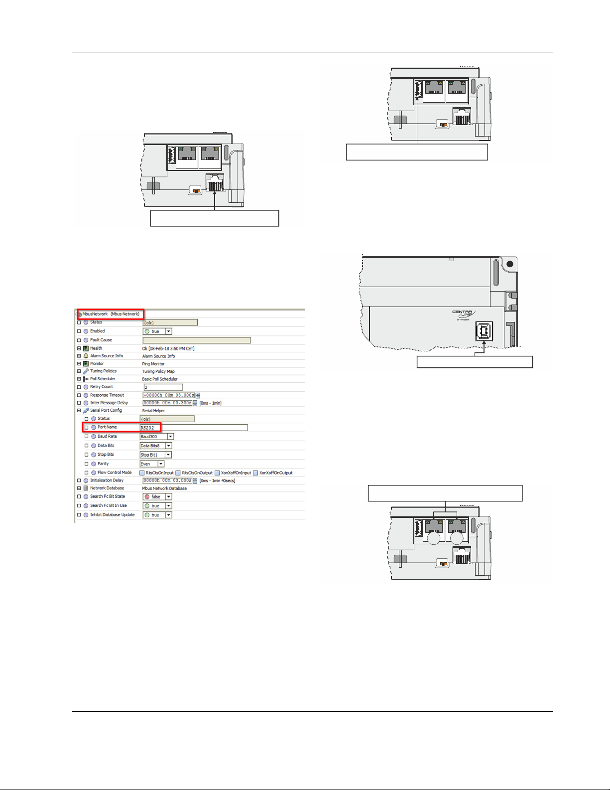
RS232 / RJ45 Socket
Via its RS232 / RJ45 socket, the EAGLEHAWK NX controller
can be connected (using an XW586 cable) to a PW M-Bus
Adapter and thus to M-Bus networks. See also section "MBus Connection" on pg. 46.
END
BIAS
MID
END
BIAS
MID
RS232-RJ45 SOCKET
Fig. 4. RS232 / RJ45 socket
Configuring the RS232 Interface in COACH NX
When you configure the RS232 interface (for M-Bus) in
COACH NX, the corresponding Port Name will appear as
shown in Fig. 5.
USB 2.0 HOST INTERFACE
Fig. 6. USB 2.0 Host interface
USB 2.0 Device Interface
All models of the EAGLEHAWK NX controller are equipped
with a USB 2.0 Device Interface at the front. This interface is
for connection to COACH NX and web browsers, or 3
touch panels.
USB 2.0 DEVICE INTERFACE
Fig. 7. USB 2.0 Device Interface
A standard USB type-B connector can be inserted into this
USB 2.0 Device Interface. This USB 2.0 Device Interface is
the recommended interface for connection to COACH NX.
Ethernet / RJ45 Sockets
The EAGLEHAWK NX controller is equipped with two
Ethernet / RJ45 sockets, each featuring two LEDs.
rd
-party
ETHERNET / RJ45 SOCKETS
Fig. 5. Configuring the RS232 Interface in COACH NX
USB 2.0 Host Interface
Via its USB 2.0 Host interface, the EAGLEHAWK NX controller can be connected to, e.g., the IF-LON2 External Interface Adapter and thus to L
high speed. See also section "LonWorks Communications" on
pg. 39.
7 EN1Z-1039GE51 R1218
ONWORKS networks. Max. 200 mA,
Fig. 8. Ethernet / RJ45 sockets
The two Ethernet / RJ45 sockets are 10/100-Mbit/s Ethernet
interfaces permitting communication (as per IEEEC 802.3) on
any supported IP network, e.g.: BACnet (IP), FOX, etc.
INTERFACE 1
INTERFACE 2
END
BIAS
MID
EAGLEHAWK NX CONTROLLER – INSTALLATION & COMMISSIONING INSTRUCTIONS
RIGHT (YELLOW) LED
LIT CONTINUOUSLY = "100 Mbaud"
DARK = "10 Mbaud "
INTERFACE 1
LEFT (GREEN) LED
LIT CONTINUOUSLY = LINK ACT IVE
DARK = " "
""
LINK INACTIVE
INTERFACE 2
Fig. 9. Ethernet / RJ45 sockets
NOTE: The Ethernet / RJ45 sockets are usually earth-
grounded. For additional information, see also
"Appendix 1: Earth Grounding" on pg. 51.
The two Ethernet interfaces can be used in either of two
different ways (the corresponding configuration is done in
COACH NX):
• "Separated networks" (factory default). In this scenario,
each of the two Ethernet interfaces must be activated and
located in a different subnet.
• "Switch functionality." In this scenario, one of the two
Ethernet interfaces is deactivated. The deactivated Ethernet interface now functions in the loop-through (daisychain) mode and can therefore be used to continue the
data line.
NOTE: During any power failure of the EAGLEHAWK NX,
the switching functionality is inoperative.
TCP/IP Configuration
Host Name
Host File
DNS Domain
IPv4 Gateway
192.168.1.1
DNSv4 Servers
Interfaces
Interface 1
Interface 2
ID
Description
Physical Address
Adapter Enabled
Ipv4 Settings
DHCPv4
IPv4 Address
IPv4 Subnet Mask
DHCPv4 Server
fec1
Local Ethernet Adapter 2
00:30:AF:FF:04:61
Enabled
Ipv6 Settings
Enabled
Application Director
Certificate Management
Distribution File Installer
File Transfer Client
Lexicon Installer
License Manager
Platform Administration
Software Manager
Station Copier
TCP/IP Configuration
Remote File System
Fig. 10. Entering gateway address, disabling one of the
two Ethernet interfaces in COACH NX
To ensure that the discovery of devices, datapoints,
schedules, and histories does not fail, you should enter a
gateway address. If there is no gateway address physically
given by the Network Setting, then enter a gateway address
that relates to the IP address of the enabled Ethernet Interface. In Fig. 10, the gateway address is 192.168.1.1, hence
the IP address of Ethernet adapter 1 must be in the range of
192.168.1.2 to 192.168.1.255.
Default IP Addresses of Ethernet Interfaces 1 and 2
In any case, the default IP address of Ethernet interface 1 is:
192.168.200.20, mask 255.255.255.0
and the default IP address of Ethernet interface 2 is:
192.168.201.20, mask 255.255.255.0
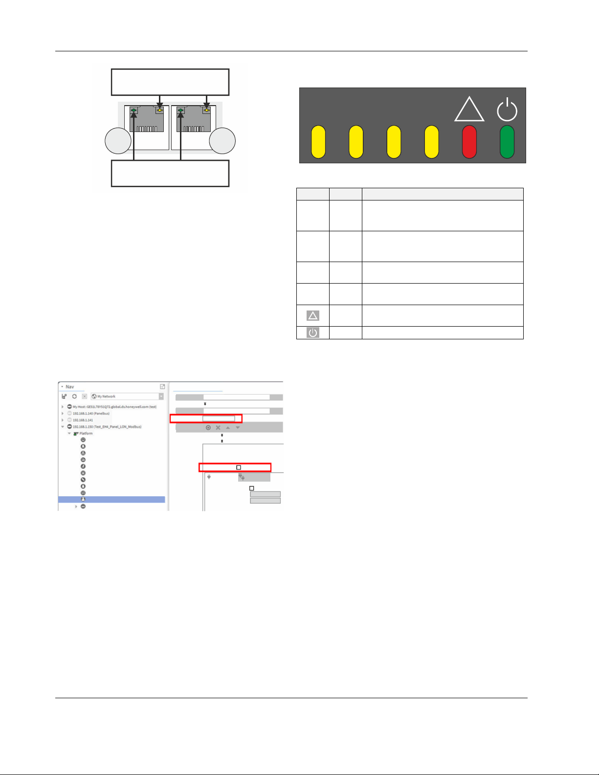
LEDs
The EAGLEHAWK NX controller features the following LEDs:
L1 L2
Tx Rx
!
Fig. 11. EAGLEHAWK NX controller LEDs
Table 4. EAGLEHAWK NX controller LEDs
symbol
color function, description
Lit = Daemon starting; flashing = station
L1 yellow
starting; if L2 is also flashing, then the
station has started.
Lit = platform has started / is reachable;
L2 yellow
flashing = station has started / is
reachable.
Tx yellow
Rx yellow
!
red
RS485-1 status LED indicating transmission of communication signals.
RS485-1 status LED indicating reception
of communication signals.
Indicates an active alarm; is controlled by
Niagara Alarm System; is configurable.
green Power LED.
See also section "EAGLEHAWK NX Controller Troubleshooting" on page 49 for a detailed description of the
behaviors of the LEDs and their meanings.
RS485 Interfaces
General
The EAGLEHAWK NX controller features two RS485
interfaces:
• RS485-1 (consisting of push-in terminals 24 [GND-1], 25,
and 26) is isolated and can be used for any RS485-based
communication protocol available within Niagara
Ecosystems, e.g.: Panel Bus, BACnet MS/TP, etc.
• RS485-2 (consisting of push-in terminals 29, 30, and 31
[GND-2]) is non-isolated (i.e. GND-2 is internally connected with terminal 1 [24V~0]) and can be used for any
RS485-based communication protocol available within
Niagara Ecosystems, e.g.: Panel Bus, BACnet MS/TP,
etc.
NOTE: It is imperative that the RS485-2 be powered by a
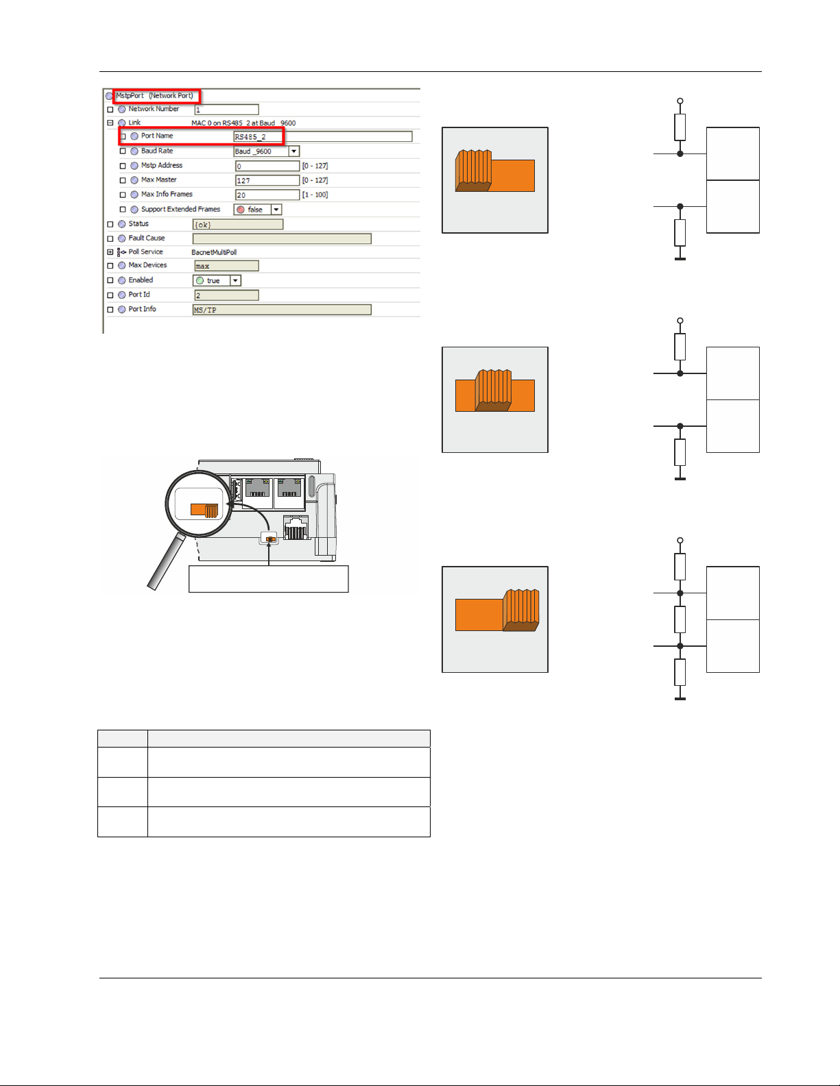
Configuring the RS485 Interfaces in COACH NX
When you configure the two RS485 interfaces (for Modbus,
BACnet MS/TP, or Panel Bus) in COACH NX, the corresponding Port Names will appear as shown in Fig. 12.
power supply having the proper polarity. Failure to do
so will make data transmission impossible.
EN1Z-1039GE51 R1218 8
EAGLEHAWK NX CONTROLLER – INSTALLATION & COMMISSIONING INSTRUCTIONS
A
+5V
ISO
Fig. 12. Configuring the RS485 interfaces in COACH NX
RS485-1 Bias and Termination Resistors
RS485-1 is equipped with a three-position slide switch which
can be used to switch its bias resistors OFF (position "MID" –
this is the default), ON (position "BIAS"), and ON with an
additional 150Ω termination resistor (position "END").
END
BIAS
MID
END
BIAS
MID
MID (DEFAULT)
47 kOHM
RS485-1 (+)
END
BIAS
MID
RS485-1 (-)
47 kOHM
GND-1
Fig. 14. RS485-1 three-position slide switch setting MID
+5V
ISO
550 OHM
BIAS
RS485-1 (+)
END
BI
MID
S
RS485-1 (-)
550 OHM
GND-1
Fig. 15. RS485-1 three-position slide switch setting BIAS
+5V
ISO
25
26
25
26
3-POSITION SLIDE SWITCH
Fig. 13. RS485-1 three-position slide switch
The recommended slide switch setting depends upon the
location and usage of the given EAGLEHAWK NX – see Fig.
14 through Fig. 16 and Table 5; it also depends upon the
selected communication protocol (BACnet MS/TP, Panel Bus,
or Modbus RTU Master communication, respectively).
Table 5. Recommended slide switch settings
setting remarks
END
BIAS
MID
Controllers located on either end of bus should have
this setting.
In small bus networks, a min. of one and a max. of
two controllers should have this setting.
All other controllers (not set to "END" or "BIAS") on
bus should have this setting (which is the default).
RS485-1
550 OHM
END
MID
BIAS
END
RS485-1 (+)
150 OHM
RS485-1 (-)
550 OHM
GND-1
Fig. 16. RS485-1 three-position slide switch setting END
NOTE: All terminals are protected (up to 24 VAC) against
NOTE: According to BACnet standards, a minimum of one
short-circuiting and incorrect wiring – except when
the 3-position slide switch is set to "END," in which
case the terminals of the RS485-1 bus (24, 25, and
26) have no such protection. Higher voltages may
damage the device.
and a maximum of two BACnet devices must have
its/their bias resistors switched ON. In the case of
the RS485-1 interface of the EAGLEHAWK NX,
setting its slide switch to either "BIAS" or "END"
fulfills this requirement.
25
26
9 EN1Z-1039GE51 R1218
EAGLEHAWK NX CONTROLLER – INSTALLATION & COMMISSIONING INSTRUCTIONS
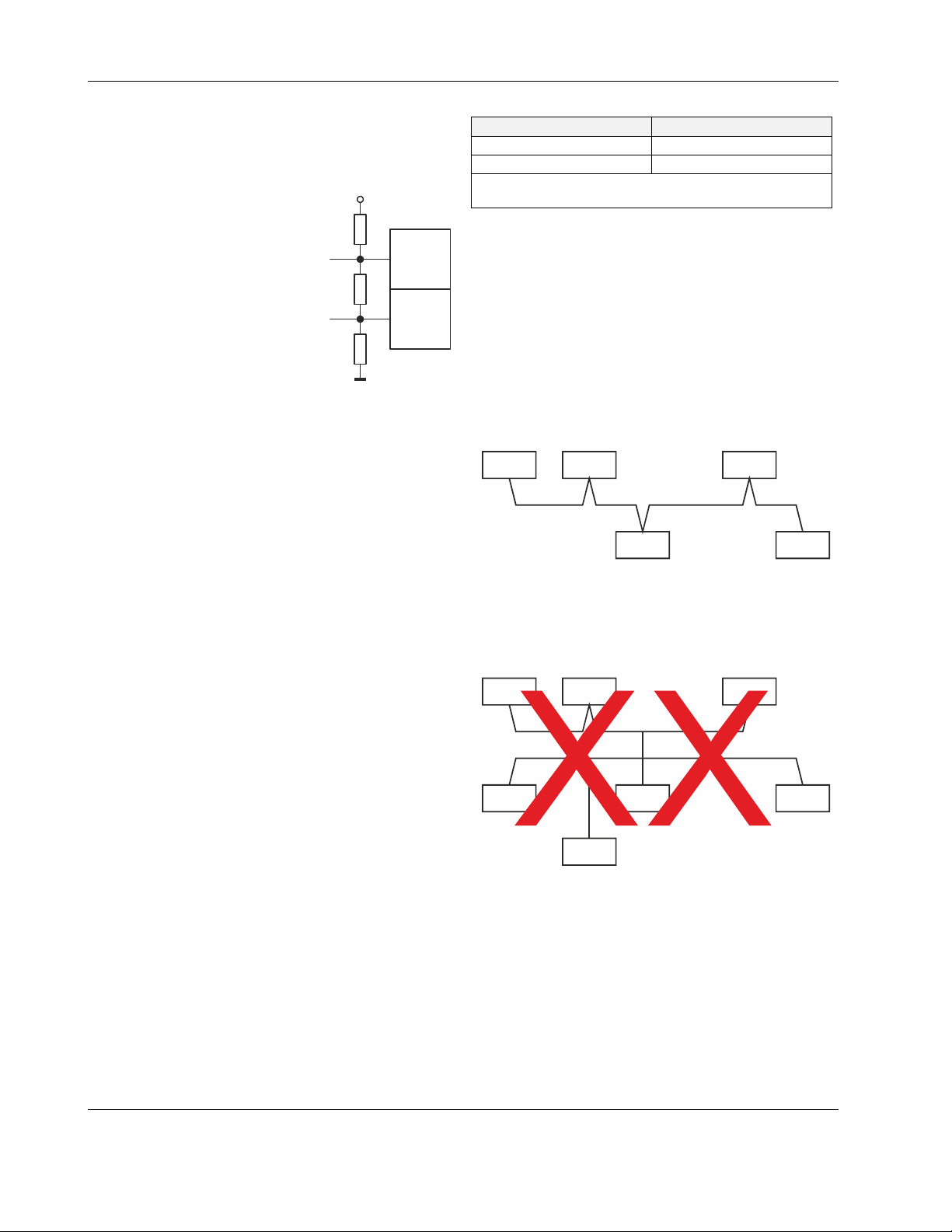
RS485-2 Bias and Termination Resistors
The RS485-2 interface is not affected by the aforementioned
three-position slide switch. The 550Ω bias resistors and 130Ω
termination resistor of the RS485-2 are thus always ON.
+5V
550 OHM
RS485-2 (+)
30
130 OHM
RS485-2 (-)
31
550 OHM
GND-2
Fig. 17. RS485-2 bias and termination resistors
NOTE: GND-2 is internally connected with 24V-0
RS485 Standard
According to the RS485 standard (TIA/EIA-485: "Electrical
Characteristics of Generators and Receivers for Use in
Balanced Digital Multipoint Systems"), only one driver communicating via an RS485 interface may transmit data at a
time. Further, according to U.L. requirements, each RS485
interface may be loaded with a max. of 32 unit loads. E.g.,
CentraLine devices have as little as ¼ unit load each, so that
up to 128 devices can be connected.
BACnet MS/TP connections to the RS485 interfaces must
comply with the aforementioned RS485 standard. Thus, it is
recommended that each end of every connection be equipped
with one termination resistor having a resistance equal to the
cable impedance (120 Ω / 0.25 – 0.5 W).
RS485 systems frequently lack a separate signal ground wire.
However, the laws of physics still require that a solid ground
connection be provided for in order to ensure error-free
communication between drivers and receivers – unless all of
the devices are electrically isolated and no earth grounding
exists.
IMPORTANT
The cable length affects the communication rate. Table 6
provides a few examples.
(terminal 1)
In the case of new EAGLEHAWK NX controller
installations, we strongly recommend using a separate
signal ground wire. Doing otherwise may possibly lead
to unpredictable behavior if other electrically nonisolated devices are connected and the potential
difference is too high.
In the case of the installation of EAGLEHAWK NX
controllers in already-existent RS485 two-wire systems
(e.g., when replacing PANTHER and LION controllers
with EAGLEHAWK NX controllers), not using a
separate signal ground wire will probably have no
undesirable effects.
Table 6. Bit rate vs. max. cable length for RS485
Bit rate Max. cable length (L)
9.6 - 76.8 kbps 1200 m
*115.2 kbps 800 m
* In the case of configuration of RS485-2 for Panel Bus, the
communication rate is set to 115.2 kbps.
For information on wire gauge, max. permissible cable length,
possible shielding and grounding requirements, and the max.
number of devices which can be connected to a bus, refer to
standard EIA-485.
Modbus Connection
The EAGLEHAWK NX controller can function as a Modbus
Master or Slave. In general, the RS485 wiring rules must be
followed.
Wiring Topology
Only daisy-chain wiring topology is allowed.
MODBUS
MASTER
Other wiring topologies (e.g., star wiring, or mixed star wiring
and daisy chain wiring) are prohibited; this is to avoid communication problems of the physical layer.
MODBUS
MASTER
MODBUS
SLAVE
Fig. 19. Prohibited Modbus wiring topology (example)
Cables
See also section "EIA 485 Cable Specifications" on pg. 35.
Use shielded twisted pair cable J-Y-(St)-Y 2 x 2 x 0,8.
You must use three wires:
• One wire for D1 = Modbus +
• One wire for D0 = Modbus –
• One wire for the signal common
When using one pair for D1 and D0 and one wire of another
pair for the signal common, CAT5 cable may also be used.
MODBUS
SLAVE
MODBUS
SLAVE
Fig. 18. Allowed Modbus wiring topology
MODBUS
SLAVE
MODBUS
SLAVE
MODBUS
SLAVE
MODBUS
SLAVE
MODBUS
SLAVE
MODBUS
SLAVE
MODBUS
SLAVE
EN1Z-1039GE51 R1218 10

EAGLEHAWK NX CONTROLLER – INSTALLATION & COMMISSIONING INSTRUCTIONS
For connection details, see section "Modbus Connection" on
pg. 43.
Shielding
Shielding is especially recommended when the Modbus cable
is installed in areas with expected or actual electromagnetic
noise. Avoiding such areas is to be preferred.
Use shielded twisted pair cable shielded twisted pair cable JY-(St)-Y 2 x 2 x 0,8 and connect the Modbus to a noise-free
earth ground – only once per Modbus connection.
RS485 Repeaters
RS485 repeaters are possible, but have not been tested by
Honeywell. Hence it is within responsibility of the installing /
commissioning person to ensure proper function.
NOTE: Each Modbus segment will require its own line
Modbus Master Specifications
Modbus Compliance
As per the Modbus standard, the EAGLEHAWK NX controller
is a conditionally compliant "regular" Modbus device.
The EAGLEHAWK NX controller differs from an unconditionally compliant "regular" Modbus device in that it does not
support communication rates of 1.2, 2.4, and 4.8 kbps
(because these communication rates are not marketrelevant).
Physical Layer
2-wire serial line RS485 (EIA-485) (with additional common)
Communication rates: 9.6, 19.2, 38.4, 57.6, 76.8, and
Max. number of devices: 32
Cable and wiring specifications: See section "Wiring and Set-
Up" on pg. 20.
Communication Mode
Typically: Modbus Master.
Transmission Mode
RTU (Remote Terminal Unit) and (via Ethernet) TCP/IP.
Address Range
Modbus slaves can have an address between 1 and 247.
Discrete Inputs, Coils, Input Registers and Holding Registers
can have an address between 1 and 65534.
Further Information
For further information, please refer to the Modbus Driver
documentation (docModbus.pdf).
polarization and line termination.
115.2 kbps supported.
11 EN1Z-1039GE51 R1218

EAGLEHAWK NX CONTROLLER – INSTALLATION & COMMISSIONING INSTRUCTIONS
SET UP AND CONFIGURATION
General
You can access the EAGLEHAWK NX controller via the
RS232 interface using a terminal program (serial port) such
as "PuTTY." This can be helpful in the following cases:
• When the EAGLEHAWK NX controller cannot be
accessed via network. Solution: The network can be
configured to the required settings (see step 6 below).
• When the EAGLEHAWK NX controller application or
status is unknown Solution: The controller can be reset to
the factory defaults (see step 7 below).
Before proceeding (see section "Procedure" below), you must
first connect the RS232 interface of the EAGLEHAWK NX
controller and the PC on which PuTTY is running using the
following two cables connected end-to-end: XW586 and
XW585.
The interface parameters for serial communication are as
shown in the following screenshot:
2. To login and change the IP address and/ or configure
further network settings, press 1.
RESULT: You will be asked to enter your username.
Procedure
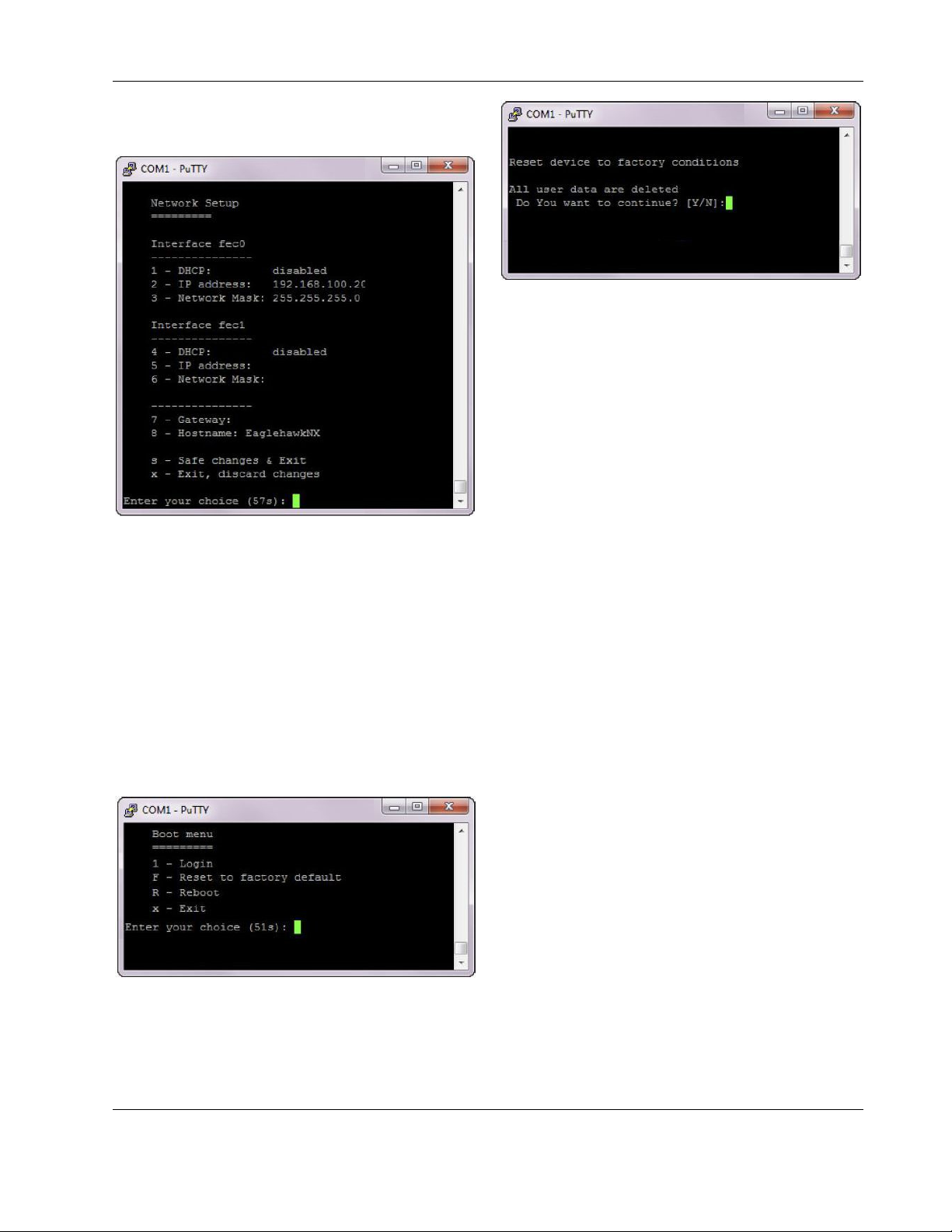
1. Start PuTTY. As soon as the following line displays,
press c.
3. Enter the user name and press Enter.
RESULT: You will be asked to enter your password.
4. Enter the password and press Enter.
RESULT: The Main menu displays.
RESULT: The Boot menu displays.
EN1Z-1039GE51 R1218 12
EAGLEHAWK NX CONTROLLER – INSTALLATION & COMMISSIONING INSTRUCTIONS
5. Press 1 in the Main menu.
RESULT: The Network Setup displays.
6. Configure the network as desired by applying the available
options displayed.
7. To reset the controller to factory defaults, press F in the
Boot menu.
ATTENTION: Resetting the controller to its factory
defaults will result in the following:
• The station will be deleted.
• The platform credentials will be deleted.
• The IP settings will be reset to the factory defaults (see
section "Default IP Addresses of Ethernet Interfaces 1 and
2" on pg. 8).
RECOMMENDATION: Before leaving (closing) the terminal
program, go to "Network Setup" and
enter the desired IP settings.
FINISHED!
8. Reset the controller by entering Y.
13 EN1Z-1039GE51 R1218
EAGLEHAWK NX CONTROLLER – INSTALLATION & COMMISSIONING INSTRUCTIONS
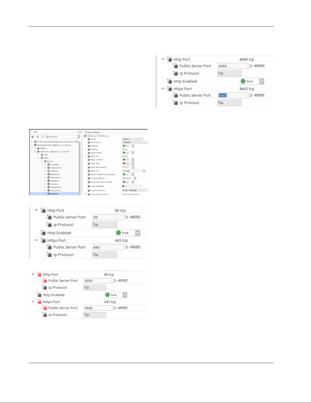
Configuring Ports to Enable Webserver
Functions
The EAGLEHAWK NX controller provides webserver functionality, e.g., for using the CentraLine N4 Supervisor. In order
to use webserver functions, the http and https standard port
settings must be changed as follows:
• http standard port 80 to 8080
• https standard port 443 to 8443
After the changes are done, the controller is reachable via
both pairs of ports, i.e., via the old standard ports and via the
newly set ports.
Procedure
1. In the COACH NX Nav tree, expand the Services folder,
and then double-click WebService.
RESULT: The Property Sheet Sheet displays to the right.
4. Click the Save button at the bottom.
RESULT: The changed port settings are saved.
FINISHED!
2. Expand the Http Port and Https Port options.
3. Change Http Port to 8080 and the Https Port to 8443.
EN1Z-1039GE51 R1218 14
EAGLEHAWK NX CONTROLLER – INSTALLATION & COMMISSIONING INSTRUCTIONS
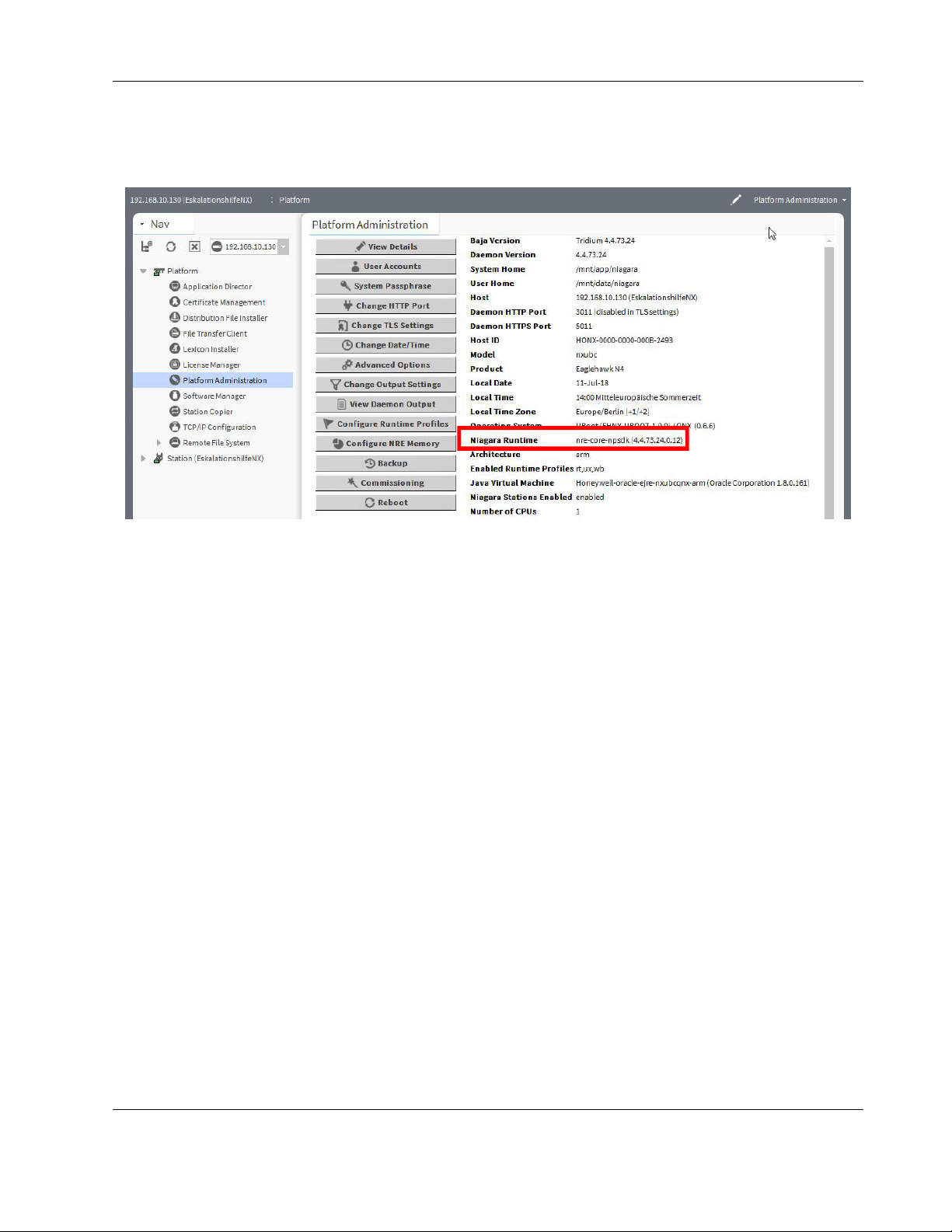
Firmware Update
1. Check the firmware version installed in your EAGLEHAWK NX as follows:
Open COACH NX, go to the Platform/Platform Administration, and check the version of the Niagara Runtime installed in the
EAGLEHAWK NX.
2. Close COACH NX.
3. Get the firmware upgrade package from the CentraLine Partnerweb. At present, this package is contained in
EAGLEHAWKNX-SupportPackage_17July2018.zip.
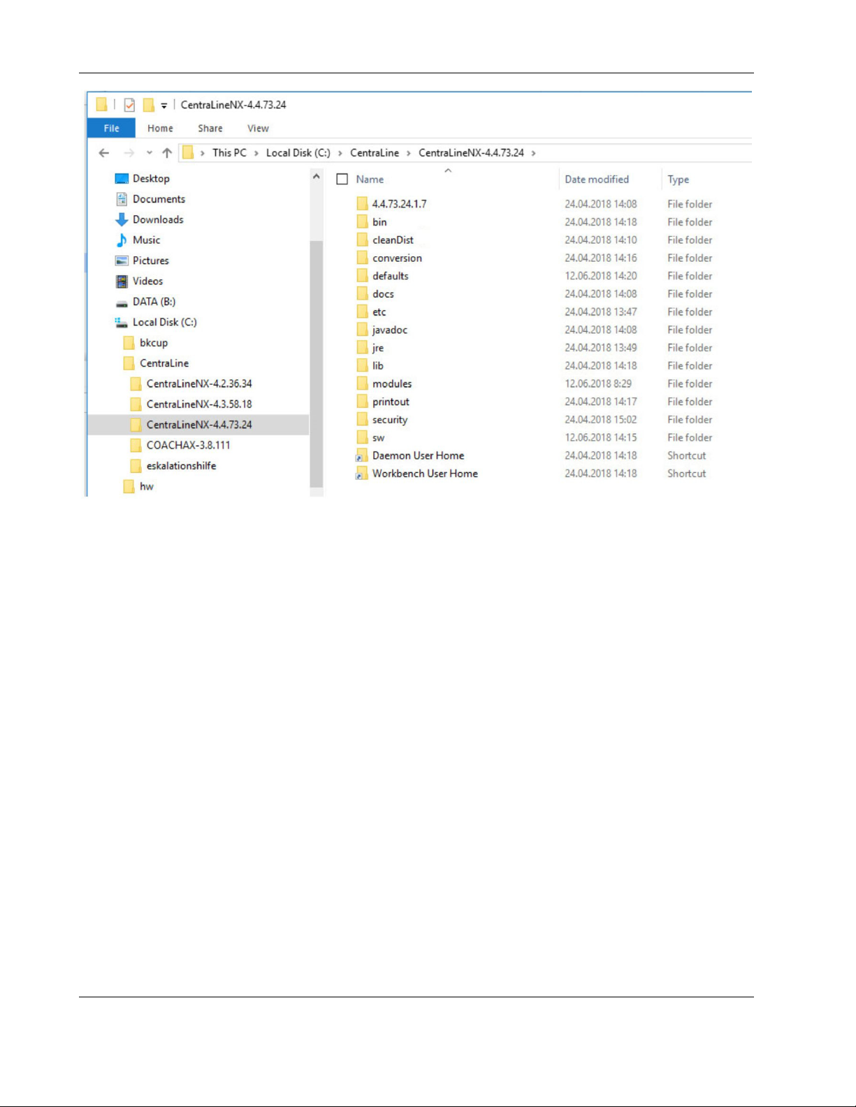
4. Navigate with Windows Explorer to your installation folder. For version NX 4.4.73.24, the default folder is
c:\CentraLine\CentraLineNX-4.4.73.24
15 EN1Z-1039GE51 R1218
EAGLEHAWK NX CONTROLLER – INSTALLATION & COMMISSIONING INSTRUCTIONS
5. Double click the “Workbench User Home” link, you will be redirected to the user home
6. Navigate to <user home>/sw/inbox folder. Resulting path for 4.4. is:
C:\Users\<your username>\Niagara4.4\tridium\sw\inbox
7. Copy and paste all four firmware files (contained in the firmware upgrade package) into the aforementioned inbox.
8. Run the platform daemon.
9. Restart COACH NX.
EN1Z-1039GE51 R1218 16
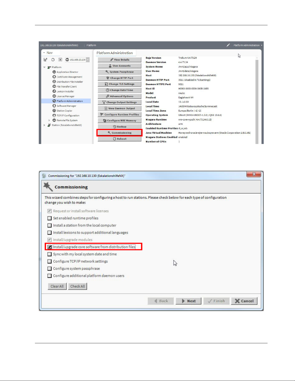
EAGLEHAWK NX CONTROLLER – INSTALLATION & COMMISSIONING INSTRUCTIONS
10. Connect to the EAGLEHAWK NX and start the Commissioning Wizard.
11. Deactivate all checkboxes; only Update Core Software needs to be selected.
12. Start the commissioning process.
17 EN1Z-1039GE51 R1218
 Loading...