

Page 1

CLIF-CBUSLC Interface
TABLE OF CONTENTS
Installation &
Commissioning
Instructions
TABLE OF CONTENTS ...........................................................1
Safety Information ..................................................................2
General Safety Information .................................................2
Information as per EN 60730 .............................................2
WEEE Directive ..................................................................2
Standards, Approvals, etc. .................................................2
Related Technical Literature .................................................2
Specifications .........................................................................3
System Overview ....................................................................3
Overview of Hardware ........................................................3
System Architecture ...........................................................4
Bus and Port Connections ..................................................5
Mounting/Dismounting ....................................................... 12
Before Installation ............................................................ 12
Dimensions ...................................................................... 12
Wiring and Set-Up ............................................................... 13
General Safety Considerations ....................................... 13
Wiring Terminals .............................................................. 13
Terminal Assignment ....................................................... 13
Power Supply ................................................................... 13
RIN-APU24 ...................................................................... 14
Lightning Protection ......................................................... 14
Engineering, Commissioning ............................................ 15
Required Preparations ..................................................... 15
Extra Parts ............................................................................ 16
LonWorks Communications ............................................... 17
General Information .......................................................... 17
Connecting to a LONWORKS Network ............................... 17
C-Bus Connection ................................................................ 18
C-Bus Topologies ............................................................. 18
C-Bus Cables ................................................................... 18
Connecting CLIF-CBUSLC via RS485-1 to C-Bus .......... 19
Effect of Poll Rate + Subscribed Points on CPU Load ..... 20
C-Bus-Related Size Recommendations .......................... 20
Troubleshooting ................................................................... 21
General ............................................................................. 21
Power LED (green) of CLIF-CBUSLC .............................. 21
Status LED (red) of CLIF-CBUSLC .................................. 21
L2 LED .............................................................................. 21
Tx and Rx LEDs ............................................................... 21
Appendix 1: Earth Grounding ............................................. 22
CLIF-CBUSLC and SELV ................................................ 22
CLIF-CBUSLC and Standard EN60204-1 ........................ 22
Earth Grounding of EN60204-1 Applicable Systems ....... 22
Index ...................................................................................... 24
Trademark Information
ONWORKS, and Neuron are trademarks of Echelon
LON, L
Corporation registered in the United States and other
countries.
® U.S. Registered Trademark
Copyright © 2017 Honeywell Inc. • All Rights Reserved EN1Z-1026GE51 R0417
Page 2
CLIF-CBUSLC INTERFACE – INSTALLATION & COMMISSIONING INSTRUCTIONS
SAFETY INFORMATION
General Safety Information
► When performing any work, all instructions given by the
manufacturer and in particular the safety instructions
provided in these Installation and Commissioning
Instructions are to be observed. Make sure that the local
standards and regulations are observed at all times.
► The CLIF-CBUSLC Interface and C-Bus controllers may be
installed and mounted only by authorized and trained
personnel.
► If the device housing is damaged or missing, immediately
disconnect it from any power.
► If the device is broken or defective, do not attempt to repair
it yourself; rather, return it to the manufacturer.
► It is recommended that devices be kept at room tem-
perature for at least 24 hours before applying power. This
is to allow any condensation resulting from low shipping /
storage temperatures to evaporate.
► The CLIF-CBUSLC must be installed in such a manner
(e.g., in a lockable cabinet) as to ensure that uncertified
persons have no access to the terminals.
► In the case of vertical mounting on DIN rails, the CLIF-
CBUSLC Interface should be secured in place using a
commercially-available stopper.
► If the CLIF-CBUSLC is modified in any way, except by the
manufacturer, all warranties concerning operation and
safety are invalidated.
► Rules regarding electrostatic discharge should be followed.
► Use only accessory equipment which comes from or has
been approved by Honeywell.
Information as per EN 60730
Purpose
The purpose of the device is: OPERATING CONTROL. The
CLIF-CBUSLC is an interface device intended for HVAC in
home (residential, commercial, and light-industrial)
environments.
Construction
The CLIF-CBUSLC is an independently mounted electronic
control unit with fixed wiring.
Mounting Method
The CLIF-CBUSLC is suitable for mounting as follows:
► in cabinets;
► in fuse boxes conforming with standard DIN43880, and
having a slot height of max. 45 mm;
► on walls (using accessory MVC-80-AC1).
Table 1. Information as per EN 60730
Shock protection
Pollution degree
Installation
Software class
Ball-pressure test
temperature
Class II
2
Class 3
Class A
housing parts >75 °C
terminals >125 °C
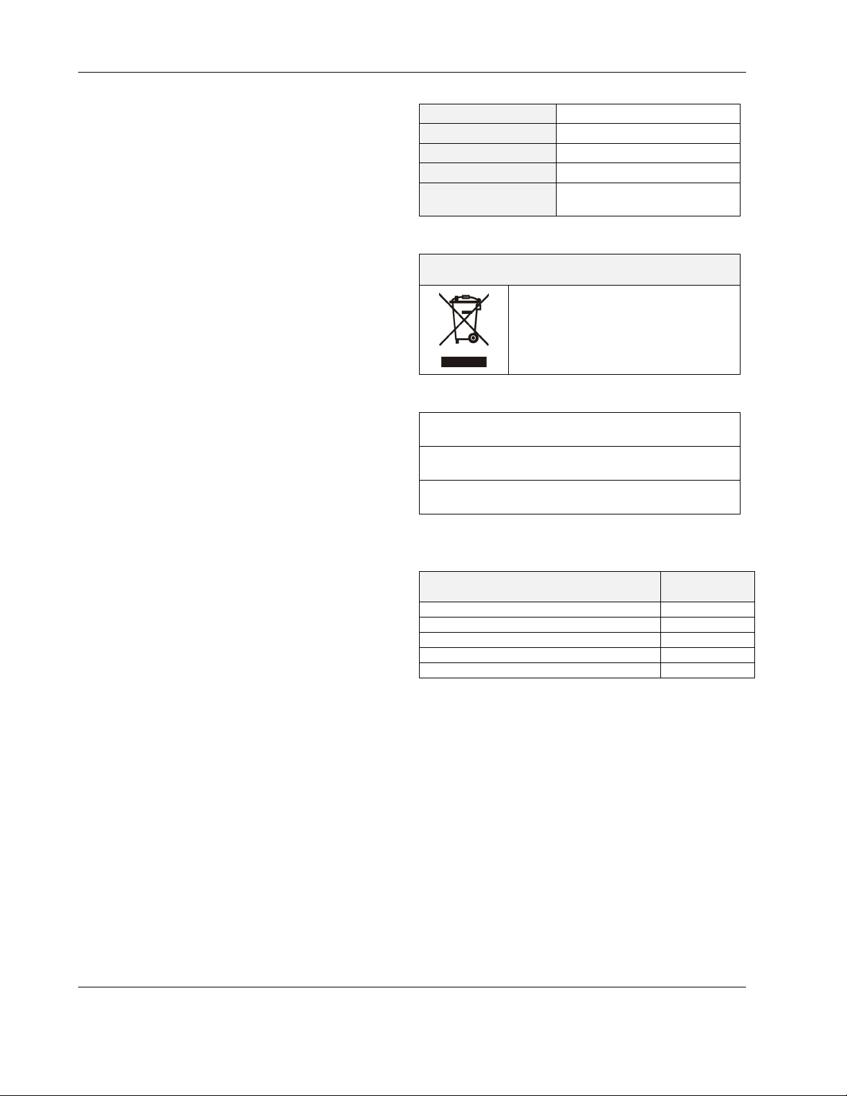
WEEE Directive
WEEE: Waste Electrical and Electronic
Equipment Directive
At the end of the product life, dispose of
the packaging and product in an
appropriate recycling center.
Do not dispose of the device with the
usual domestic refuse.
Do not burn the device.
Standards, Approvals, etc.
Degree of Protection: IP20 (mounted on walls, with two
Refer to Code of Practice standards IEC 61000-5-1 and -2
for guidance.
The device complies with Ethernet Protocol versions IEEEC
802.3.
accessory MVC-80-AC1 covers)
RELATED TECHNICAL LITERATURE
Table 2. Related Technical Literature
Title
CLIF-CBUSLC – Product Data EN0Z-1026GE51
CLIF-CBUSLC – Mounting Instructions MU1Z-1026GE51
CentraLine NX C-Bus Driver – User Guide EN2Z-1021GE51
IF-LON2 – Product Data & Mounting Instr. MU1Z-0545GE51
General Security Best Practices EN0Z-1017GE51
Product
Literature no.
EN1Z-1026GE51 R0417 2
Page 3
SPECIFICATIONS
Power supply
Power consumption
Current consumption
Ambient temperature
Storage temperature
Humidity
Dimensions
Degree of protection
Fire class
Weight
SYSTEM OVERVIEW
Overview of Hardware
CLIF-CBUSLC INTERFACE – INSTALLATION & COMMISSIONING INSTRUCTIONS
Table 3. CLIF-CBUSLC specifications
19 … 29 VAC, 50/60 Hz or
20 … 30 VDC
typically dc: 5 W; max. 6 W
typically ac: 9 VA; max. 11 VA
typically dc: 210 mA; max. 240 mA
typically ac: 370 mA; max. 410 mA
0 … 40 °C (wall-mounting)
-20 … +70 °C
5 … 95% r.h. non-condensing
See Fig. 12 and Fig. 13.
IP20 (mounted on walls, with two accessory MVC-80-AC1 covers)
V0
0.6 kg (excl. packaging)
Table 4. Overview of hardware
feature description
RS485-1, isolated, C-Bus communication 1200 m 1
bus
interfaces
LEDs
Ethernet Interface
USB 2.0 Device Interface (as Network Interface) 3 m 1
USB 2.0 Host Interface (max. 500 mA) 3 m 1
power LED (green) -- 1
status LED (red, controllable by firmware) -- 1
LED L1 (yellow) unused -- 1
LED L2 (yellow) indicating that a SUSI client (ARENAAX, COACHAX or ARENA 3.0) is connected -- 1
bus status LEDs (for isolated RS485-1 interface) -- 2
max.
cable
length
e-mail communication, browser access 100 m 1
SUSI IP communication 100 m 1
no.
3 EN1Z-1026GE51 R0417
Page 4
CLIF-CBUSLC INTERFACE – INSTALLATION & COMMISSIONING INSTRUCTIONS
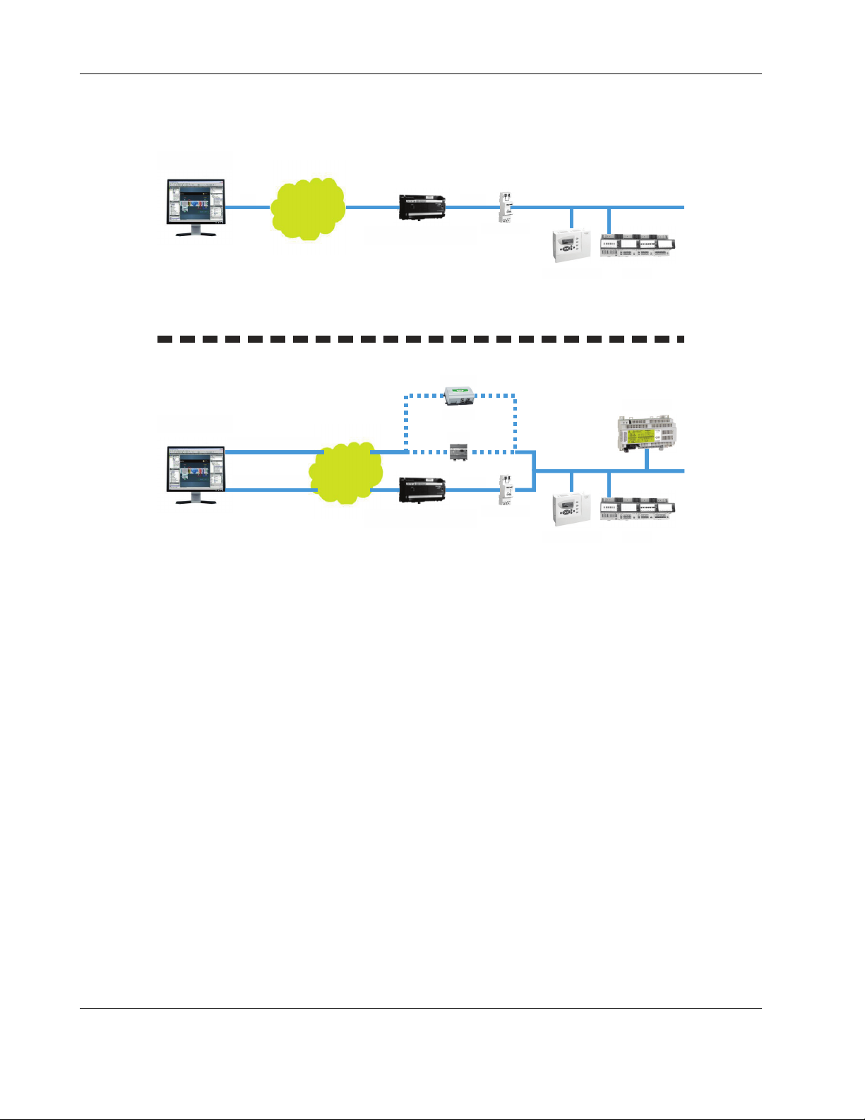
System Architecture
ARENA 3.xx
IP
IP
NETWORK
CLIF-CBUSLC
ARENA NX
LonWorks via IP
IP
C-BUS via IP
NETWORK
CLIF-CBUSLC
Fig. 1. CentraLine C-Bus System architecture
USB
HAWK
- OR -
L-IP
USB
IF-LON2
IF-LON2
PANTHER
PANTHER
LION
SERVAL
LION
EN1Z-1026GE51 R0417 4
Page 5
CLIF-CBUSLC INTERFACE – INSTALLATION & COMMISSIONING INSTRUCTIONS
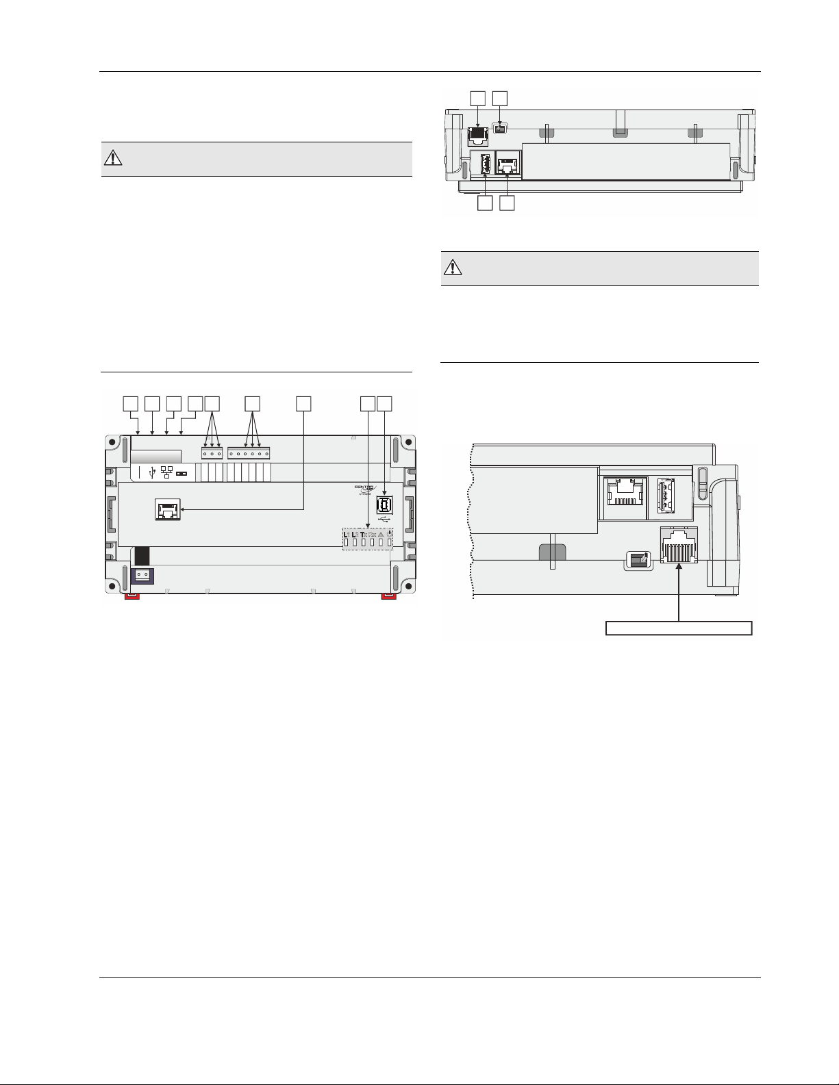
Bus and Port Connections
Overview
WARNING
Risk of electric shock or equipment damage!
► Do not touch any live parts in the cabinet!
► Disconnect the power supply before making connections
to or removing connections from terminals of the CLIFCBUSLC
► Do not reconnect the power supply until you have
completed installation.
► It is prohibited to power the CLIF-CBUSLC with the same
transformer used to power controllers or other devices
(e.g., the PW M-Bus Adapter).
► Observe the rules regarding electrostatic discharge.
5
485-1-
485-1+
6 7
n.a.
n.a.
485-2-
485-2+
9
n.a.
GND2
182
RS232
J1 J8
3
4
END
BIAS
MID
RS485-1
24 25 26 27 28 29 30 31 32
GND1
1 4
J1 J8
3
2
Fig. 3. Side view
WARNING
Risk of electric shock or equipment damage!
► It is prohibited to connect any of the RJ45 sockets of the
CLIF-CBUSLC Interface to a so-called PoE-enabled device
("Power over Ethernet").
RS232 / RJ45 Socket
Via its RS232 / RJ45 socket, the CLIF-CBUSLC can be
connected to a terminal for debugging purposes.
J1 J8
24V~
24V-0
1
2
Fig. 2. Top view
Legend
1 RS232 / RJ45 socket (for factory debugging)
2 USB 2.0 Host Interface (for connection of the IF-
LON2); max. 500 mA, high speed
3 Ethernet / RJ45 socket (for SUSI communication);
10/100 Mbit/s; 1 "link" LED and 1 "activity" LED
4 Three-position slide switch (for setting bias and ter-
mination resistance of RS485-1: MUST REMAIN IN
MIDDLE POSITION!)
5 RS485-1 (isolated; for C-Bus communication)
6 RS485-2 (non-isolated; DO NOT USE)
7 Future functionality
8 LEDs
9 USB 2.0 Device Interface (for connection to web
browser for setup)
RS232-RJ45 SOCKET
Fig. 4. RS232 / RJ45 socket
USB 2.0 Host Interface
Via its USB 2.0 Host interface, the CLIF-CBUSLC can be
connected to the IF-LON2 External Interface Adapter and thus
thus to L
also section "LonWorks Communications" on pg. 17.
ONWORKS networks. Max. 500 mA, high speed. See
5 EN1Z-1026GE51 R0417
Page 6
CLIF-CBUSLC INTERFACE – INSTALLATION & COMMISSIONING INSTRUCTIONS
USB Driver Installation
Windows 7
J1 J8
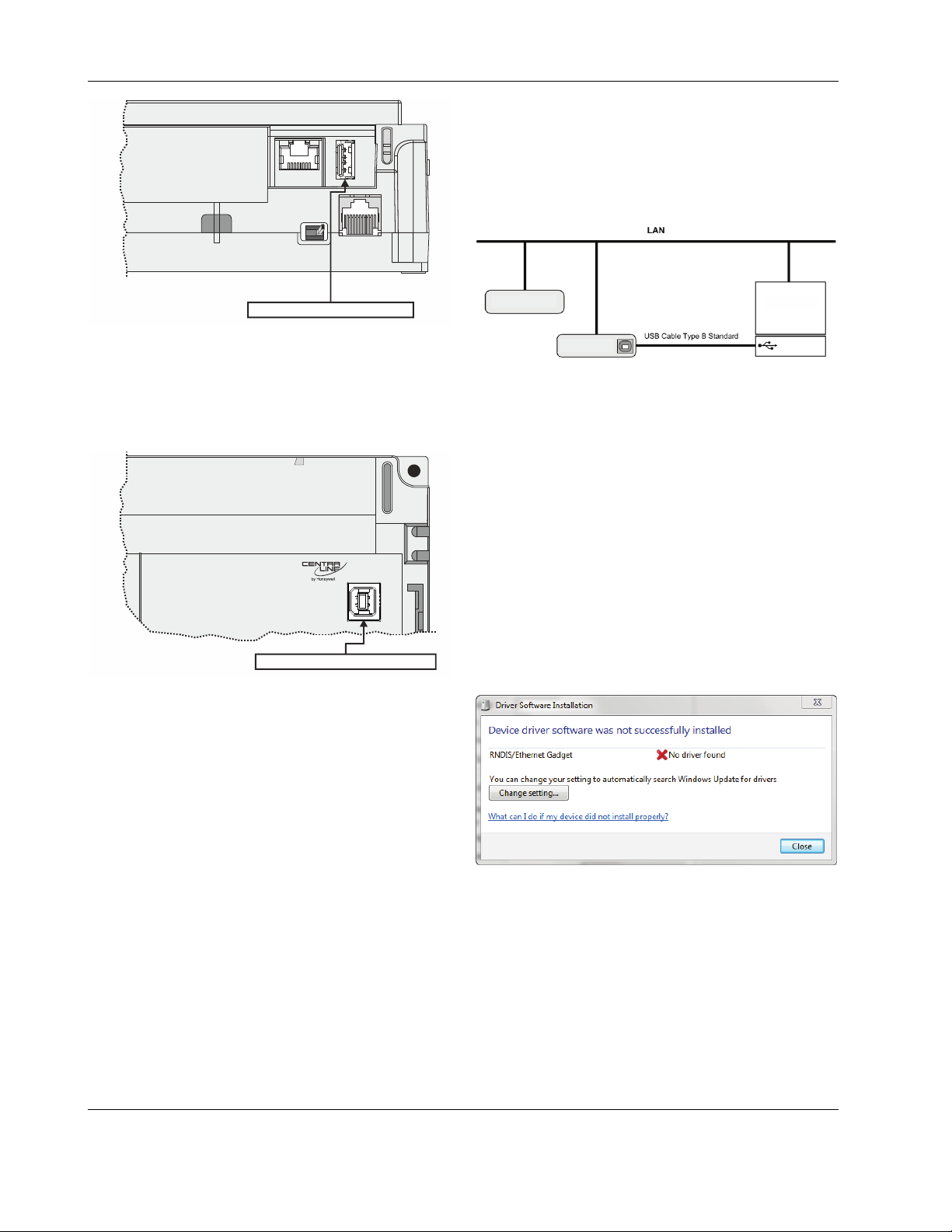
In order to connect the CLIF-CBUS Interface to the Windows
7 PC, you will need an USB cable of type A-Male-to-type-BMale (Type B standard).
The CLIF-CBUS Interface will be connected to the Windows 7
PC as shown in the following figure.
USB 2.0 Host Interface
Fig. 5. USB 2.0 Host interface
USB 2.0 Device Interface
The CLIF-CBUSLC is equipped with a USB 2.0 Device Interface at the front. This interface is for connection to a web
browser for setting up the device.
USB 2.0 Device Interface
Fig. 6. USB 2.0 Device Interface
A standard USB type-B connector can be inserted into this
USB 2.0 Device Interface.
NOTE: Before attempting to connect a web browser to the
USB 2.0 Device Interface of the CLIF-CBUSLC,
you must first install the USB Driver on your PC.
See following section "USB Driver Installation".
CLIF-CBUSLC #2
WINDOWS 7 PC
CLIF-CBUSLC #1
Driver Variants
Depending on the firmware version, there are two different
ways to install the USB driver.
1. On most PCs, the update is done automatically with the
Windows update function.
2. In the case of firmware 4.00.00 or higher, you can use
the Microsoft driver from your Windows 7 installation
(procedure then starts with step 17 of the following
Procedure).
PROCEDURE
1. Insert the A Male connector of the USB cable into an
USB inferface jack of the PC and insert the B Male connector into the controller's USB device interface jack.
RESULT: The Found New Hardware Wizard is
enabled in the Windows Task Line.
2. In the Windows Task Line, double-click the icon.
RESULT: The Driver Software Installation message
box displays.
EN1Z-1026GE51 R0417 6
3. If no RNDIS/Ethernet Gadget driver was found as
indicated by the message "X No driver found", click the
Change setting… button.
RESULT: The Device Installation Settings dialog box
displays.
Page 7
CLIF-CBUSLC INTERFACE – INSTALLATION & COMMISSIONING INSTRUCTIONS
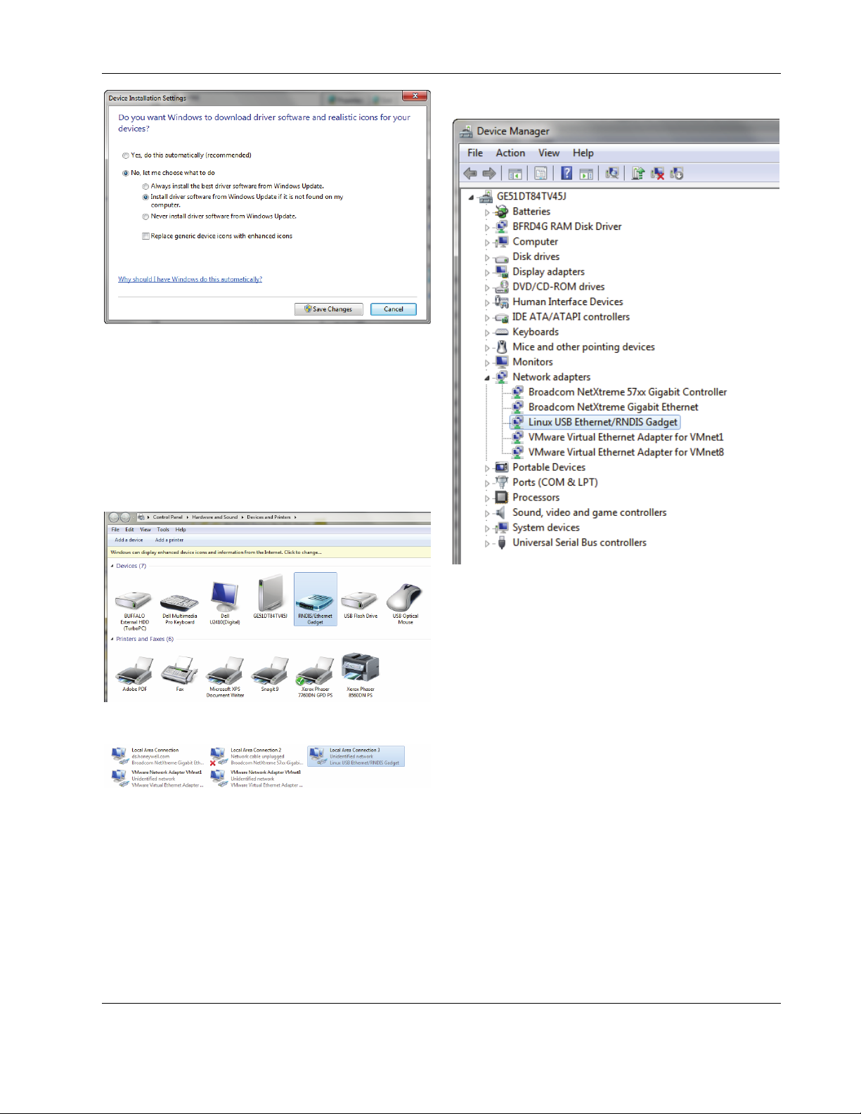
In Control Panel \ Device Manager \ Network Adapters
4. Select No, let me choose what to do, and then select
Install driver software from Windows Update if it is
not found on my computer.
5. Click the Save Changes button.
RESULT: Software tries to install the RNDIS / Ether-
net Gadget driver. If the driver is successfully installed, it can be seen in the following
locations within Windows (see figures
below):
In Control Panel \ Hardware and Sound \ Devices and Printers
In Control Panel \ Network and Internet \ Network Connections
6. If the driver has still not been successfully installed, do
the following:
7. Right-click on the driver in the Network adapters folder
in the Device Manager, and then click Update Driver
Software.
8. Click Browse my computer for driver software.
9. Click Let me Pick from a list of device drivers on my
computer.
10. Click Have Disk…
11. Click Browse… and navigate to the folder
<drive:>\CARE\drivers.
12. Depending on your Windows operating system type (32bit or 64-bit), select the RNDIS USB driver (32-bit) or the
RNDIS USB driver (64-bit) file, and then click Open.
13. Click OK.
14. Select Linux USB Ethernet/RNDIS Gadget, and then
click Next>.
15. If a warning message displays, click Continue Anyway.
RESULT: Windows will install the driver.
16. Click Close.
17. Check the successful installation of the driver as
described in step 5.
18. If this still does not work, use the driver shipped with
Windows.
19. Right-click on the driver in the Network adapters folder
in the Device Manager, and then click Update Driver
Software.
20. Click Browse my computer for driver software.
7 EN1Z-1026GE51 R0417
Page 8
CLIF-CBUSLC INTERFACE – INSTALLATION & COMMISSIONING INSTRUCTIONS
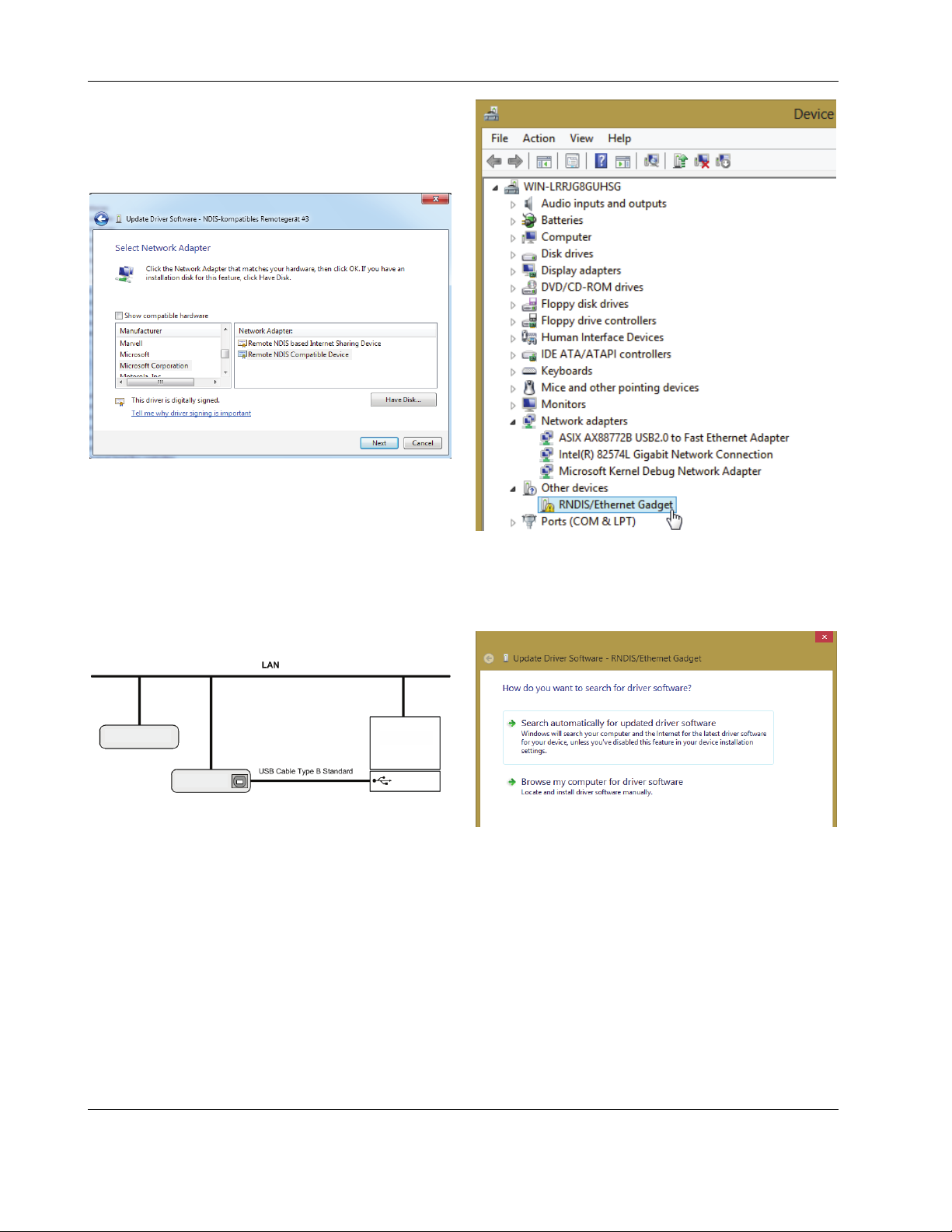
21. Click Let me Pick from a list of device drivers on my
computer.
22. Uncheck the Show compatible hardware box.
23. Select the Manufacturer Microsoft Corporation
24. Select Remote NDIS Compatible Device
25. Check the successful installation of the driver as
described in step 5.
26. If the device status is “This device cannot start. (Code
10)”, reboot your PC.
Windows 8
In order to connect the CLIF-CBUS Interface to the Windows
8 PC, you will need an USB cable of type A-Male-to-type-BMale (Type B standard).
The CLIF-CBUS Interface will be connected to the Windows 8
PC as shown in the following figure.
CLIF-CBUSLC #2
CLIF-CBUSLC #1
WINDOWS 8 PC
PROCEDURE
1. Insert the A Male connector of the USB cable into an
USB interface jack of the PC and insert the B Male
connector into the controller's USB device interface jack.
2. In Windows, start the device manager.
3. Click Other devices, then right-click RNDIS/Ethernet
Gadget and then select Update driver Software…
RESULT: The Update Driver Software – RNDIS /
Ethernet Gadget dialog displays.
4. Click Browse my computer for driver Software…
EN1Z-1026GE51 R0417 8
Page 9

CLIF-CBUSLC INTERFACE – INSTALLATION & COMMISSIONING INSTRUCTIONS
5. Click Let me pick from a list of device drivers on my
computer.
6. Select Network adapters.
8. Select USB-RNDIS-Adapter, and then click Next button.
RESULT: The Update Driver Warning message box
9. Confirm the warning by clicking Yes button.
RESULT: The driver will be installed successfully as
displays.
indicated by the final message box.
10. Click the Close button.
7. Select Microsoft.
9 EN1Z-1026GE51 R0417
Windows 10
In the case of controllers with firmware 4.00.00 or higher, the
appropriate driver is automatically installed with a Windows
update. In the case of controllers with firmware 3.04.05 or
Page 10

CLIF-CBUSLC INTERFACE – INSTALLATION & COMMISSIONING INSTRUCTIONS
lower, the automatic installation does not work: Please download the appropriate USB driver prior to the installation at:
http://catalog.update.microsoft.com/v7/site/ScopedViewRedire
ct.aspx?updateid=37e35bd4-d788-4b83-9416-f78e439f90a2
Please connect the controller to the PC as described in
section "Windows 8" and perform the general installation
procedures for drivers in Windows 10.
Ethernet / RJ45 Socket
The CLIF-CBUSLC is equipped with an Ethernet / RJ45
socket featuring one LED.
J1 J8
Ethernet / RJ45 socket
Fig. 7. Ethernet / RJ45 socket
This Ethernet / RJ45 socket is a 10/100-Mbaud Ethernet
interface permitting communication with a SUSI client like
AX
ARENA
(as per IEEEC 802.3)
NOTE: The Ethernet / RJ45 socket is usually earth-
, ARENANX, COACHAX, COACHNX, or ARENA 3.0
LINK/ACT.
Fig. 8. Ethernet / RJ45 socket
grounded. For additional information on earth
grounding, see also "Appendix 1: Earth Grounding"
on pg. 22.
LEDs
The CLIF-CBUSLC features the following LEDs:
Fig. 9. CLIF-CBUSLC LEDs
Table 5. CLIF-CBUSLC LEDs
symbol
See also section "Troubleshooting" on page 21 for a detailed
description of the behaviors of the LEDs and their meanings.
RS485 Interface
General
The CLIF-CBUSLC has one C-Bus interface:
RS485-1 (consisting of push-in terminals 24 [GND-1], 25,
RS485-1 Bias and Termination Resistors
RS485-1 is equipped with a three-position slide switch which
can be used to switch its bias resistors OFF (position "MID" –
this is the default and the only allowed setting), ON (position
"BIAS"), and ON with an additional 150Ω termination resistor
(position "END").
color function, description
L1 yellow unused
L2 yellow
LED indicating that a SUSI client
(ARENA
AX
, COACHAX or ARENA 3.0) is
connected
Tx yellow
Rx yellow
!
red status LED indicating hardware problems
RS485-1 status LED indicating transmission of C-Bus signals
RS485-1 status LED indicating reception
of C-Bus signals.
green power LED
and 26) is isolated.
J1 J8
MID
BIAS
END
EN1Z-1026GE51 R0417 10
RS485-1
3-POSITION SLIDE SWITCH
Fig. 10. RS485-1 three-position slide switch
The slide switch setting must remain in the leftmost position
for "MID".
Page 11

CLIF-CBUSLC INTERFACE – INSTALLATION & COMMISSIONING INSTRUCTIONS
Table 6. Required slide switch settings
setting remarks
END DO NOT USE!
BIAS DO NOT USE!
MID
For C-Bus communication, the switch must be in the
leftmost position.
+5V
MID
(MANDATORY!)
RS485-1 (+)
47 kOHM
ISO
25
MID
BIAS
RS485-1 (-)
END
47 kOHM
26
GND-1
Fig. 11. RS485-1 three-position slide switch setting MID
RS485 Standard
According to the RS485 standard (TIA/EIA-485: "Electrical
Characteristics of Generators and Receivers for Use in
Balanced Digital Multipoint Systems"), only one driver communicating via an RS485 interface may transmit data at a
time. Further, according to U.L. requirements, the RS485
interface may be loaded with a max. of 32 unit loads. A max.
of 29 C-Bus devices may be connected.
IMPORTANT
The cable length affects the baud rate. See Table 7.
Table 7. Baud rate vs. max. cable length for RS485
Baud rate Max. cable length (L)
9.6 - 76.8 kbps 1200 m
For information on wire gauge, max. permissible cable length,
possible shielding and grounding requirements, and the max.
number of devices which can be connected to a bus, refer to
standard EIA-485.
11 EN1Z-1026GE51 R0417
Page 12

CLIF-CBUSLC INTERFACE – INSTALLATION & COMMISSIONING INSTRUCTIONS
MOUNTING/DISMOUNTING
Before Installation
IMPORTANT
To allow the evaporation of any condensation resulting from low shipping / storage temperatures, keep the device at room
temperature for at least 24 h before applying power.
US requirement, only: This device must be installed in a UL-listed enclosure offering adequate space to maintain the
segregation of line voltage field wiring and Class 2 field wiring.
In the case of vertical mounting on DIN rails, the CLIF-CBUSLC should be secured in place using a commercially-available
stopper. See also the CLIF-CBUSLC – Mounting Instructions (MU1Z-1006GE51).
Dimensions
215.5
25 262728 29 30 31 32
24
END
BIAS
RS232
RS485-1
MID
GND1
n.a.
n.a.
485-1-
485-1+
n.a.
485-2-
485-2+
GND2
57.5
49.5
J1 J8
24V~
24V-0
1
2
5245
110
Fig. 12. CLIF-CBUSLC (shown: model with onboard I/Os), dimensions (in mm)
215.5
J1 J8
57.5
52
147
Fig. 13. CLIF-CBUSLC with covers, dimensions (in mm)
NOTE: Use of the covers (MVC-80-AC1) obstructs access to the Ethernet and USB 2.0 Host Interfaces and RS232 socket.
EN1Z-1026GE51 R0417 12
Page 13
CLIF-CBUSLC INTERFACE – INSTALLATION & COMMISSIONING INSTRUCTIONS
WIRING AND SET-UP
General Safety Considerations
All wiring must comply with applicable electrical codes and
ordinances, including VDE, National Electric Code (NEC)
or equivalent, and any local regulations must be observed.
Refer to job or manufacturer’s drawings for details. Local
wiring guidelines (e.g., IEC 364-6-61 or VDE 0100) may
take precedence over recommendations provided here.
Electrical work should be carried out by a qualified
electrician.
Electrical connections must be made at terminal blocks.
For Europe only: To comply with CE requirements, devices
with a voltage in the range of 50 ... 1000 VAC or 75 ...
1500 VDC which are not provided with a supply cord and
plug or with other means for disconnection from the supply
having a contact separation of at least 3 mm in all poles
must have the means for disconnection incorporated in the
fixed wiring.
WARNING
Risk of electric shock or equipment damage!
► Observe precautions for handling electrostatic sensitive
devices.
► Do not touch any live parts in the cabinet.
► Do not open the device housing.
► Disconnect the power supply before making connections to
or removing connections from terminals of the CLIFCBUSLC and devices wired to it.
► Do not use spare terminals as wiring support points.
► To prevent risk of injury due to electrical shock and/or
damage to the device due to short-circuiting, low-voltage
and high-voltage lines must be kept separate from one
another.
► All terminals are protected (up to 24 Vac) against short-
circuiting and incorrect wiring. Higher voltages may
damage the device.
► Do not reconnect the power supply until you have
completed the installation.
Fusing Specifications
System Fusing
We recommend that the system be equipped with an external
fuse.
Fusing of Active Field Devices
F2 (depends upon given load).
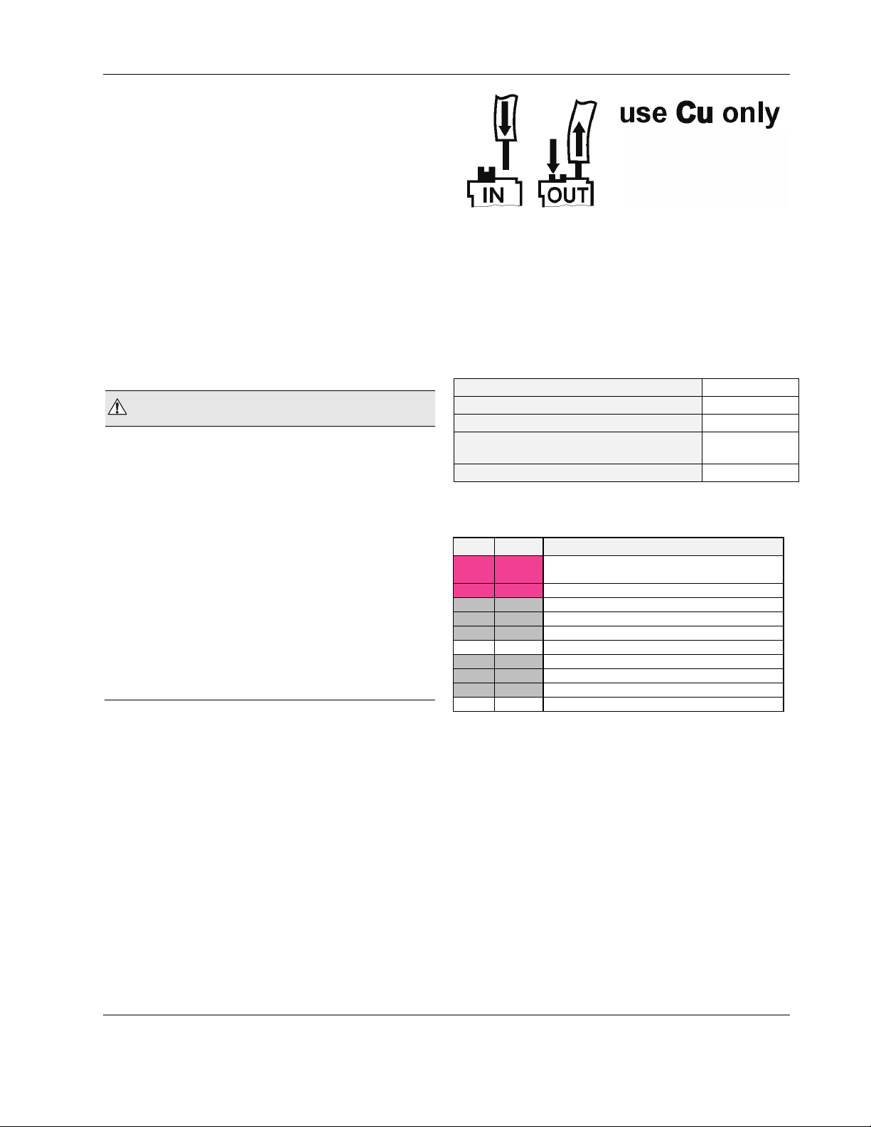
Wiring Terminals
The CLIF-CBUSLC is equipped with push-in terminal plugs.
Fig. 14. Inserting/removing wires from push-in terminals
NOTE: With solid conductors, ferrules are prohibited.
NOTE: Use only one conductor per push-in terminal.
NOTE: If, nevertheless, two stranded wires are to be
plug gauge
solid conductor H05(07) V-K
stranded conductor H05(07) V-K
stranded conductor with wire end ferrules
(w/o plastic collar)
stripping length
connected to a single push-in terminal, twin wire
end ferrules must be used.
Table 8. CLIF-CBUSLC push-in terminal wiring
specifications
0.2 … 1.50 mm
0.2 … 1.50 mm
0.2 … 1.50 mm
0.2 … 1.50 mm
10.0 +1.0 mm
Terminal Assignment
Table 9. Terminal assignment
term. signal description
1 24V-0
2 24V~ supply voltage (24V)
24 GND-1 reference GND of RS485-1 (isolated)
25 485-1+ "+" signal for RS485-1 (isolated)
26 485-1- "-" signal for RS485-1 (isolated)
27,28 not used
29 485-2+ not used
30 485-2- not used
31 GND-2 not used
32 - not used
supply voltage (GND), internally connected
with terminal 31
Power Supply
Powering CLIF-CBUSLC
Power is supplied via a removable terminal plug (attached to
terminals 1 and 2).
The power supply of the CLIF-CBUSLC must conform to
Safety Class II. To reduce overall current consumption, the
CLIF-CBUSLC can be powered by a switch power supply
(rather than by a transformer). See also Table 3 on pg. 3.
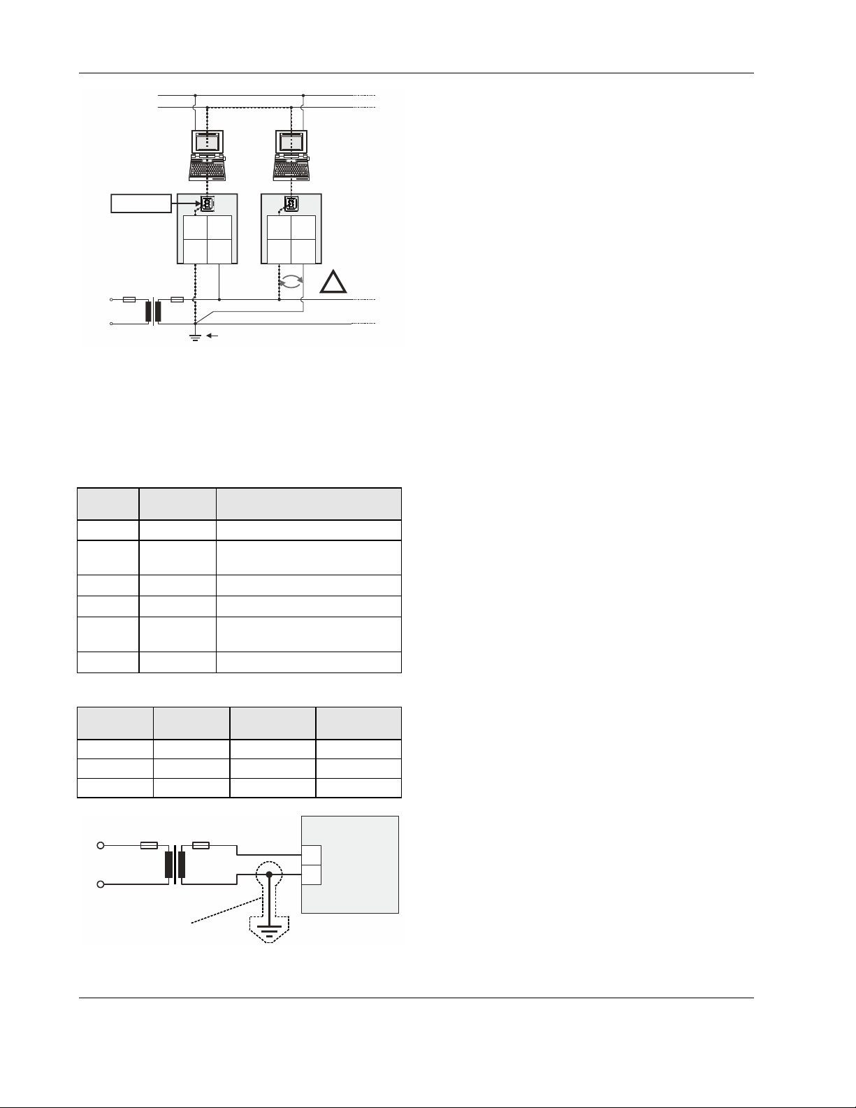
NOTE: Danger of short-circuiting when another controller
besides the CLIF-CBUSLC is supplied by the same
transformer if proper polarity is not ensured. See
Fig. 15.
2
2
2
2
13 EN1Z-1026GE51 R0417
Page 14
CLIF-CBUSLC INTERFACE – INSTALLATION & COMMISSIONING INSTRUCTIONS
EARTH GROUND
N, L
SHORT-CIRCUITING!
PC 1 PC 2
USB 2.0
Device Interface
CPU #1 CPU #2
L
LINE
N
24 V~
24 V~0
24V~ 24V~24V~0 24V~0
2 21 1
NOISE-FREE EARTH GROUND
(ONLY ONE PER SYSTEM)
CPU 2
REVERSED
!
POLARITY!
Fig. 15. Incorrect polarity → SHORT-CIRCUITING!
Transformer Data
In Europe, if the CLIF-CBUSLC is powered by transformers,
then such transformers must be safety isolating transformers
conforming to IEC61558-2-6. In the U.S. and Canada, if the
CLIF-CBUSLC is powered by transformers, then such transformers must be NEC Class-2 transformers.
Table 10. 1450 series transformers data
part #
1450 7287
-001 120 Vac 24 Vac, 50 VA
-002 120 Vac
-003 120 Vac 24 Vac, 100 VA, 24 Vdc, 600 mA
-004 240/220 Vac 24 Vac, 50 VA
-005 240/220 Vac
-006 240/220 Vac 24 Vac, 100 VA, 24 Vdc, 600 mA
transformer primary side
CRT 2 230 Vac 2 A 500 mA
CRT 6 230 Vac 6 A 1300 mA
CRT 12 230 Vac 12 A 2500 mA
primary side secondary side
2 x 24 Vac, 40 VA, 100 VA from
separate transformer
2 x 24 Vac, 40 VA, 100 VA from
separate transformer
Table 11. Overview of CRT Series AC/DC current
max. AC
current
PRIMARY SIDE
max. DC
current
CLIF-CBUSLC
RIN-APU24
The RIN-APU24 Uninterruptable Power Supply can be directly
wired to a CLIF-CBUSLC.
See RIN-APU24 Uninterruptable Power Supply – Mounting
Instructions (Product Literature no.: EN0B-0382GE51) for a
detailed wiring diagram.
Lightning Protection
Please contact your local Honeywell representative for
information on lightning protection.
230 VAC
120 VAC
24 VAC
24 V0
2
1
NOT
RECOMMENDED
Fig. 16. Connection of CLIF-CBUSLC
EN1Z-1026GE51 R0417 14
Page 15
CLIF-CBUSLC INTERFACE – INSTALLATION & COMMISSIONING INSTRUCTIONS
ENGINEERING, COMMISSIONING
Please refer also to ARENAAX / COACHAX – User Guide
(Product Literature No.: EN2Z-0996GE51) for detailed
information.
Required Preparations
In order to access (with a laptop or PC) the CLIF-CBUSLC via
Ethernet/IP for the first time, a password must be defined. For
setup, you must connect a PC with a web browser to the USB
2.0 Device interface as described below.
USB 2.0 Device Interface
This USB 2.0 Device interface is the interface for setting up
the communication settings and downloading new firmware.
An "A-Male to B-Male" USB cable is required.
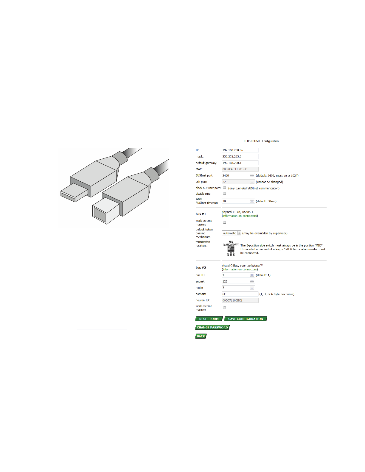
6. The configuration mask (see Fig. 18) will then appear.
Enter the IP address, subnet mask, and default gateway
address.
Do not select "block SUSInet port" (this is needed only if
you want to tunnel SUSInet communication over ssh)
7. In case you are using the virtual C-Bus over L
option, enter the L
(subnet, node, domain). You can retreive this information
from the engineering tool. Use the same subnet and
domain and a node address which is not used by another
device).
8. If you want your interface to hourly synchronize the time of
your bus devices, select "work as time master".
9. Press "SAVE CONFIGURATION". When you are done,
you may log out or go back to the status display.
ONWORKS communication parameters
ONWORKS
Fig. 17. A-male to B-male USB cable
For access via USB, the CLIF-CBUSLC has a permanent
default IP address 192.168.255.241.
Set-Up
After removing the CLIF-CBUSLC from its shipping box,
attach power and wait approx. 1 minute while it powers up.
During power-up, the red warning LED (see Fig. 9 on pg. 10)
will be lit. As soon as this warning LED goes dark, you may
commence with the set-up, as follows:
1. Connect one end of the A-male to B-male USB cable (see
Fig. 17) to your PC and the other end to the USB 2.0
Device Interface (see Fig. 6 on pg. 6) located on the front
of your CLIF-CBUSLC.
2. Enter URL http://192.168.255.241 in your web browser. An
initial mask will then appear on the screen of your PC.
3. When setting up your CLIF-CBUSLC for the first time, you
will have to enter an administrator password. This
administrator password must contain:
▪ 8 or more (but not more than 31) characters
▪ uppercase letters
▪ lowercase letters
▪ numerals
▪ no whitespace characters
4. A login mask will appear. You may now login using the
administrator password.
5. Press the CONFIGURATION button.
Fig. 18. Configuration mask
NOTE: Regarding time master functionality, the CLIF-
CBUSLC does not observe daylight saving time.
If your controllers do automatic daylight saving
time, we recommend not to use the time master
functionality. If there is a local workstation permanently on the bus, we recommend that this
workstation should be responsible to synchronize
date and time.
15 EN1Z-1026GE51 R0417
Page 16
CLIF-CBUSLC INTERFACE – INSTALLATION & COMMISSIONING INSTRUCTIONS
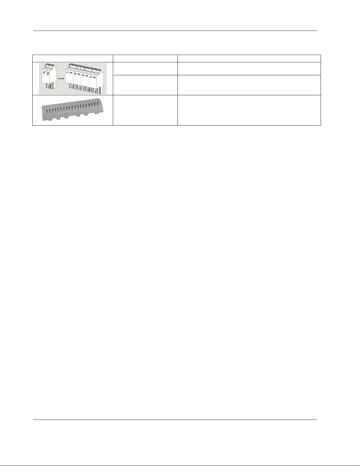
EXTRA PARTS
Table 12. Extra parts
TPU-11-01
TPU-45-01
order no. description
Removable terminal plugs, push-in type; complete set of 3
plugs (for terminals 1 - 47); for the CLAXEH00ND100A.
Removable terminal plugs, push-in type; complete set of 9
plugs (for terminals 1 - 47); for the CLAXEH14ND100A and
CLAXEH26ND100A.
MVC-80-AC1
Terminal cover (color: RAL9011); package of ten.
EN1Z-1026GE51 R0417 16
Page 17
CLIF-CBUSLC INTERFACE – INSTALLATION & COMMISSIONING INSTRUCTIONS
LONWORKS COMMUNICATIONS
General Information
The CLIF-CBUSLC can be connected to LONWORKS networks.
networks. This requires the use of an IF-LON2 (see section
"IF-LON2" below), which is then plugged into to the CLIFCBUSLC's USB 2.0 Host Interface (see also section "USB 2.0
Host Interface" on pg. 5).
This permits individual CLIF-CBUSLC Interfaces to be
connected / disconnected from the L
without disturbing the operation of other devices.
The L
ONWORKS network is insensitive to polarity, eliminating
the possibility of installation errors due to miswiring.
Different network configurations (daisy-chain, loop, and star
configurations, or any combination thereof) are possible. See
also Excel 50/500 L
ONWORKS Mechanisms Interface
Description (Product Literature no.: EN0B-0270GE51).
Connecting to a LONWORKS Network
IMPORTANT
Do not bundle wires carrying field device signals or
ONWORKS communications together with high-voltage
L
power supply or relay cables. Specifically, maintain a
min. separation of 3 inches (76 mm) between such
cables. Local wiring codes may take precedence over
this recommendation.
IMPORTANT
Try to avoid installing in areas of high electromagnetic
noise (EMI).
Cable Types
The unit must be wired to the LONWORKS network using either
level IV 22 AWG (Belden part number 9D220150)
or
plenum-rated level IV 22 AWG (Belden part number
9H2201504) non-shielded, twisted-pair, solid-conductor
wire.
When possible, use Honeywell AK3781, AK3782, AK3791, or
AK3792 cable (US part numbers). See Excel 50/5000
L
ONWORKS Mechanisms (Product Literature no.: EN0B-
0270GE51), for details, including maximum lengths.
Use wire with a minimum size of 20 AWG (0.5 mm
maximum size of 14 AWG (2.5 mm
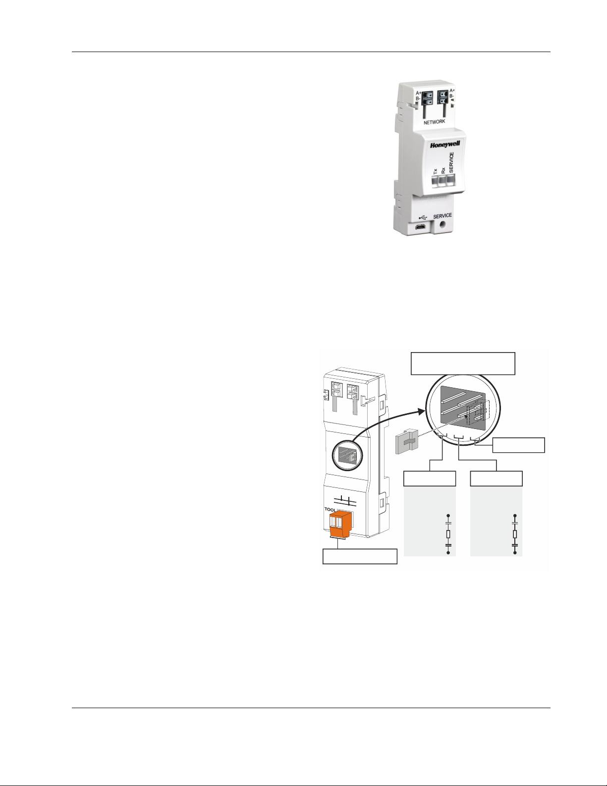
IF-LON2
Optionally, communication with physical I/O modules, with
room and zone controllers, and with CentraLine PANTHER,
TIGER, and LION controllers can utilize LonTalk.
The IF-LON2 is equipped with a free-topology transceiver
(FTT10A) for communication (at a data transmission rate of
78 Kbaud) on L
protocol).
The L
ONWORKS network is insensitive to polarity, eliminating
the possibility of installation errors due to miswiring. Different
network configurations (daisy-chain, loop, and star configurations, or any combination thereof) are possible. See
Excel 50/5000 L
no.: EN0B-0270GE51) for details.
ONWORKS® networks (using the LonTalk
ONWORKS Mechanisms (Product Literature
ONWORKS network
2
).
2
) and a
Fig. 19. IF-LON2
See also IF-LON2 – Mounting Instructions (Product Literature
no.: MU1B-0545GE51).
Depending upon the chosen network configuration, one or two
terminations may be required.
The following L
L
ONWORKS connection / termination module
ONWORKS termination module is available:
(mountable on DIN rails and in fuse boxes),
order no.: XAL-Term2
LONWORKS TERMINATION
PLUG-IN JUMPER
1
REMOVABLE SCREW-TYPE
2-POLE TERMINAL BLOCK
Fig. 20. L
5
2
6
PAR K P OS ITIO N
(NO TERMINATION)
FTT/LPT BUS FTT/LPT FREE
3
4
1
5
2
6
3
4
ONWORKS connection and termination module
FTT/LPT
BUS TOPOLOGY:
105 OHM
100 μ
105 Ohm
100 μ
1
2
FTT/LPT
FREE TOPOLOGY:
52.3 OHM
100 μ
52.3 Ohm
100 μ
1
2
17 EN1Z-1026GE51 R0417
Page 18
CLIF-CBUSLC INTERFACE – INSTALLATION & COMMISSIONING INSTRUCTIONS
C-BUS CONNECTION
The CLIF-CBUSLC features an RS485 interfaces to which C-Bus devices can be connected: RS485-1 (consisting of push-in
terminals 24 [GND-1], 25, and 26).
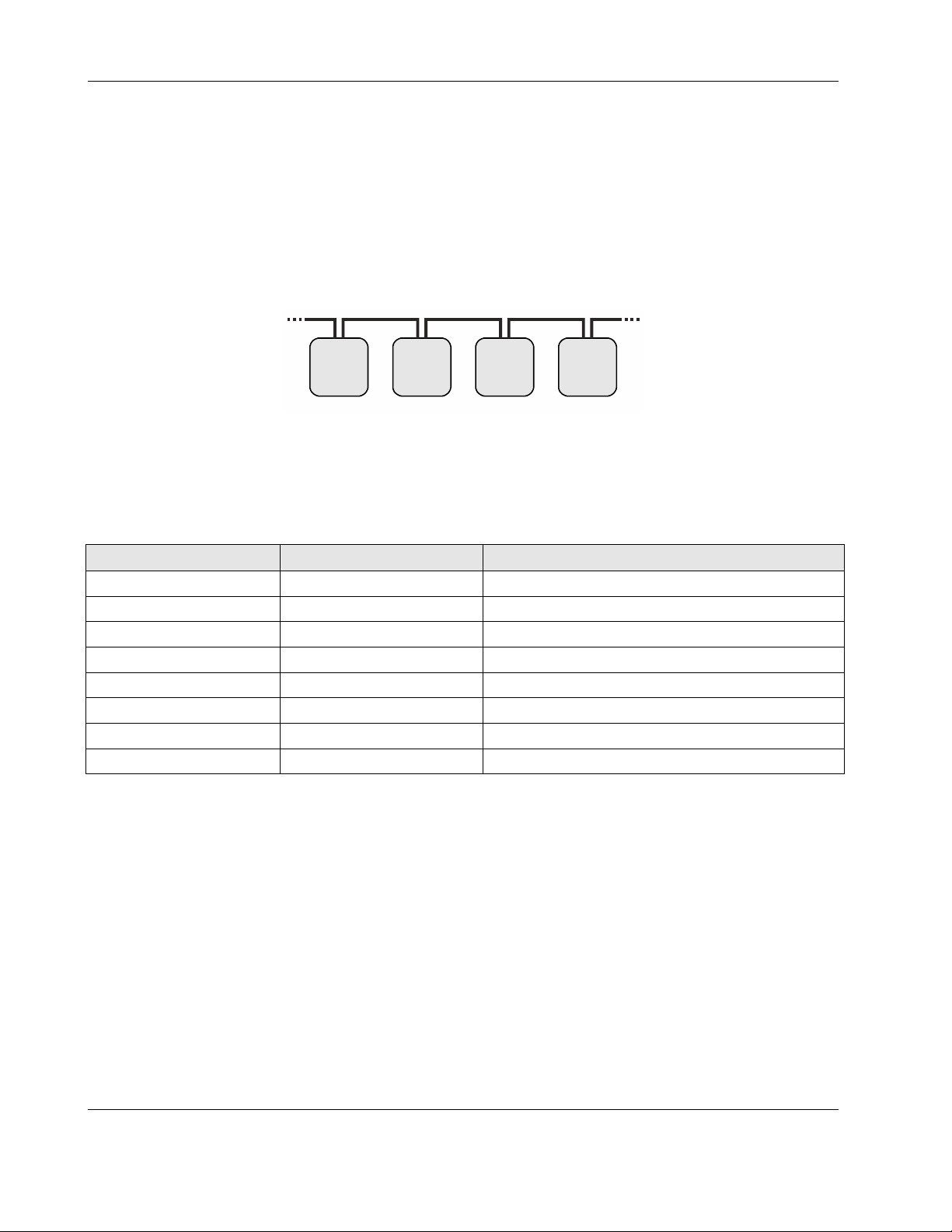
C-Bus Topologies
Via the C-Bus, up to 30 C-Bus devices (e.g., controllers, etc.) can communicate with one another and a PC central. The C-Bus
must be connected via the individual controllers (open ring).
NOTE: Star connection is not allowed, as this might cause uncontrollable line reflections.
Instead of CLIF-CBUSLC Interfaces, C-Bus controllers (e.g., the Excel 500, Excel 100, LION, PANTHER) can also be
connected.
CLIF-
CBUSLC
Excel 100 Excel 500
Fig. 21. C-Bus topology Excel 5000
PANTHER
C-Bus Cables
NOTE: Observe national regulations for C-Bus cables!
Cable type Description Recommended for
J-Y-(ST)Y 2 x 2 x 0.8 shielded, twisted pair Europe, inside cabinet
A-Y-(ST)Y 2 x 2 x 0.8 shielded, twisted pair Europe, outside cabinet
AK 3702 unshielded, twisted pair US not approved for Europe
AK 3740A shielded US (low-cost) not approved for Europe
Belden 9842 twisted pair Europe, US also possible
Belden 9841 shielded US
AK 3702 unshielded, twisted pair US not approved for Europe
AK 3740A shielded US (low-cost) not approved for Europe
For Europe; only shielded cable is permitted.
For the U.S., shielded or unshielded cable can be used.
Table 13. C-Bus cable types
EN1Z-1026GE51 R0417 18
Page 19

CLIF-CBUSLC INTERFACE – INSTALLATION & COMMISSIONING INSTRUCTIONS
Connecting CLIF-CBUSLC via RS485-1 to C-Bus
NOTE: Always power each CLIF-CBUSLC and the connected C-Bus devices via separate transformers.
NOTE: The max. C-Bus cable length is 1200 m (4000 ft).
NOTE: If any devices are not electrically isolated, signal ground connection is recommended. See section "RS485 Standard"
NOTE: If the CLIF-CBUSLC is connected at either of the line's two ends, an additional termination resistor (RT = 120 Ohm) is
NOTE: Regardless of the position of the CLIF-CBUSLC along the C-Bus, the 3-position switch must be set to MID.
Example: CLIF-CBUSLC and Connected C-Bus Devices
on pg. 11.
necessary.
NOTE!
R
T
120 OHM
24 25 26
GND-1
ISO
+5V
47 kOHM 47 kOHM
RS485-1 (+) RS485-1 (-)
CLIF-CBUSLC
= C-BUS DEVICE #1
24V~
24~0
1 2
F1
24 V
230 V
L
RS485-1
MID
GND-1
RS485 -
RS485 +
C-BUS
DEVICE #2
GND
RS485 +
C-BUS
DEVICE #3
RS485 -
GND
GND
RS485 -
RS485 +
C-BUS
DEVICE #N-1
NOTE!
END
MID
BIAS
Fig. 22. Connection of a CLIF-CBUSLC via its RS485-1 interface to a C-Bus
RS485 -
RS485 +
C-BUS
DEVICE #N
GND
19 EN1Z-1026GE51 R0417
Page 20

CLIF-CBUSLC INTERFACE – INSTALLATION & COMMISSIONING INSTRUCTIONS
EFFECT OF POLL RATE + SUBSCRIBED POINTS ON CPU LOAD
The poll rate set for the CLIF-CBUSLC and the chosen number of subscribed datapoints both make a demand on the CPU load.
The following recommendations are therefore applicable.
C-Bus-Related Size Recommendations
Table 14. Recommended application sizes per controller and per project
No. of controllers
No. of datapoints
No. of datapoints per
project
No. of I/O modules per
LION controller
No. of time programs per
controller
Table 15. Recommended limits for CLIF-CBUSLC and C-Bus communication
Virtual C-Bus (i.e.,
C-Bus via LONWORKS)
Physical C-Bus systems
* This corresponds mainly to the no. of datapoints in trend if these datapoints do not update faster than once per minute. In the
case of physical C-Bus systems, the update rate of each datapoint can be influenced by the user (i.e., by changing the attribute
"trend hysteresis").
Operating System: WIN xx 32-bit Operating System: WIN xx 64-bit
9…13 LION controllers 15…17 LION controllers
15…17 PANTHER / TIGER controllers 15…17 PANTHER / TIGER controllers
Max. 381 per LION controller Max. 381 per LION controller
Max. 381 per PANTHER / TIGER controller Max. 381 per PANTHER / TIGER controller
4953 5715
Max. 16 (We recommend using only Panel Bus
I/O modules since they do not count as
ONWORKS devices.)
L
As many 25 I/O modules (combination of Panel
Bus I/O modules and L
are possible, but with some risk.
up to ≤ 64
local sys.
remote sys.
9,600 bps
76,800 bps
ONWORKS I/O modules)
No. of C-Bus devices
engineered with…
COACH CARE
15 29 10,000 10,000 500
15 29 10,000 10,000 250
15 29 10,000 -- 500
15 29 10,000 -- 1,000
Max. 16 (We recommend using only Panel Bus
I/O modules since they do not count as
L
ONWORKS devices.)
As many 25 I/O modules (combination of Panel
Bus I/O modules and L
are possible, but with some risk.
Max. 64
As many as 100 time programs per controller are
possible, but with some risk.
No. of data-
points
ONWORKS I/O modules)
No. of NVs
Update rate (data-
points per min.)*
EN1Z-1026GE51 R0417 20
Page 21

CLIF-CBUSLC INTERFACE – INSTALLATION & COMMISSIONING INSTRUCTIONS
TROUBLESHOOTING
General
The following LEDs of the CLIF-CBUSLC can be used for troubleshooting purposes:
Power LED (green)
Status LED (red)
L2 LED (yellow)
Tx (sending data on RS485-1) and Rx (receiving data on RS485-1) LED
Power LED (green) of CLIF-CBUSLC
Table 16. CLIF-CBUSLC power LED
case power LED meaning remedy
ON Normal operation No action necessary.
1
OFF
2
Status LED (red) of CLIF-CBUSLC
case status LED meaning remedy
OFF after
1
power-up
ON con-
2
tinuously after
power-up
L2 LED
case bus LEDs meaning remedy
1
ON
continuously
after power-up
2
Dark
Tx and Rx LEDs
case bus LEDs meaning remedy
1
Both Tx and Rx
are flashing
2
Both Tx and Rx
are OFF
3
Rx is flashing
and Tx is OFF
4
Tx is flashing
and Rx is OFF
Power supply not OK.
Table 17. CLIF-CBUSLC status LED
Normal operation. No action necessary.
– No or invalid firmware
Table 18. CLIF-CBUSLC L2 LED
AX
A SUSI client (ARENA
ARENA 3.0) is connected
No client is connected
Normal operation; RS485-1 is functioning
properly.
No communication on RS485-1.
Communication on RS485-1 has been
switched OFF, but the CLIF-CBUSLC is
receiving data from controllers.
The CLIF-CBUSLC is attempting to establish
communication on RS485-1, but there is no
answer.
, COACHAX or
Table 19. CLIF-CBUSLC Tx and Rx LEDs
► Check power supply voltage.
► Check wiring.
► If problem persists, replace hardware.
► Try powering down and then powering up the CLIF-
CBUSLC.
► If problem persists, replace hardware.
No action necessary.
► If you are unable to establish communication, check
IP address, SUSI port number, …
No action necessary
► Switch ON communication on RS485-1. Further
handling like case 4 (below).
► Use client to establish a connection with correct
device ID and baud rate
► The communication rate (Kbaud) on RS485-1 has
not been correctly set; controllers on the C-Bus may
have been setup incorrectly; wiring problem or
hardware defect.
21 EN1Z-1026GE51 R0417
Page 22

CLIF-CBUSLC INTERFACE – INSTALLATION & COMMISSIONING INSTRUCTIONS
APPENDIX 1: EARTH GROUNDING
CLIF-CBUSLC and SELV
In order to avoid distribution of noise or earth ground potential
differences over networks or other connections, the CLIFCBUSLC is designed to be in compliance with SELV (Safety
Extra-Low Voltage).
Furthermore, SELV offers the greatest possible safety against
electrical impact.
To support SELV, all Honeywell external (CRT series) or
internal transformers comply with standard EN60742.
Earth grounding is therefore not recommended.
CLIF-CBUSLC and Standard EN60204-1
However, if compliance with EN60204-1 is required, note the
following:
General Information about EN60204-1
EN60204-1 defines electrical safety for a complete application
/ machine including controllers, sensors, actuators and any
connected/controlled electrical device.
EN60204-1 requires controllers to be powered by PELV
(Protective Extra-Low Voltage) and earth grounding of the
secondary side of the used transformers or earth grounding of
the system ground.
Earth grounding is prescribed to prevent unexpected start-up
of connected rotating/moving machines due to an insulation
fault and double earth grounding somewhere in the plant.
In order to fulfill PELV (if earth grounding is prohibited), the
use of an earth leakage monitor is also possible.
When is EN60204-1 Applicable to CLIF-CBUSLC
Systems?
Safety against electrical impact
– EN60204-1 is not mandatory; this is because electrical
safety is provided by the use of SELV and transformers
according to standard EN60742.
Safety against unexpected start-up of rotating/moving
machines
– If the application/plant does not contain machines that
can be harmful to the operator due to an unexpected
start-up, the standard EN60204-1 is not applicable.
If such machines are encountered, then EN60204-1 must be
followed. Grounding is required.
Earth Grounding of EN60204-1 Applicable
Systems
NOTE: Our recommendation is that each CPU be supplied
► If system protective earth grounding is planned, use a
► For connection details, refer to the following examples.
Example 1
The following explains how to connect and earth multiple
CPUs (e.g., multiple CLIF-CBUSLCs, PANTHERs, TIGERs,
LIONs, etc. or any combination thereof) earth-grounded as
per EN60204-1.
NOTE: Use a noise-free earth ground inside the cabinet.
NOTE: If a field device that prohibits earth grounding is
► Connect earth ground to the respective terminal of the
L
LINE
N
L
LINE
N
(RECOMMENDED USE OF SEPARATE TRANSFORMERS)
with electricity from its own dedicated transformer.
cable as short as possible for grounding:
min. 1.5 mm² (16 AWG).
connected to the system ground, an isolation
monitoring device must be used instead of earth
grounding.
CPU, see Fig. 24.
CPU 1
RS485-2 + RS485-2 -
24V~24V~0
29 30
21
24 V~
24 V~0
NOISE-FREE EARTH GROUND
(ONLY ONE PER SYSTEM)
CPU 2
RS485-2 + RS485-2 -
24V~24V~0
29 30
21
24 V~
24 V~0
NOISE-FREE EARTH GROUND
(ONLY ONE PER SYSTEM)
Fig. 23. Connecting and earthing multiple CPUs
I/O MODULE I/O MODULE
COM
COM
24V~ 24V~24V~0 24V~0
B
A
74 7472 7273 7371 71
COM
COM
B
A
RECOMMENDED
24 V~
Y
GND
FIELD DEVICE
EN1Z-1026GE51 R0417 22
Page 23

CLIF-CBUSLC INTERFACE – INSTALLATION & COMMISSIONING INSTRUCTIONS
Example 2
When connecting multiple CPUs to a single transformer, it is
imperative that the polarity of the power supply terminals of
the CPUs and the polarity of the transformer always correspond (namely: 24V-0 of the transformer must always be
connected to 24V-0 of the CPU, and 24V~ of the transformer
must always be connected with 24V~ of the CPU).
Depending upon the individual CPU, the numbering of the
corresponding two terminals may possibly deviate from the
norm (which is usually "terminal 1 = 24V-0" and "terminal 2 =
24V~"). In the following example, CPU 3 has a deviating
numbering and must be connected accordingly.
NOTE: When using a single transformer for several CPUs,
NOTE: If the field device transformer is physically far away
NOTE: Use one star-point to split power for multiple CPUs
► Connect earth ground to the proper terminal of the CPU.
each CPU ground must wired separately to the
star-point.
from the CPUs, earth grounding must still be
performed for the controller.
and field devices.
DEVIATING
CPU 1 CPU 2 CPU 3 CPU N
24V~ 24V~ 24V~ 24V~24V~0 24V~0 24V ~0 24V~ 0
2 2 2 21 1 1 1
NUMBERING!
LINE
24 V~
24 V~0
NOISE-FREE EARTH GROUND
(ONLY ONE PER SYSTEM)
L
N
Fig. 24. Connecting and earthing multiple CPUs
24 V~
Y
GND
FIELD DEVICE
23 EN1Z-1026GE51 R0417
Page 24

CLIF-CBUSLC INTERFACE – INSTALLATION & COMMISSIONING INSTRUCTIONS
INDEX
C-Bus
C-Bus via Ethernet Interface, 3
C-Bus via RS485-1, 5
LED, 10
C-Bus architecture, 4
C-Bus via RS485-1, 3, 10
disposal
WEEE Directive 2002/96/EC, 2
Ethernet / RJ45 socket
details, 10
protocol version, 2
Ethernet Interface
RJ45 socket, 5
External HMI
power consumption, 3
RJ45 socket, 12
extra parts
TPU-11-01 removable push-in terminal plugs, 13
TPU-45-01 removable push-in terminal plugs, 13
fusing, 13
LEDs, 5
L2, 3, 10, 21
power LED, 3, 10, 21
Rx, 3, 10, 21
status LED, 3, 10, 21
Tx, 3, 10, 21
power supply
failure indication, 21
power supply (field devices)
via Panel Bus I/O module, 14
RS232 / RJ45 socket, 5
RS232 Interface
RJ45 socket, 5
safety
electrical safety as per EN60204-1, 22
general safety information, 2, 13
PELV, 22
SELV, 22
USB
USB 2.0 Device Interface, 3, 5
details, 6
initially accessing CLIF-CBUSLC via Ethernet/IP, 15
USB 2.0 Host Interface, 3, 5
details, 5
Manufactured for and on behalf of the Environmental & Energy Solutions Division of Honeywell Technologies Sàrl, Rolle, Z.A. La Pièce 16, Switzerland by its Authorized Representative:
CentraLine
Honeywell GmbH
Böblinger Strasse 17
71101 Schönaich, Germany
Phone +49 (0) 7031 637 845
Fax +49 (0) 7031 637 740
info@centraline.com
www.centraline.com
Subject to change without notice
EN1Z-1026GE51 R0417
 Loading...