

Page 1
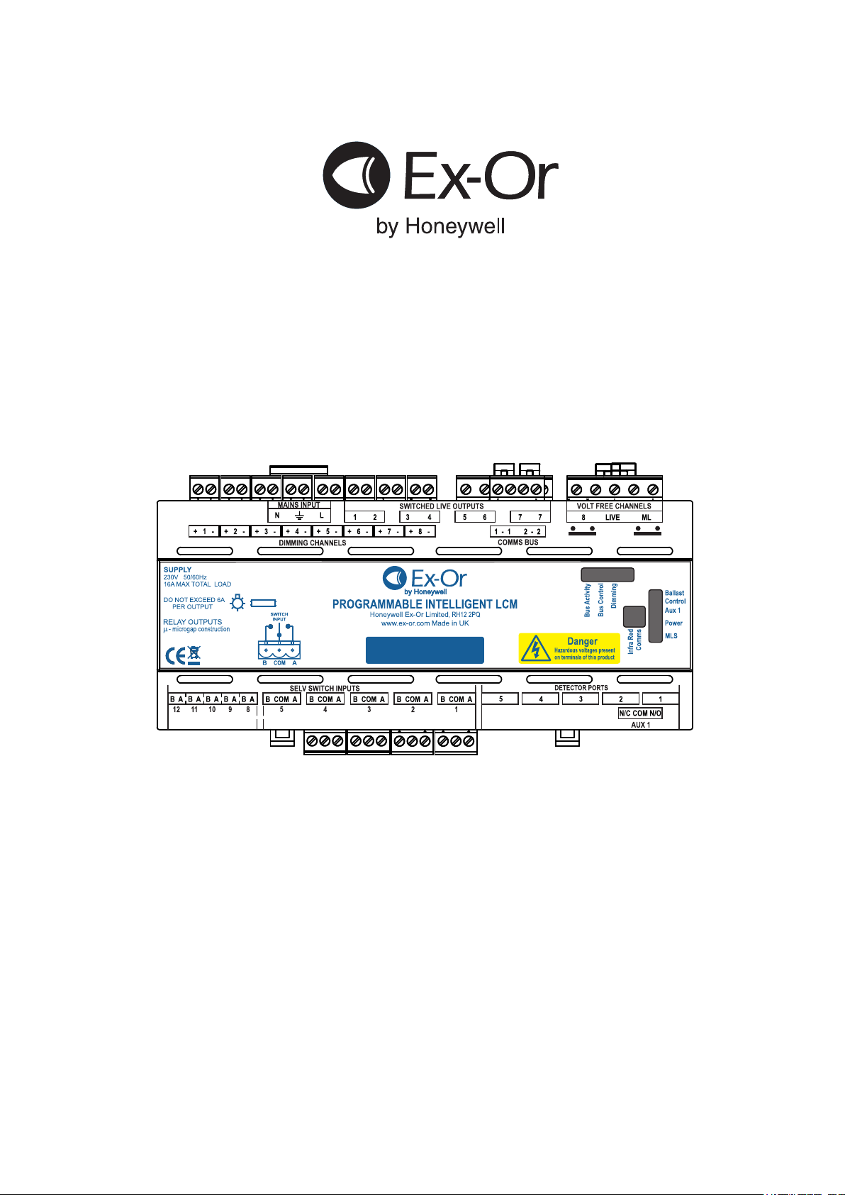
CDH8U5
8-Channel Programmable
Intelligent Lighting Control Module
Product option shown here for illustrative purposes only
Installation and Commissioning Instructions
Page 2
Introduction
The CDH8U5 is an intelligent LCM providing connections for multiple
luminaires*, up to 5 presence detectors and up to 10 SELV inputs. Provision
is made for 7 switched live outputs plus one volt-free power output. The unit
features a switched output for Maintained Live to allow initiation of
Emergency Lighting Test. In addition, the unit is provided with a volt-free
signalling output to provide control of / interface to other equipment. The
CDH8U5 is designed to simplify installation whilst providing an intelligent
managed lighting system.
Please note that during the installation after the unit is power up and no
detector has been connected (or commissioning has not been done), lights
will be on for 20min and will turn themselves off. Please also note that when
using a MLS2000SSPmk2 with the MLS Network and connecting the lights
directly to the plate instead of to the LCM the command from the RB2000 will
be ignored as it does not get through the CD box.
*Note: Refer to the Technical Data section for the maximum allowable number
of luminaires.
Fixing
The CDH8U5 should be mounted in an enclosure with a DIN-rail.
L
Loads on Channel 1
Ballast
Dimming
Ballast
Dimming
E
L
N
D
D
E
L
N
D
D
E E
N N
Note: some connectors omitted for clarity
Note: + and - relevant for
analogue versions only.
As shown above, one or more luminaires may be connected to each channel
of the CDH8U5.
Note: For the maximum number of allowable ballasts, refer to Technical
Data section.
Consideration should be given to access for installation and maintenance
when selecting the enclosure and location. The external enclosure DIN-rail
should comply with EN 60715.
Electrical Connections
The connections to this equipment should be made only by a suitably
qualified person and in accordance with the current wiring regulations.
A means of disconnection must be incorporated in the fixed mains
wiring to this box in accordance with the current wiring regulations.
All the connections should be routed ensuring adequate strain relief on the
cable before termination to the unit’s pluggable connectors.
CAUTION: DO NOT CONNECT MAINS TO THE MLS BUS OR DIMMING
OUTPUTS.
2
N
E
L
MAINS INPUT
N
3
4
DIMMING CHANNELS
1
L
5
6
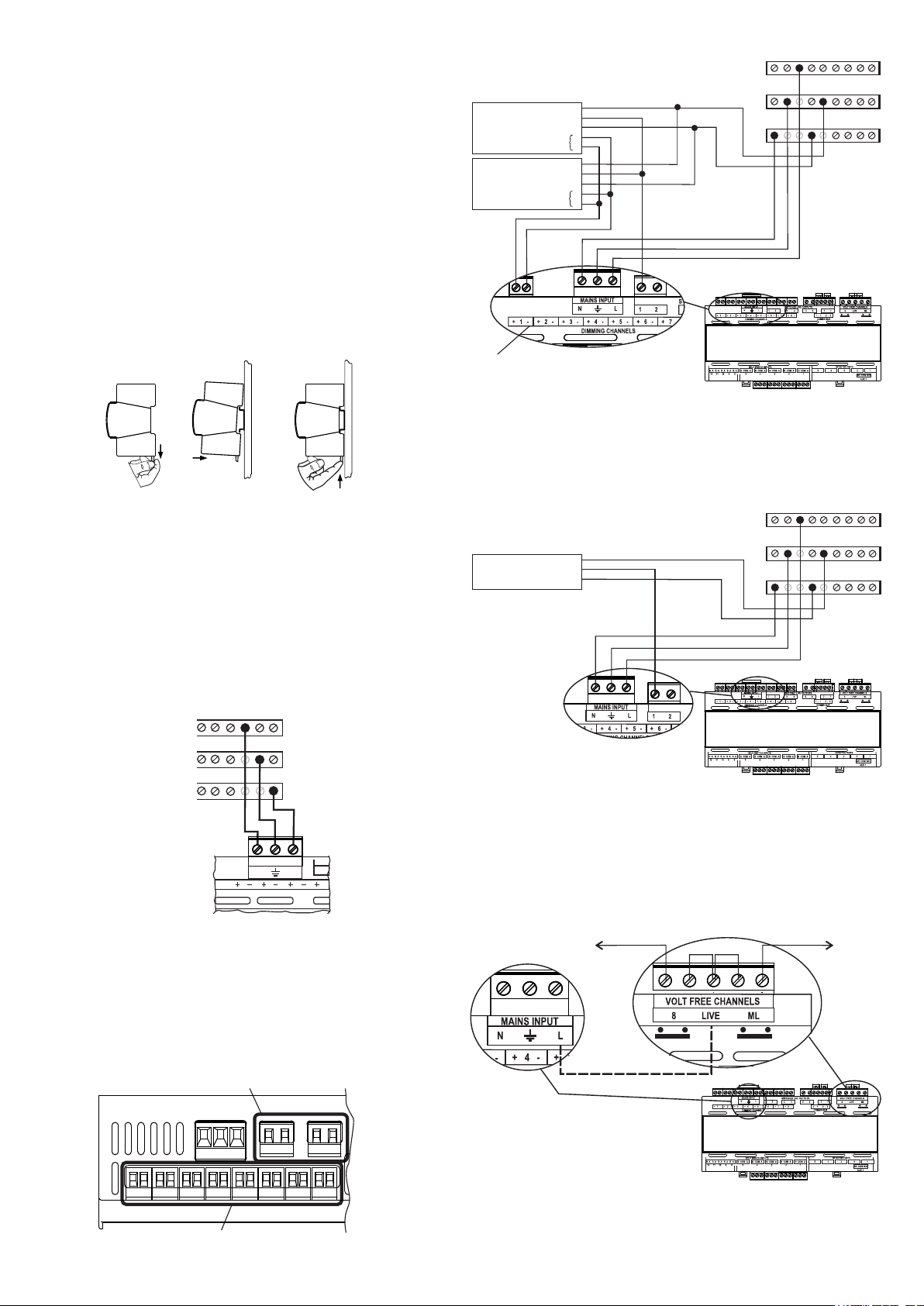
Connecting the Luminaires
Variants of the CDH8U5 are provided to control DSI (available on
configuration only), DALI and 1-10V ballasts. (See Part Numbers section for
more details.)
Note: Dimming Ballast types CANNOT BE MIXED on a single CDH8U5.
The CDH8U5 is equipped with 8 two-wire pluggable terminals for (Blue)
dimming outputs and 4 two-wire pluggable terminals are provided for (Black)
switched live outputs. Switched Live Outputs 1 through 6 are grouped in pairs
on a single plug to add mechanical strength for plugging/unplugging.
Switched Live Output 7 has two terminals for connecting the load.
(Black)
Connecting Switched Live Output
Ballast
E
L
N
L
E E
N N
Note: some connectors omitted for clarity
The CDH8U5 has 7 switched live outputs. As shown in the diagram, the
Neutral and Earth connections should be taken directly to the load.
Each Switched Live output is rated for a load of up to 6A, with a total maximum
switched live load not exceeding 16A for the unit.
Output 8 is provided as a volt-free style for extra flexibility.
Connecting Volt Free and Maintained Live Output
External shorting Links
Switched Live
Maintained
Output
Internal Link
(Blue)
Note: Earth and Neutral are connected directly to the luminaire and not
routed through the CDH8U5.
The CDH8U5 provides a 5-way terminal block for connecting mains rated Volt
Free load and Maintained Live output. For wiring convenience, the middle
terminal of the 5-way block is internally linked to the Mains Live input as
shown.
-2-
Page 3
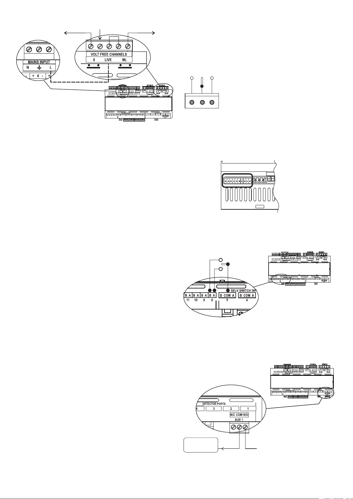
Live in from
same Phase
Switched Live
Internal Link
The diagram above shows Maintained Live generated from the internal link of
the mains supplied to the unit. Alternatively, the external shorting link can be
removed and an external supply (from the same phase) can be connected to
create a Maintained Output.
Connecting Presence Detectors
The following SELV detectors are designed to interface to the CDH8U5:
MLS2500CDR Corner-mount Microwave presence detector with
photocell, semi-flush mounted. Available with surface
mount (SM suffix).
MLS2401CDR 360° Microwave presence detector with photocell, flush
mounted. Available in surface mount version (SM
suffix).
MLS3000CDRF 360° PIR presence detector with photocell, flush
mounted. Available in surface mount version (SM
suffix).
MLS3003CDRF 360° PIR presence detector with photocell and tilting
lens, flush mounted. Available in surface mount
version (SM suffix).
MLS3003CDRMBF Mid-Bay 360° PIR presence detector with photocell and
tilting lens, flush mounted. Available in surface mount
version (SM suffix).
MLS3003CDRHBF Hi-Bay 360° PIR presence detector with photocell and
tilting lens, flush mounted. Available in surface mount
version (SM suffix).
MLSM2002CDR Controller for a 360° PIR detector with photocell. Used
with the DHS OR DHW mini-head to form an integral
luminaire-mounted unit.
Each connects to the CDH8U5 by means of an Ethernet-style RJ45
connector terminated patch lead which are available ready-made in 3m, 5m
and 10m lengths. Up to five detectors may be connected to a CDH8U5.
External
shorting
Links
Maintained
Output
Connecting Switches
The CDH8U5 is equipped with SELV switch inputs which will typically be two
way, centre off, momentary rockers,(e.g. the MK K4900 range). The logical
function of a switch can be configured from a wide range of options and its
action can be associated with any combination of channels. The switch
connection consists of a 3-pole pluggable terminal block comprising a common
and two returns from normally open contacts. Six plugs are provided with each
CDH8U5. The plug type is common with the Aux output channel. Additional
plugs can be ordered using the code CDHIP (5 pieces per pack).
Note that if the SELV status of any one of the switches
is compromised by reason of inadequate insulation or
segregation of the cabling, then the SELV status of all
other switches AND OF THE DETECTORS will also
be compromised.
A
Com
B
The recommended cable for use with the SELV switches is 3-core 3183Y
Stranded PVC Mains Power Cable H05VV-F, 0.75 mm² CSA 6 A 100m, 300 V,
500 V. The maximum allowable cable length between the switch mechanism
and the CDH8U5 terminal block is 100m.
Three separate single wires should not be used.
Connecting Switches with High Density Connector
The CDH8U5 also has provision to connect 5 additional SELV switch inputs in
order to meet the requirement of additional inputs. Unlike the 3-pole connector,
this provides two terminals A&B for each of the 5 inputs. The high density input
plug (not supplied) can be ordered using the code CDHHDIP.
Note: For the switches on the High Density Connector (SW 8-12) use any of the
‘C’ common connectors from switches 1-5.
Wiring for HD SELV Input:
Positioning Presence Detectors
For information on installing and positioning detectors, please refer to the
installation instructions provided with the particular detector.
For HD switches 8-12, use any of the ‘COM’ connections from switch inputs 1-5.
Connecting SELV Output, Aux 1
The CDH8U5 has a single SELV change-over output for signalling purposes
only. This can be used to signal an external system e.g. BMS. Connection is
made via a 3-pole pluggable terminal block (supplied) of the same type used for
SELV inputs 1-5 (CDHIP).
External BMS
Signal In
Note: The external voltage connected to Aux 1 must never exceed 24V
AC/DC. The SELV Output must be used only for signalling purposes.
Maximum current shall not exceed 1A.
24V AC/DC
-3-
Page 4

Easy integration of lighting and AV systems
The AVINTCDR provides an interface between MLS Connect Digital
Intelligent Lighting Control Module (i.e. CDW12U5-B, CDH4U5-B or
CDH8U5-B) or from any Audio Visual system that uses Dynet commands
via RS232 or RS485.
When the Ex-Or interface receives a command from the AV system, the
decoded signal is then sent to the CD Box where it is translated (a
command can recall scenes 1 to 6 of a zone in the range 1 to 100) and can
be forwarded on to the MLS Digital Network if connected to it.
The AVINTCDR allows the AV system to adjust lighting and recall lighting
scenes and behaviors via the Ex-Or MLS Digital Network System. In this
way, initiating a projector presentation, for example, would automatically
adjust the lighting to a suitable scene without needing any separate action
to dim the lights.
The MLS Connect Digital Lighting Control Module provides a gateway to
the wider MLS system but connecting directly to a CDW12U5, CDH4U5 or
CDH8U5 LCM also allows use in non-MLS applications.
Easy touch screen control of AV and lighting
User interface panels or touch screens from the Ex-Or Scene Select II
range can also be used.
Connecting to the MLS Digital Network
It is imperative that the MLS Bus be wired in the correct type of cable.
Normally
it should be Two-core multi-stranded twisted pair Cross-sectional area
1.5mm2 unscreened 600/1000V rated LSOH insulated. Please see
AN4001 from our website to learn further details on the MLS Digital
Network regarding cable needs as it differs according to different designs.
This can make your installation easier.
A MLS Digital Network will need a specific power supply. We offer this MLS
Digital Network power supply integrated in the Model CDH8U5-RB and its
variants CDH8U5-RBA and CDH8U5-RBDALI. Alternatively you can use
the
Rb2000, RB2000LT plus variants on the CDH4U5.
Do not connect Mains to the MLS Bus.
In In
Out Out
MLS Bus 1 MLS Bus 2
For connection of Bus Power Supply variants, see also Application Note
AN4030 from our website.
-4-
Page 5

Commissioning
PARAMETERS OPTIONS (Defaults, where applicable, shown in bold)
Per Box Parameter s:
Switches 1 A-5B & 6A-7B (RF1 & 2): Mo de Use r may choose any option for Switch A or Switch B (see s ection at end of table for detail s of SELV switch op tions ).
SELV Sw itc h Options Description
Sustai n Imitates m ove ment see n, as a resu lt output of Chann el remain s ON till the ass igned sw itch with 'SUSTAIN' is active.
Brighten Rais es the light level. Works on ly wi th dim mable ba llasts .
Dim Lowers th e light level. Works only with dim mable ba llasts .
Off Turns la mp OFF.
Scene 1-6 Recall s Scene as signe d (any Scene 1 to 6 as con figured).
On Turns la mp ON.
Partition Initiates logical partitio n of a room .
OneSwitch
The LCM is commissioned using a dedicated programme running on a Windows-based computer. Commissioning settings may then be directly uploaded from the computer to the
LCM or transferred to a QuickSet Pro hand-held programmer for easy upload on site. Communication from the PC can be by means of a USB infrared transceiver which can signal
directly to the LCM’s on-board infrared port over a short range or via any attached presence detector from beneath (range: 1-3m). The main parameters for configuration are tabulated
below. These parameters may be re-programmed any number of times and all settings will be retained in the event of a power loss.
Detector 1-5: Rang e (On & Off Sens itivi ty) Max: 100%, 75% or 50 % / High: 100%, 75% or 50 % / Med: 100%, 75% or 50% / Low: 100 %, 75% or 50% / Min: 100 % or 75%
Detector 1-5: Sens itivity Fine
Com mon: Address
Com mon: Switch Map
Com mon: LED Inhibi t
Com mon: Inhibit DALI Init
Com mon: Missi ng Detector
Com mon: Slow Dim (mins)
Com mon: Bus Abse nt All On
Per Channel Parameters:
Assig ned Detectors Detector 1 - Detector 5 Assi gned or Not Assig ned to this Chan nel.
Pcell Source
Assig ned Switches Switch 1A - Switch 5B & Switch 6A - 7B (RF) Ass igned or Not Assi gned to this chan nel.
Power Up
Occ Trigger Mode
Low Lux Level (Auto Abs ence)
Sw Auto Detect
Manual I/P
Occupied Scen e
Alt. Occ. Scene A & B
Start Lamps
Occupied Tim er
Photocell
Bright Out
Set-Point Low / High
Scene 2-6
Transi tion Scene
Transi tion Timer
Backgroun d Level Off
Alt. Ba ckground Scene A & B
Backgroun d Tmr
Fade to Off
Bus Co nnect
Zones 1-4
Zones 1-4 TRX
Corrido r 1-2: Begin / End
Corrido r Scene
Global 1-2 Rx
Ballas t
Lam p Max
Burn-In Hrs
Quick Burn-In
Burn-In Dim ming
Offset Dimm ing None (--) to 10 0% in 10% increm ents. Allows selected chan nels to be config ured to be b righter than a reference ch annel accordi ng to chosen 'output weightings'
Mode A, Mode B or Mode C - Applies when Sen sitivity is set to Max and during occup ancy only (Mode A = Normal, B & C = More Sensitive )
0-127 - MLS address for DALI Emergency test. D efault = 0
Normal / Direct / D irect 2 / Zero Off Dly / Modes 04 -07 (for future use) - Pre-set switch mappi ngs (except Zero Off D ly - instant off option)
Yes / No - Enab les or disab les the detector’s LEDs.
Yes / No - Preven ts the DALI b allasts from b eing initial ised every time the b ox powers up.
Normal / On Fu ll - Puts all outputs on if there’s a detector assigned to a channel and that detector isn’t present.
0-254 - Fade tim e setting, for use wi th Slow Dim an d Slow Brighten switch functions. De fault = 0
Yes / No - All li ghts default to ON in the event of a bus failu re.
None (--), 1,2,3,4,5 - Photoce ll 1-5 (in Detectors 1-5) Assign ed or Not Assigned to this chann el.
On / Off
Presence / Abse nce / Manual
0-254 (0 = feature disabled) - Used in m anual mo des: When it is dark , li ghts respond to move ment autom atically without requirin g swi tch press.
Yes / No - Used in manual modes: If set to Yes, presence detection is autom atic until a switch press is detected.
Local / Share (Local = Obey loca lly only; Share = Obey lo cally and trasmi t comm and on MLS bus)
Scene 1-6 Scene1
Scene 1-6 or -- (feature disa ble d) - Determine s different actions on entry depen dent on time of day.
Max / Min
10 se conds to 96 hou rs, Disab led. 20 mins
Regul ate (100%, 90% , 80%, 70%, 60%, 50% ) / Pas sive / Active / Disabl ed
Yes / No
Photocell Lower and Uppe r Th reshold s: 0-1023 (us ed in Regul ating Scene 1). Low = 350; High = 450
Output 0-100% or -- (no cha nge) Scene 2 = 80%; 3 = 4 0%; 4 = 20%; 5 = 10%; 6 = 5%
Scene 1-6 or -- (feature disa ble d) - Scene interpose d between 'Occ Timer' & 'Backgro und Level' to allow mo vement to restore lights at existing level.
10 se conds to 96 hou rs - Determin es length of transition scene . 10 secs
Minimum , 2 5% or Scene 6 (these options sho w XTN suffix) for 3 x Occu pied Timer, then Off.
Minimum , 2 5% or Scene 6, 5, 4, 3 or 2 (these optio ns show BLD suffix) until th e building has been vacated.
Minimum , 2 5% or Scene 6, 5, 4, 3 or 2 (Backg round Timer pa rameter appl ies to these options which have no suffix).
Scene 1-6 or -- (no scene) - Determ ines different actions when the area is vacant depe ndent on time of day.
10 se conds to 96 hou rs or -- (none ) - Applies to 'Alt Exit Scenes' and som e 'Backg round Level' scene s (i.e. not XTN and BLD option s). Whe n Backgroun d Time r
expires, chan nel's output turns off.
Yes / No
Yes / No
None (--), Zone number 1-10 0 / C ommo n 1,2,3
Tx Rx / Tx Only / Rx Only - Determines ho w z one param eters 1-4 beh ave with respect to bu s commands.
None (--), Zone number 1-10 0 / Bl d
Scene 1-6 or -- (no scene) - Movement within an are a's Corridor Begin/End span will cause th at area to go to the chosen scene. Direct mo vement within zo nes 1-4
will override th is and the channel will go to its Entry Scene.
Yes / No
1% DSI, 3% DSI, 10% DSI, 1% DALI, 3% DALI, 10% DALI (N on-Dimm ing - use defau lt i.e. 1 % DSI)
100%, 90%, 80%, 70%, 50%, 45%, 40%, 35% , 30%, 25%, 20%, 15% , 1 0%
Burn-in 10 0 hrs / Cancel / Res ume (See Appli cation Note AN4028 - limi ted functionality via Quick Set Pro )
Yes / No - If set to Yes, output rema ins on until 100-h r bu rn-in is compl eted.
Yes / No - If set to Yes, allows tempo rary (30 secs) dimm ing in response to m anual inpu ts, eve n though in 100-hr bu rn-in mode .
(e.g. Ref Ch = 0% (window row), Ch2 = 10% brig hter (adjacent to window row), Ch3 = 30% b righter (furthest from windows) - all would work togethe r to achieve
chosen lu x level, maintai ning respective pe rcentage differences in output).
On-Dim Sh ort Press wi ll turn the output ON, long pres s will low er the lig ht l eve l.
Off-Brighten Short Press will turn the output OFF, long pre ss wil l raise the lig ht leve l.
On / Brighten Short Press will turn the output ON, long pres s will rais e the ligh t l eve l.
Off / Di m Short Press will turn the output OFF, long pre ss wil l lower the light level.
Emerg ency Ts t Imitates m anual test of em ergency lumin aire by turning OFF the Maintained Li ve.
Emerg ency En d Res tores Maintained L ive to end the Emerge ncy Tes t.
Las t Out "Last m an out" switch, reduces the Occupied Timer to 10 s econds for a fast tim e-out when leaving the building .
Door Open / Door C losed Conne cted to switches detecting whether do or is open or clo sed. Choice depen ds on type of operation (no rmally contact would be clos ed when door i s close d).
Keycard In / Keycard Ou t Conne cted to switches detecting whether keycard is inserted or no t. Choice dep ends on type of opera tion.
Edge: On, Off, Scen e 1-6 Edge-triggered comma nds as above - sent onl y once as the switch is presse d.
Edge: Brighten / Di m Each pres s increm ents or decrem ents the DALI output.
Las t Out-On Short press = fas t tim e-out for "last man out"; Long pres s = turns on at Entry Scene for "first m an in".
Time of Day A & B Caus e th e channels to us e Alt. Occupie d Scenes A or B and Alt. Background Scen es A or B.
Unoccup ied 10% Sends a 'Tim e Out N ow, Go to DALI 10%' mes sage on the MLS bus .
Partition Open / Closed Initiates logical partitio n of a room - for use wi th EnOcean reed switch transm itters.
Slow Brigh ten / D im Switch input held caus es slo w ramp / slow fa de. Fa de time adj ustable in Com mon me nu, 1 min to 254 m ins.
Simp le mom entary pus h-to-make wal lswitch that can be us ed to raise or lo wer the lighting le vel or toggle the ou tput of the unit ON or OFF. Short pres s toggles
output level betwee n ON & OFF, long pre ss wil l ramp the ligh t level Up or Down .
-5-
Page 6

Reconfiguring a CD BOX to DSI Operation
To reconfigure a CD BOX to DSI:
1. Switch on the QuickSet PRo, the Home Screen is displayed.
2. Use the Right Arrow Key to navigate to the Products tab and press OK. This displays a screen listing available products.
3. Scroll down to CD H 8 Channels V2 and press OK. This displays the CDH 8 Channels V2 screen.
4. Scroll down to Ballast and press OK. This displays a sub-menu with multiple operations.
5. Scroll down to DSI 1% and press OK. The selected operation is applied.
6. Use the Right Arrow Key to navigate across all the channels and repeat steps (4) to (5) to edit the Ballast to DSI 1% operation for each channel.
7. Stand directly below the unit and press Upload, wait for about 5 seconds while the configuration is sent to the unit. This displays Upload screen reading “Uploaded Successfully”.
-6-
Page 7

Connections
View on top side of unit
Comms Bus (MLS)
Volt-free
Channels
Technical Data
Operational supply: 230VAC ~50Hz/60Hz
Power consumption: 18W maximum
Product rating & recommended circuit protection: 16A or 20A MCB
Maximum switched live load (per channel): 6 A
Max total switched live load: 16A
Digital dimming ballasts per channel: 10 maximum
Digital dimming ballasts per LCM: 40 maximum
1-10V dimming ballasts per channel: 20mA (sinking only). See manufacturer's specification: worst case 10 Ballasts but Philips HF-R, for example,
20 Ballasts. Observe switched live load limit above.
Maintained live output: 6A
VF output: 6A
SELV output: 1A @ 24V AC/DC
Mains supply terminal capacity: 2x2.5mm² or 1x4mm²
Mains switched live output connection: 1x2.5mm² or 1x4mm²
Override switch input connector: 2.5mm²
MLS bus connector: 2.5mm²
MLS bus cable: Two-core multi-stranded twisted pair Cross-sectional area 1.5mm² unscreened 600/1000V rated
LSOH insulated: see Application Note AN4001
Case material: Self-extinguishing blend PC/ABS
Case finish: Gray RAL 7035
IP rating: 20
Switched
Live Outputs
Mains
Input
Dimming
Channels
Additional
Switches
View on bottom side of unit
Switches
1-3
Detectors
Aux 1
Dimensions
Width (W) = 213 mm
Height(H) = 62 mm
Depth(D) = 91 mm
Weight = 0.62kg approx
Enclosure
An enclosure (K5612S MET) is available for this product.
It provides integral connection bars fitted with link and features a robust galvanized metal base, lid and door.
The DIN rail embodies a useful alignment and fixing mechanism that allows quick installation.
Cable entry points are located on top, bottom, side and rear surfaces.
Colour: White
Dimensions: 310mm x 244mm x 116mm
Protection: BS EN 60529 to IP 2XC
62mm
91mm
213mm
-7-
Page 8

Part Numbers
Programmable Intelligent Lighting Control Modules (LCM):
CDH8U5 8-Channel LCM
CDH8U5-A 8-Channel LCM - Analogue Dimming
CDH8U5-DALI 8-Channel LCM - DALI Dimming
CDH8U5-B 8-Channel LCM with MLS Bus
CDH8U5-BA 8-Channel LCM with MLS Bus - Analogue Dimming
CDH8U5-BDALI 8-Channel LCM with MLS Bus - DALI Dimming
CDH8U5-RBA 8-Channel LCM with MLS Bus Power Supply Unit - Analogue Dimming
CDH8U5-RBDALI 8-Channel LCM with MLS Bus Power Supply Unit - DALI Dimming
Presence Detectors with photocell:
MLS2500CDR Corner-mount Microwave, semi-flush mounted
MLS2500CDRSM Corner-mount Microwave, surface mounted
MLS2401CDR 360° Microwave, flush mounted
MLS2401CDRSM 360° Microwave, surface mounted
MLS3000CDRF 360° PIR, flush mounted
MLS3000CDRSM 360° PIR, surface mounted
MLS3003CDRF 360° PIR with tilting lens, flush mounted
MLS3003CDRSM 360° PIR with tilting lens, surface mounted
MLS3003CDRMBF Mid-Bay 360° PIR with tilting lens, flush mounted
MLS3003CDRMBSM Mid-Bay 360° PIR with tilting lens, surface mounted
MLS3003CDRHBF Hi-Bay 360° PIR with tilting lens, flush mounted
MLS3003CDRHBSM Hi-Bay 360° PIR with tilting lens, surface mounted
MLSM2002CDR Control Module for integration within luminaire
DHS 360° Mini PIR detector for use with MLSM2002CDR - silver bezel
DHW 360° Mini PIR detector for use with MLSM2002CDR - white bezel
DHFK-S Flush-mounting Kit for integral detector (DHS) - silver
DHFK-W Flush-mounting Kit for integral detector (DHW) - white
MLSM2002CDRDHPBW 360° Mini PIR detector c/w Control Module & Plasterboard Fixing Kit
MLS2001CDR 360° PIR detector (Obsolete, no longer made)
Detector Patch Leads:
BT5E030GY 3m Patch Lead
BT5E050GY 5m Patch Lead
BT5E100GY 10m Patch Lead
Connectors:
CDHHDIP 10-way Plug - green - SE LV switch input (1 piece)
CDHDOP 2-way Plug - blue - dimming outputs (2 pieces)
CDHSLOP 2-way Plug - black - switched live outputs (2 pieces)
CDHIP 3-way Plug - green - SE LV switch inputs and auxiliary relay (5 pieces)
CDHBUSP 4-way Plug - red - MLS (1 piece)
CDH8VFP 5-way Plug - black - volt-free channels (1 piece)
CDHMIP 3-way Plug - black - mains input (1 piece)
Ancillary Items:
UIRD1 USB Programming Dongle
RB2000 ML S Digital Bus Power Supply
RB2000LT MLS Digital Bus Power Supply ‘Lite’
K5612S MET Metal Enclosure
QuickSet Pro LightSpot HD Digital 2 Way Programming Tool
AVINTCDR Audio Visual interface from our Intelligent CD boxes to a Audio/visual system
MLS2000SSPmk2 6 Scene selection plate
MSSPBSS Cover plate for MLS2000SSPmk2 - brushed
MSSPPBR Cover plate for MLS2000SSPmk2 - polished brass
MSSPPOC Cover plate for MLS2000SSPmk2 - polished
MSSPWHI Cover plate for MLS2000SSPmk2 - white
MLSLCP4 4 Scene selection plate
MSS182BSS Cover plate for MLSLCP4 - brushed stainless steel
MSS182PBR Cover plate for MLSLCP4 - polished brass
MSS182POC Cover plate for MLSLCP4 - polished chrome
MSS182WHI Cover plate for MLSLCP4 - white
Ex-Or
St. Marks Court,
North Street,
Horsham, West Sussex,
RH12 1BW, UK
Tel:+44 (0)1942 719229, Fax: +44 (0)1942 508753
Email: technicalsales.ex-or@honeywell.com
www.ex-or.com
At the end of their useful life
the packaging and product
should be disposed of via a
suitable recycling centre.
Do not dispose of with normal
household waste.
Do not burn.
W5054K
 Loading...