

Page 1
CDH4U5
4-Channel Programmable
Intelligent Lighting Control Module
Installation and Commissioning Instructions
Page 2
DIMMING CHANNELS
MAINS INPUT
N
L
N1
4
3
2
L
E
N
Electrical Connections
The connections to this equipment should be made only by a suitably
qualified person and in accordance with the current wiring regulations.
A means of disconnection must be incorporated in the fixed mains
wiring to this box in accordance with the current wiring regulations.
All the connections should be routed ensuring adequate strain relief on the
cable before termination to the unit’s pluggable connectors.
CAUTION: DO NOT CONNECT MAINS TO THE MLS BUS OR DIMMING
OUTPUTS.
Connecting the Luminaires
Variants of the CDH4U5 are provided to control DSI, DALI and 1-10V ballasts. (See Part Numbers section for more details.)
Note: Dimming ballast types CANNOT BE MIXED on a single CDH4U5.
The CDH4U5 is equipped with 4 two-wire pluggable terminals for dimming outputs, 2 three-wire and 2 two-wire pluggable terminals for volt-free outputs.
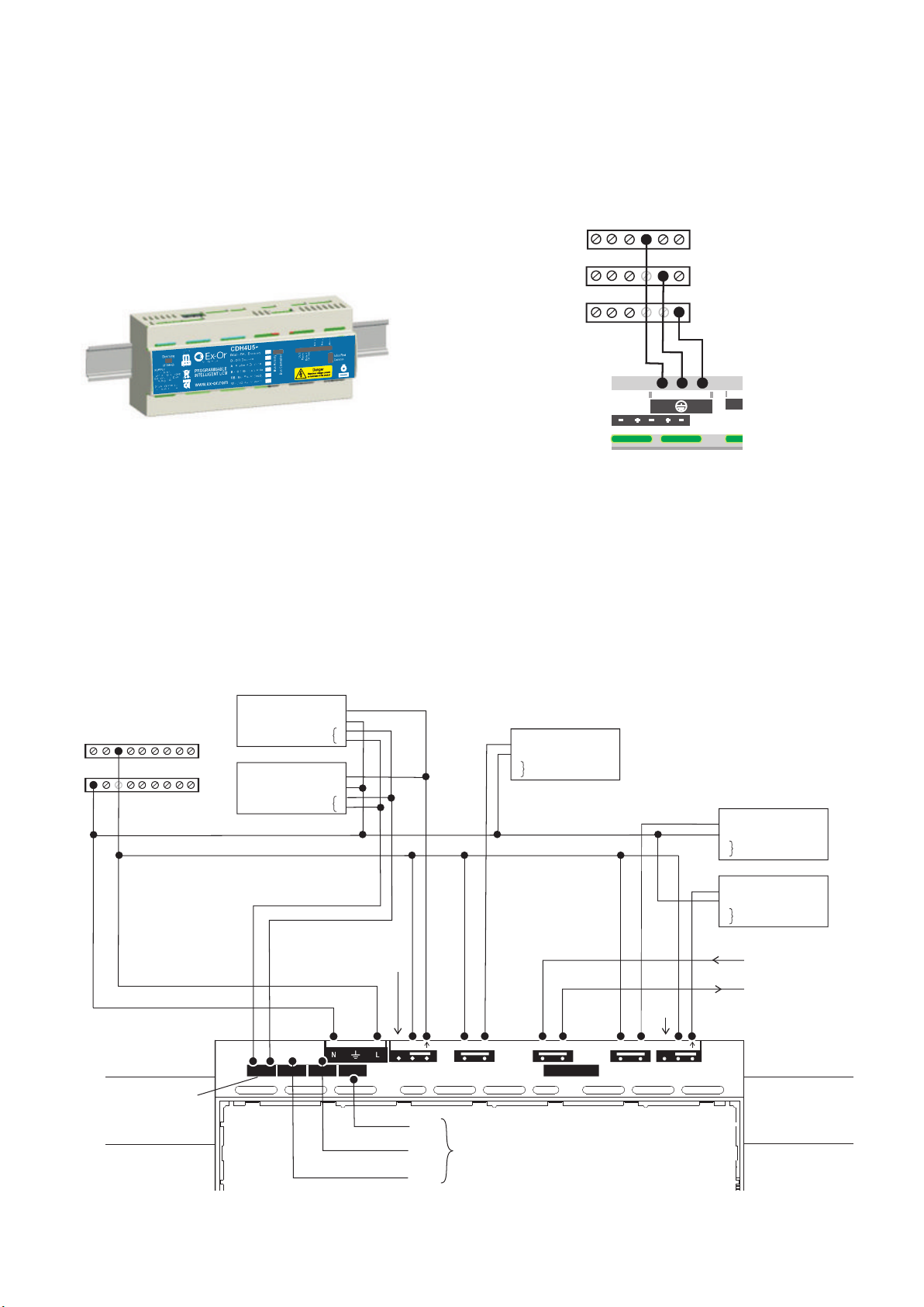
The CDH4U5 has provision to connect more than one supply from different phases in three different scenarios: a) Single Supply, b) Essential and non-essential
supplies and c) Two supplies equally likely to drop out .
Aux 3
a) Single Supply
Introduction
The CDH4U5 is an intelligent LCM providing connections for multiple
luminaires*, up to 5 presence detectors and up to 5 SELV inputs. The product
simplifies installation whilst providing an intelligent lighting control system.
Provision is made for 4 volt-free power outputs rated for 415V isolation.
Additionally, the unit features a switched output for Maintained Live to allow
initiation of Emergency Lighting Test. The CDH4U5 has the ability to operate
from dual supplies with the capability to modify its operating behaviour when
failure is detected on one of the supplies. This feature is described in greater
detail in application note AN4027.
*Note: Refer to Technical Data section to find out maximum allowable number
of luminaires.
Fixing
The CDH4U5 should be mounted in an enclosure with a DIN-rail.
Consideration should be given to access for installation and maintenance
when selecting the enclosure and location. The external enclosure DIN-rail
should comply with EN 60715.
Ballast
N
L
E
D
D
Ballast
N
L
E
D
D
Ballast
Ballast
Ballast
N
N
N
L
L
L
E
E
E
D
D
D
D
D
D
1
DETECTOR PORTS
2
3
4
5
B COM AB COM AB COM AB COM AB COM A
12
3
4
5
SELV SWITCH INPUTS
VOLT FREE CHANNELS
1 - 1 2 - 2
COMMS BUS
+ 4 -
+ 3 -
+ 2 -+ 1 -
DIMMING CHANNELS
N L
MAINS INPUT
VOLT FREE CHANNELS
N2 L2
N1 L1
CH2
ML
CH3CH1
CH4
DD
CH4
CH3
CH2
CH1
CH1
CH2
CH3
CH4
L
N
Do Not
Connect
Do Not
Connect
Earth not shown
for clarity
Dimming
Emergency
Luminaire
Maintained
Live
As shown above, the unit can be powered from a single supply; one or more luminaires may be connected to each channel.
-2-
Dimming
Dimming
Dimming
Dimming
Note: + and relevant for
analogue
versions only.
Dimming
Page 3
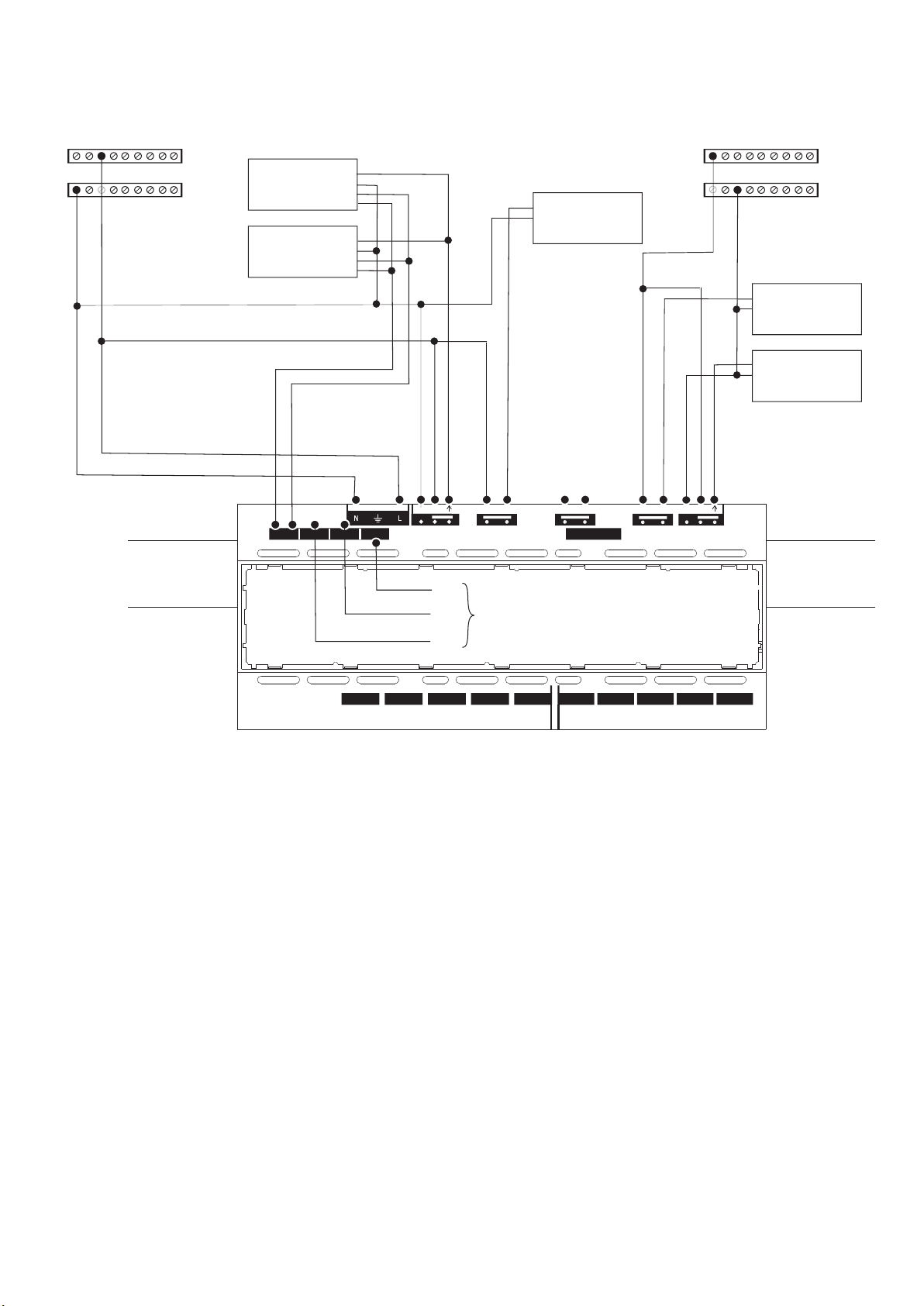
b) Essential and Non-Essential Supplies
As shown in the above diagram, the unit may also be wired with two different supplies where one of the supplies is guaranteed to be available referred to as
essential, while the other is referred as non-essential supply. The unit is recommended to be powered using the essential supply. As shown in the diagram, one
or more channels may be powered from either of the supplies.
Ballast
N
L
E
D
D
Ballast
N
L
E
D
D
Ballast
Ballast
Ballast
N
N
N
L
L
L
E
E
E
D
D
D
D
D
D
1
DETECTOR PORTS
2
3
4
5
B COM AB COM AB COM AB COM AB COM A
12
3
4
5
SELV SWITCH INPUTS
VOLT FREE CHANNELS
1 - 1 2 - 2
COMMS BUS
+ 4 -
+ 3 -
+ 2 -+ 1 -
DIMMING CHANNELS
N L
MAINS INPUT
VOLT FREE CHANNELS
N2 L2
N1 L1
CH2
ML
CH3CH1
CH4
DD
CH4
CH3
CH2
CH1
CH1
CH2
CH3
CH4
L
N
N
L
Not
used
NON-ESSENTIAL
SUPPLY
Earth not
shown for
clarity
ESSENTIAL
SUPPLY
Dimming
-3-
W5055E
Page 4

VOLT FREE CHANNELS
1 - 1 2 - 2
COMMS BUS
+ 4 -
+ 3 -
+ 2 -+ 1 -
DIMMING CHANNELS
N L
MAINS INPUT
VOLT FREE CHANNELS
N2 L2
N1 L1
CH2
ML
CH3CH1
CH4
CH4
CH3
CH1
Supply Failure Detection Mode
Channel 1 & Channel 4 are equipped with three-wire pluggable terminals with provision of connecting Neutral and Live from each supply. On detection of supply
failure on Channels 1 or 4, the unit enters into special operating mode. During this mode, the unit controls the output of luminares connected to the channel(s)
fed by the remaining supply according to the settings of Scene 5. During this special operating mode, the unit will continue to respond to switch inputs and
occupancy detection. The unit automatically reverts to normal behaviour once the failed supply has been restored.
Note: Please refer to the Commissioning section for programming the channel output settings of Scene 5.
As shown in the diagram above, two equal supplies may be connected from a single phase or different phases. In order to maintain constant supply to the unit an
external change-over contactor* is required. Line terminals from each of the supplies (N1, L1 and N2, L2) are connected via the change-over contactor. The
Live and Neutral outputs from the contactor are connected to the mains input of the unit. In the case of failure of one of the supplies, the change-over contactor
switches to the alternative supply to ensure continuous supply to the unit. As shown in the diagram above, one or more channels may be wired to run from either
supply.
* Such as Lovato BG series mini-contactor.
Note: Please refer to AN4027 for recommendations on wiring supplies to the change-over contactor and part number.
c) Two Supplies Equally Likely to Drop Out
Ballast
N
L
E
D
D
Ballast
N
L
E
D
D
Ballast
Ballast
Ballast
N
N
N
L
L
L
E
E
E
D
D
D
D
D
D
1
DETECTOR PORTS
2
3
4
5
B COM AB COM AB COM AB COM AB COM A
12
3
4
5
SELV SWITCH INPUTS
VOLT FREE CHANNELS
1 - 1 2 - 2
COMMS BUS
+ 4 -
+ 3 -
+ 2 -+ 1 -
DIMMING CHANNELS
N L
MAINS INPUT
VOLT FREE CHANNELS
N2 L2
N1 L1
CH2
ML
CH3CH1
CH4
DD
Emergency
Luminaire
Maintained
Live
CH4
CH3
CH2
CH1
CH1
CH2
CH3
CH4
L
N
Changeover
Contactor
N
L
N2 L2
L
L1
N1
N
Can be
derived
from
either
supply
SUPPLY 2SUPPLY 1
Earth not
shown for
clarity
Dimming
-4-
Page 5

Connecting Presence Detectors
The following SELV detectors are designed to interface to the CDH4U5:
MLS2500CDR Corner-mount Microwave presence detector with photocell, semi-flush mounted. Available with surface mount (SM suffix).
MLS2401CDR 360° Microwave presence detector with photocell, flush mounted. Available in surface mount version (SM suffix).
MLS2001CDR 360° PIR presence detector with photocell, flush mounted. Available in surface mount version (SM suffix).
MLSM2002CDR Controller for a 360° PIR detector with photocell. Used with the DHS OR DHW mini-head to form an integral luminaire-mounted unit.
Each connects to the CDH4U5 by means of an Ethernet-style RJ45 connector terminated patch lead which are available ready-made in 3m, 5m and 10m
lengths. Up to five detectors may be connected to a CDH4U5.
Positioning Presence Detectors
For information on installing and positioning detectors, please refer to the installation instructions provided with the particular detector.
Connecting Switches
The CDH4U5 is equipped with SELV switch inputs which will typically be two way, centre off, momentary rockers, (e.g. the MK K4900 range). The logical
function of a switch can be configured from a wide range of options and its action can be associated with any combination of channels. The switch connection
consists of a 3-pole pluggable terminal block comprising a common and two returns from normally open contacts. Four plugs are provided with each CDH4U5,
additional plugs can be ordered using the code CDHIP (5 pieces per pack).
.
Note that if the SELV status of any one of the switches
is compromised by reason of inadequate insulation or
segregation of the cabling, then the SELV status of all
other switches AND OF THE DETECTORS will also be
compromised.
B
Com
A
The recommended cable for use with the SELV switches is 3-core 300/500v 0.75mm≤ cable to CMA Reference 3183Y or for LS0H, to CMA Reference 3183B.
The maximum allowable cable length between the switch mechanism and the CDH4U5 terminal block is 100m.
Three separate single wires should not be used.
Connecting the Communications Bus (MLS)
2
It is imperative that the MLS Bus be wired in the correct type of cable. Normally it should be 1.5mm unscreened twisted pair. See Application Note AN4001.
Do not connect Mains to the MLS Bus.
For connection of Bus Power Supply variants, see also Supplementary Installation Instructions W5071.
-5-
VOLT FREE CHANNELS
1 - 1 2 - 2
COMMS BUS
+ 4 -
+ 3 -
+ 2 -+ 1 -
DIMMING CHANNELS
N L
MAINS INPUT
VOLT FREE CHANNELS
N2 L2
N1 L1
CH2
ML
CH3CH1
CH4
DD
2
In In
Out Out
MLS Bus 1 MLS Bus 2
Page 6

Commissioning
The LCM is commissioned using a dedicated programme running on a Windows-based computer. Commissioning settings may then be directly uploaded from
the computer to the LCM or transferred to an HP2000 hand-held programmer for easy upload on site.
Communication from the PC can be by means of a USB infrared transceiver which can signal directly to the LCM’s on-board infrared port over a short range or via
any attached presence detector from beneath (range: 1-3m).
The main parameters for configuration are tabulated below. These parameters may be re-programmed any number of times and all settings will be retained in
the event of a power loss.
SELV Switch Options Description
Sustain Caus es ass igned channels to act as if an occupancy detector continues to detect occupancy
Brighten Rais es light level . Works only with dim mable ballas ts.
Dim Lowers Light level . Works only with dimmab le ball asts.
Off Turns lamp OFF
Scene 01..06 Recalls Scene ass igned (any scene 01 to 06 as configured)
On Turns lamp ON
Partition Initiates logical partition of a room . Refer to AN4002 for more details
OneSwitch
Simple momentary pus h-to-make wallswitch that can be used to raise or lower the lighting level or toggle the output of
the unit ON or OFF. Short press toggles output ON and OFF; long press will ramp the light level Up or Down.
On-Dim Short Pres s will turn the output ON, long press will lower the light level
Off-Brighten Short Press will turn the output OFF, long press will raise the light level
On-Brighten Short Press will turn the output ON, long pres s will rais e the light level
Off-Dim Short Pres s will turn the output OFF, long press will lower the light level
Emergency Tst Initiates manual test of emergency luminaire by turning OFF the Maintained Live
Emergency End Res tores Maintained Live to end the Emergency Test
Description of Switch Input Options:
-6-
PARAMETERS OPTIONS
Per Box Parameters:
Switch A: 1-5, Switch B: 1 -5,
Switch 6A*, 6B*, 7A*, 7B*
User may choose any option for Switch A or Switch B from following:
Sustain / Brighten / Dim / Off / Scene 01..06 / On / Partition / OneSwitch / On-Dim / Off-Brighten / On-Brighten / Off-Dim /
Emergency Test / Emergency End (See separate table for detailed des criptio n of Switch Input options )
Detector 1-5: Range Max 100%, Max 75%, Max 50%
High 100%, High 75%, High 50%
Med 100%, Med 75%, Med 50%
Low 100%, Low 75%, Low 50%
Min 100%, Min 75%
Per Channel Parameters:
Ballast Type Non-Dimm ing, 1% DSI, 3% DSI, 10% DSI, 1% DALI, 3% DALI, 10% DALI
Assigned Detectors Detectors 1-5: Ass igned or not assigned to this channel
Assigned Photocell Photocell 1-5 (in Detectors 1-5): Assigned or not assigned to this channel
Assigned Switches Switch A & B: As si gned or not ass igned to this channel
Power Up On / Off
Res pons e Auto, Manual/Bus, Manual only
Off Delay (Main Tim e Delay) 10 seconds to 96 hours / Disabled
Bus Connect Yes / No
Zones 1-4 Zone num ber 1-100
Corridor 1-2: Begin Zone number 1-100
Corridor 1-2: End Zone num ber 1-100
Global 1-2 Rx Yes / No
Manual I/P (Local/Share for Each Switch)
Obey locally only / Obey locally and trans mit command on MLS bus
Start Lamps Max / Min
Entry Scene Scene 1-6
Lam p Max
100%, 90%, 80%, 70%, 50%, 45%, 40%, 35%, 30%, 25%, 20%, 15%, 10% Note: Not required for V F or SELV Outputs
When Vacant
Off until next occupancy detection
(Turn-Off Options )
Minimum, 25% or Scene 6 until next occupancy detection
Minimum, 25% or Scene 6 for 3 x Off Delay
Minimum, 25% or Scene 6 until the building is em pty
Fade to Off Yes / No
Bright Out Yes / No
Photocell
Regulate (100%, 90%, 80%, 70%, 60%, 50%) / Pass ive / Active / Disabled Note: Not required for VF or SELV Outputs
Set-Point Low (Photocell Lower Threshold)
0-1024 (used in Regulating Scene 1) Note: Not required for VF or SELV Outputs
Set-Point High (Photocell Upper Thres hold)
0-1024 (used in Regulating Scene 1) Note: Not required for VF or SELV Outputs
Scene 2 Output 0-100%
Scene 3 Output 0-100%
Scene 4 Output 0-100%
Scene 5 Output 0-100%
Scene 6 Output 0-100%
100 Hour Burn-in Burn-in 100hrs /Cancel/Resume - See Application Note AN4028
* Planned
Page 7

Product Applications
The CDH4U5 may be used in various different applications, e.g. warehouse, school, hospital etc having a single supply or two different supplies. For more
details on the differing applications, please refer to Application Note AN4027.
Width (W) = 213 mm
Height(H) = 62 mm
Depth(D) = 91 mm
Weight = 0.55kg approx
Technical Data
Operational supply: 230VAC ~50Hz/60Hz
Power consumption: 18W maximum
Product rating & recommended circuit protection: 16A or 20A MCB
Maximum load (per channel): 6A
Digital dimming ballasts per channel: 10 maximum
Digital dimming ballasts per LCM: 40 maximum
1-10V dimming ballasts per channel: 20mA (sinking only). See manufacturer's specification: worst case 10 Ballasts but Philips HF-R, for example,
20 Ballasts.
Maintained live output: 6A
Mains supply terminal capacity: 2x2.5mm≤ or 1x4mm≤
Override switch input connector: 2.5mm≤
MLS bus connector: 2.5mm≤
MLS bus cable: 1.5mm≤ unscreened twisted pair: see Application Note AN4001
Case material: Self-extinguishing blend PC/ABS
Case finish: Gray RAL 7035
IP rating: 20
Dimensions
9 m1m
62mm
3m21 m
Volt-free
Channels
Volt-free
Channels
Dimming
Channels
Comms
Bus (MLS)
Mains
Input
Detectors
Switches
Additional
Switches
Connections
Maintained
Live VF Output
-7-
Enclosure
An enclosure (K5612S MAG) is available for this product. It provides integral connection bars fitted with link.
It features a robust base together with an all-over front cover and moulded lid in an impact-resistant, flame-retardant thermoplastic.
Cable entry points are located on top, bottom, side and rear surfaces.
Colour: Magnolia
Dimensions: 306mm x 230mm x 110mm
Protection: BS EN 60529 to IP2XC
Page 8

W5055E
At the end of their useful life
the packaging and product
should be disposed of via a
suitable recycling centre.
Do not dispose of with normal
household waste.
Do not burn.
Ex-Or
Novar ED&S Limited
Haydock Lane, Haydock, Merseyside WA11 9UJ
Tel: +44 (0)1942 719229 Fax: +44 (0)1942 508753
Email: technicalsales.ex-or@honeywell.com
www.ex-or.com
Programmable Intelligent Lighting Control Modules (LCM):
CDH4U5 4-Channel LCM
CDH4U5-A 4-Channel LCM - Analogue Dimming
CDH4U5-D 4
CDH4U5-DALI 4
CDH4U5-B 4
-Channel LCM - DSI Dimming
-Channel LCM - DALI Dimming
-Channel LCM with MLS Bus
CDH4U5-BA 4-Channel LCM with MLS Bus - Analogue Dimming
CDH4U5-BD 4-Channel LCM with MLS Bus - DSI Dimming
CDH4U5-BDALI 4-Channel LCM with MLS Bus - DALI Dimming
CDH4U5-BAWL* 4-Channel LCM with MLS Bus, Wireless-switch enabled - Analogue Dimming
CDH4U5-BDWL* 4-Channel LCM with MLS Bus, Wireless-switch enabled - DSI Dimming
CDH4U5-BDALIWL* 4-Channel LCM with MLS Bus, Wireless-switch enabled - DALI Dimming
CDH4U5-RB 4-Channel LCM with MLS Bus Power Supply Unit
CDH4U5-RBA 4-Channel LCM with MLS Bus Power Supply Unit - Analogue Dimming
CDH4U5-RBD 4-Channel LCM with MLS Bus Power Supply Unit - DSI Dimming
CDH4U5-RBDALI 4-Channel LCM with MLS Bus Power Supply Unit - DALI Dimming
CDH4U5-RBAWL* 4-Channel LCM with MLS Bus Power Supply Unit, Wireless-switch enabled - Analogue Dimming
CDH4U5-RBDWL* 4-Channel LCM with MLS Bus Power Supply Unit, Wireless-switch enabled - DSI Dimming
CDH4U5-RBDALIWL* 4-Channel LCM with MLS Bus Power Supply Unit, Wireless-switch enabled - DALI Dimming
Plug-in Cards:
CDHDC Plug-in Digital Dimming Card
CDHAC Plug-in Analogue Dimming Card
CDHBC Plug-in MLS Bus Interface
CDHRB Plug-in MLS Bus Power Supply Unit
CDHWL* Plug-in Wireless EnOcean Card
Presence Detectors with photocell:
MLS2500CDR Corner-mount Microwave, semi-flush mounted
MLS2500CDRSM Corner-mount Microwave, surface mounted
MLS2401CDR 360° Microwave, flush mounted
MLS2401CDRSM 360° Microwave, surface mounted
MLS2001CDR 360° PIR, flush mounted
MLS2001CDRSM 360° PIR, surface mounted
MLSM2002CDR Control Module for integration within luminaire
DHS 360° PIR detector for use with MLSM2002CDR - silver bezel
DHW 360° PIR detector for use with MLSM2002CDR - white bezel
DHFK-S Flush-mounting Kit for integral detector (DHS) - silver
DHFK-W Flush-mounting Kit for integral detector (DHW) - white
Detector Patch Leads:
BT5E030GY 3m Patch Lead
BT5E050GY 5m Patch Lead
BT5E100GY 10m Patch Lead
Connectors:
CDHDOP 2-way Plug - blue - dimming outputs (2 pieces)
CDHSLOP 2-way Plug - black - switched live outputs (2 pieces)
CDHIP 3-way Plug - green - SELV switch inputs and auxiliary relay (5 pieces)
CDHBUSP 4-way Plug - red - MLS (1 piece)
CDHMIP 3-way Plug - black - mains input (1 piece)
CDH4VFP 3-way Plug - black - volt-free channels (2 pieces)
Ancillary Items:
UIRD1 USB Programming Dongle
RB2000 MLS Digital Bus Power Supply
RB2000LT MLS Digital Bus Power Supply 'Lite’
K5612S MAG Enclosure
* Planned - please contact Sales Department for latest information
Part Numbers
 Loading...