

Page 1
EN1I-6301
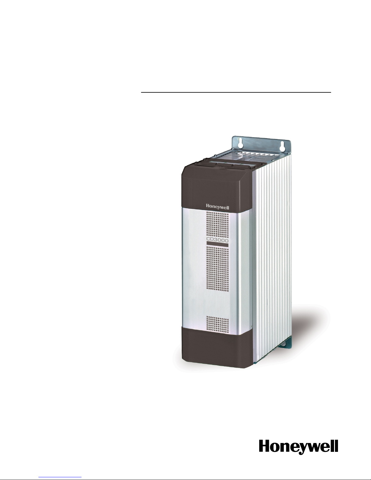
CD3000S-1PH
THYRISTOR UNIT
From 125A to 700A
USER’S MANUAL
Rev. 12/2004
Page 2

EN1I-6301
Page 3

User’s Manual CD3000S-1PH from 125A to 700A Honeywell
CD3000S-1PH Thyristor Unit from 125A to 700A
Index:
1. Glossary 4
1.1 Terminology 4
1.2 Input signal 4
1.3 Power feed back 4
1.4 What is a thyristor unit 4
2. Technical specifications 5
2.1 General Features 5
2.2 Input features 5
2.3 Output features 6
2.4 Derating curve 6
2.5 Fans 6
3. Ordering information 7
4. Installation and wiring information 8
4.1 Identification of the unit 8
4.2 Installation 8
4.3 Dimensions 9
4.4 Fixing Holes 10
5. Wiring Instructions 11
5.1 Removing the cover 11
5.2 Cabling detail 14
5.3 Wiring connection 16
5.4 LED Status Table 17
6. Start up 18
6.1 Auxiliary supply 19
6.2 Input configuration 20
7. Thyristor firing mode 21
7.1 Zero Crossing(ZC) 21
8. Fuses and fuseholder 22
8.1 Fuses and Fuse Code 22
9. Maintenance 23
9.1 Trouble Shooting 23
9.2 Repairing procedure 24
9.3 Fans 24
9.4 Servicing 24
9.5 Warranty conditions 24
1 www.honeywell.com/imc
Page 4

Honeywell CD3000S-1PH from 125A to 700A User’s Manual
CAUTION
Thyristor units are used in power industrial equipment. When the thyristor unit is working, there
are on the unit the following voltages
- Maximum main supply voltage on power terminals up to 600V.
- Auxiliary supply 230-460Vac.
- Fan voltage 230Vac 50/60Hz Power consumption 14W.
Don't remove the plastic cover which provides adequate protection against electric shock.
Don’t use this thyristor in aerospace and nuclear application.
Electric Shock Hazard (Risque the choque électrique)
When thyristor unit has been connected to main supply voltage and is switched off, before to touch
it be secure that the unit is isolated and wait at least one minu te to permit to discharge internal
capacitors. Thus be secure that:
• access to thyristor unit is only permitted to specialized personnel;
• the authorised personnel must read this manual before to have access to the unit;
• the access to the units must be denied to unauthorized personnel.
Important warnings(attention)
• Local regulations regarding electrical installation should be rigidly observed.
• Safety regulations must be rigidly observed.
• Don't bend components to maintain insulation distances.
• Protect the units from high temperature, humidity and vibrations.
• Don't touch components to prevent elettrostatichal discharges on them.
• Verify that all ratings are in line with real needs.
• If authorized personnel must measure voltage, current etc. on units, take away rings and other
jewels from fingers and hands.
• Authorized personnel working on thyristor unit under power supply voltage must work on
insulated board. Be secure that board is not connected to earth.
This listing does not represent a complete enumeration of all necessary safety cautions.
www.honeywell.com/imc 2
Page 5
User’s Manual CD3000S-1PH from 125A to 700A Honeywell
Protection(protection)
CD3000 thyristor family has a polymeric plastic cover in compliance to International specification
IP20. To understand if IP20 protection is sufficient should be evaluated the installation place where
the units are installed.
Open Type Equipment(équipment de type ouvert).
Maximum surrounding air temperature 40°C(Temperature de l’air environnante maximum 40°C).
Earth(terre)
CD3000 family has isolated heatsink. For safety connect the heatsink to earth to avoid shocks in
case that circuit board or thyristors lost insulation. Earth impedance should be correspondent to
local earth regulation. Periodically the earth efficiency should be inspected.
Electronic Supply(alimentation électronique)
CD3000 family electronic circuit should be supplied by dedicated voltage supply for all electronic
circuit but not in parallel with contactor's coil, solenoids and other inductive or capacitive loads. It's
recommended to use a shielded transformer.
Electromagnetic compatibility (compatibilité électromagnétique)
Our thyristor unit has an excellent immunity to electromagnetic interferences if all suggestions
contained in this manual are respected. In respect to a good Engineering practise, all inductive
loads like solenoids contactor coils should have a filter in parallel.
Emissions (emission)
All thyristor switching at high speed generate some radiofrequency disturbance. CD3000 serie
complies with EMC rules for CE mark. In many installations near electronic devices has not been
noted problems. If radiofrequency device at low frequency are used near the thyristor unit, some
precautions should be taken like line filters and shielded cables for input signal an d for load cables.
CU
LISTED
S
U
L
®
NOTE
We reserves the right to apply modifications to the our products without any advice.
3 www.honeywell.com/imc
Page 6
Honeywell CD3000S-1PH from 125A to 700A User’s Manual
1. Glossary
1.1 Terminology
V: voltage power supply.
I: the full circulating current in thyristor unit.
P: total load power.
1.2 Input signal
SSR: This input type is a square waveform generated by a temperature controller.
AN: Analog input.
IRS: Communication command.
1.3 Power feed back
Feedback: supply voltage fluctuation changes the power to the load. To overcome this effect the
voltage supplied to the load is measured and compared with power demand from controller, the
error signal is used to automatically hold the power at demanded level.
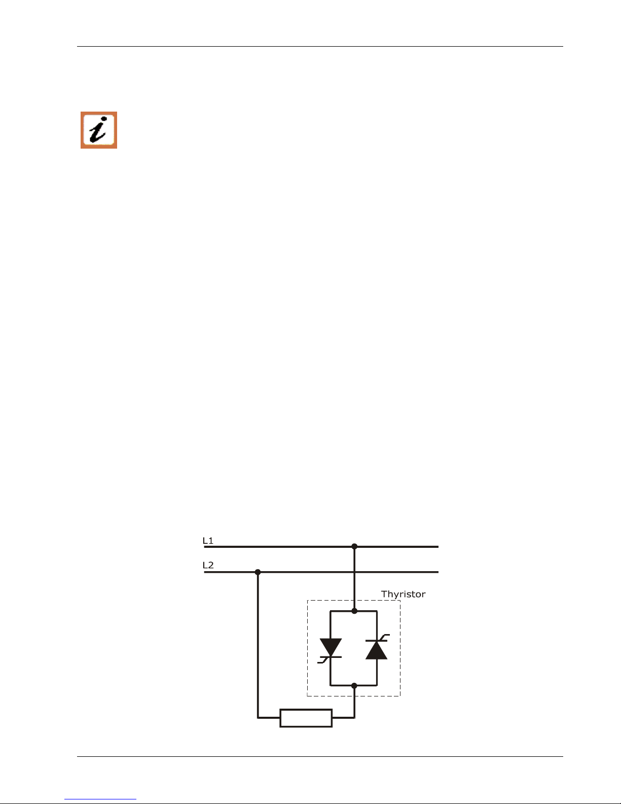
1.4 What is a thyristor unit
A thyristor unit is semiconductor device which acts as a switch formed by two thyristors in
antiparallel. To switch on the alternating current the input signal will be on and the thyristor will
switch off at first zero crossing voltage with no input signal. The benefits of thyristor units
compared with elettromechanical contactors are numerouses: no mooving parts, no maintenance
and capacity to switch very fast. Thyristors are the only solution to control transformers and
special loads that change resistance with temperature and with age.
LOAD
www.honeywell.com/imc 4
Page 7

User’s Manual CD3000S-1PH from 125A to 700A Honeywell
2. Technical specifications
2.1 General Features
Operating temperature 0÷45°C for higher temperature see derating curve
Voltage power supply 24V minimum, 480V max and 600V on request
Input signal SSR
Firing mode Zero Crossing (ZC)
Auxiliary voltage supply 230 Æ 200÷230V ±15%; 10 VA power consumption
460 Æ 300÷460V ±15%; 10 VA power consumption
Fan voltage supply 230V ±15%;
110V ±15% on request
Fuses Internal
Mounting
Bulk head mounting
Protection IP20
2.2 Input features
Input signal Maximum current drain ON condition OFF condition
SSR 12mA constant current ≥4V-max 30V ≤1V
5 www.honeywell.com/imc
Page 8
Honeywell CD3000S-1PH from 125A to 700A User’s Manual
2.3 Output features
Current Voltage range
Ripetitive peak
reverse voltage
Latching
current
Max peak
one cycle
Leakage
current
I
2
T value for
fusing
Frequency
range
Power
loss
Isolation
Voltage
(A) (V) (480V) (600V) (mAeff) (10msec.) (A) (mAeff) tp=10msec (Hz)
I=Inom
(W)
Vac
125 24÷600 1200 1600 450 1540 15 11300 47÷70 146 2500
150 24÷600 1200 1600 450 2000 15 19100 47÷70 162 2500
200 24÷600 1200 1600 300 4800 15 108000 47÷70 204 2500
300 24÷600 1200 1600 300 5250 15 128000 47÷70 320 2500
400 24÷600 1200 1600 200 7800 15 300000 47÷70 397 2500
500 24÷600 1200 1600 200 8000 15 306000 47÷70 530 2500
600 24÷600 1200 1600 1000 17800 15 1027000 47÷70 589 2500
700 24÷600 1200 1600 1000 17800 15 1027000 47÷70 712 2500
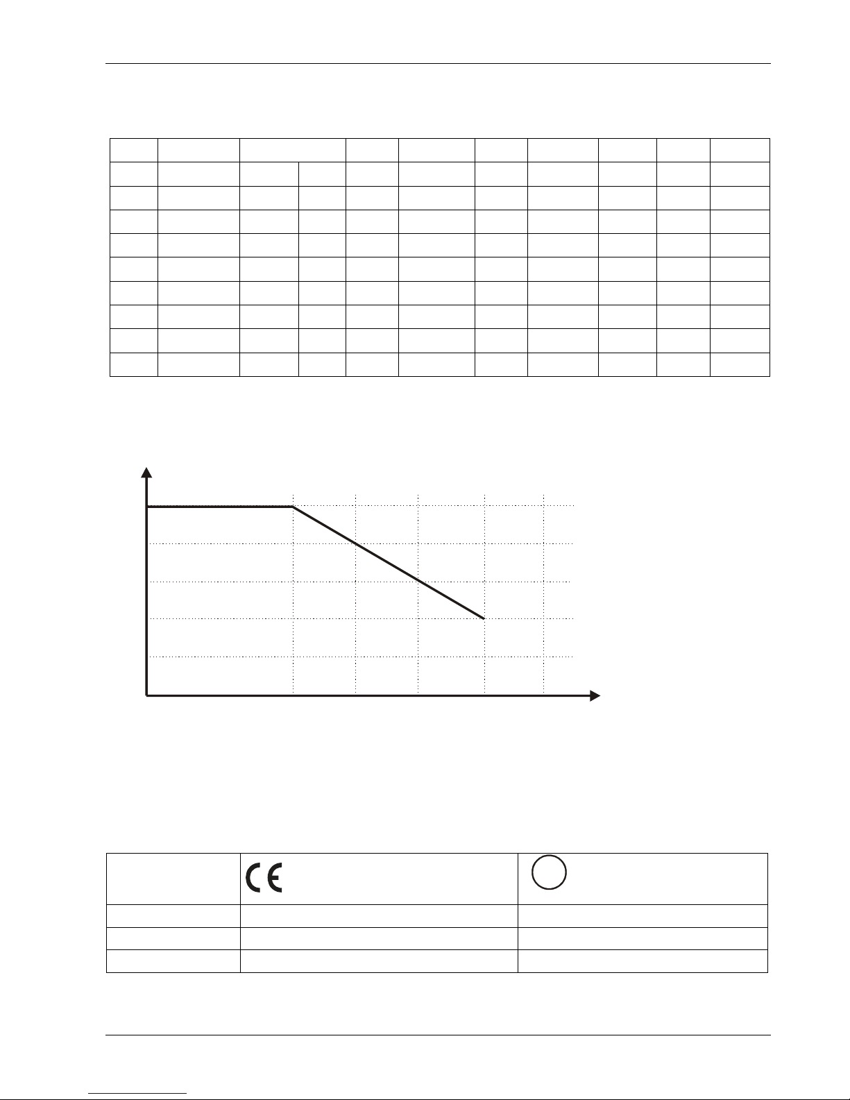
2.4 Derating curve
1
0.8
0.6
0.4
0.2
0
45 55 65 75 85
K
°
C
I = I x
K
NOMMAX
2.5 Fans
The thyristor units are equiped with a fan. The fan supply must be protected with a fuse.
Fan voltage supply is standard 230VAC ± 15% 50/60Hz or optional 110VAC ± 15% 50/60Hz.
The power consumption is given in the table below.
Size
Number of fans
CU
LISTED
S
U
L
®
Number of fans
125A up to 200A One Fan - 14W One Fan - 14W
300A up to 600A One Fan - 14W Two Fans - 30W
700A Two Fans - 30W Two Fans - 30W
www.honeywell.com/imc 6
Page 9

User’s Manual CD3000S-1PH from 125A to 700A Honeywell
3. Ordering information
Model CD3000S 1PH
1 2 3 4 5 6 7
CD3000S-1PH
Ex:CD3000S 1PH/ 150A/ 400V/ 480V/ 460V/ SSR/ ZC/ UL
1 Nominal CURRENT of CD3000S
125A 300A 600A
150A 400A 700A
200A 500A
2 Operating Load Voltage (incoming voltage supply)
Specify the value of the line supply.
3 Max VOLTAGE of CD3000S
480V
600V
The voltage on the identification label must be equal or more than
operating voltage. The minimum voltage supply to the load is 24V.
4 Auxiliary Voltage
230V 200÷230V ±15%; 10VA
460V 300÷460V ±15%; 10VA
600V 600V ±15%; 10VA (on request)
5 Input
SSR 4÷30VDC
6 Firing
ZC Zero Crossing
7 Options
FAN110
Fan voltage supply 110VAC ± 15% (std 230VAC ± 15%)
14W 50/60Hz
UL UL Certification
7 www.honeywell.com/imc
Page 10

Honeywell CD3000S-1PH from 125A to 700A User’s Manual
4. Installation and wiring information
4.1 Identification of the unit
Before to install the CD3000S unit examine for damages or deficiencies. Check that
the product features shown on CD3000S identification label corresponds to that
ordered.
An identification label provide all the informations regarding the factory settings of the unit. This
label is on the board inside the unit, as represented below:
Identification label
4.2 Installation
CD3000S unit should be always mounted in vertical position to improve air cooling on
heatsink. Maintain minimum distances in vertical and in horizontal as below
represented. Don’t install in proximity of hot elements and near units generating
electromagnetic interferences.
When more units are mounted inside a cubicle provide air circulation as below represented.
Sometimes it is necessary to provide a fan to have better air circulation.
www.honeywell.com/imc 8
Page 11

User’s Manual CD3000S-1PH from 125A to 700A Honeywell
4.3 Dimensions
Size W(mm) H(mm) D(mm)
125A (S9) 116 316 187
150A (S9) 116 316 187
200A (S9) 116 316 187
300A (S12) 137 520 270
400A (S12) 137 520 270
500A (S12) 137 520 270
600A (S12) 137 520 270
700A (S12) 137 520 270
9 www.honeywell.com/imc
Page 12

Honeywell CD3000S-1PH from 125A to 700A User’s Manual
4.4 Fixing Holes
A
B
C
Size A(mm) B(mm) C(mm)
125A (S9) 96 290 104
150A (S9) 96 290 104
200A (S9) 96 290 104
300A (S12) 97 495 97
400A (S12) 97 495 97
500A (S12) 97 495 97
600A (S12) 97 495 97
700A (S12) 97 495 97
www.honeywell.com/imc 10
Page 13

User’s Manual CD3000S-1PH from 125A to 700A Honeywell
5. Wiring Instructions
5.1 Removing the cover
To open the unit apply as follow.
For S12 size, you must open the cover to cable, to configure the unit and to view the fuses
For S9 size, you must open the cover to configure the unit and to view the fuses
Warning: this procedure can be done just by specialized personnel
CD3000S unit has isolated heatsink. For safety connect the heatsink to hearth using
its terminal with hearth symbol.
CD3000S can be susceptible to airborne interferences from near equipment or from interferences
on main supply, so a number of precautions must be taken.
• Contactors coils and chokes must have in parallel a RC filter and must be supplied with a
different voltage line.
• All input/output signal must use screened bifilar wires.
• Signal input and output must not routing in same cable try and must not be parallel.
• Local regulations regarding electrical installation should be rigidly observed.
11 www.honeywell.com/imc
Page 14

Honeywell CD3000S-1PH from 125A to 700A User’s Manual
5.1.1 Auxiliary Terminals
Before connect or disconnect, make sure that the power, control cables and wires are
insulated from the voltage
Terminal Description
1 Auxiliary supply voltage 230-460Vac (600V opt.)
2 N.C. not connected
3 Auxiliary supply voltage 230-460Vac (600V opt.)
4 N.C. not connected
5 Fan supply 230V (110V opt.)
6 Fan supply 230V (110V opt.)
7 Reset
8 Reset
9 + Input command signal SSR
10 - Input command signal SSR
11
∅ Volt GND (only on S12 size)
12 Output + 8Vdc stabilized, 1mA max (only on S12 size)
13 +Output command signal to CD3000 slave (only on S12 size)
14 - Output command signal to CD3000 slave (only on S12 size)
15 Not used
16 Not used
17 Not used
18 Not used
19 Not used
20 Not used
Auxiliary terminals
www.honeywell.com/imc 12
Page 15

User’s Manual CD3000S-1PH from 125A to 700A Honeywell
5.1.2 Power Terminals
Before connect or disconnect, make sure that the power, control cables and wires are
insulated from the voltage
Terminal Description
L2 Line Input
T2 Load Output
S9 power connection S12 power connection
L2
13 www.honeywell.com/imc
Page 16

Honeywell CD3000S-1PH from 125A to 700A User’s Manual
5.2 Cabling detail
Use 75°C copper (CU) conductor only, provided with the terminal type indicated below.
Current/courant
Torque/couple
Lb-in (N-m)
Wire
Range/cable
Wire
Terminal/terminal
125A, 150A,
200A,
265 (30)
1
3/0
Polymeric Terminal
Block M8
300A, 400A
500A
600A, 700A
505 (57.0) Bus Bar Bus Bar Adapter M10
www.honeywell.com/imc 14
Page 17

User’s Manual CD3000S-1PH from 125A to 700A Honeywell
Power terminals: wire details:
Current Supply
L1, L2 and L3
Load
T1, T2 and T3
Cable Cable
mm
2
AWG
Screw
M
mm
2
AWG
Screw
M
125A 50 1 M8 50 1 M8
150A 70 1/0 M8 70 1/0 M8
200A 95 3/0 M8 95 3/0 M8
300A 2 x 70 2 x 1/0 M10 2 x 70 2 x 1/0 M10
400A 2 x 95 2 x 3/0 M10 2 x 95 2 x 3/0 M10
500A Bus Bar 60 x 4 mm Bus Bar 60 x 4 mm
600A Bus Bar 60 x 5 mm Bus Bar 60 x 5 mm
700A Bus Bar 60 x 6 mm Bus Bar 60 x 6 mm
Auxiliary connectors and earth:
Current Auxiliary Supply Earth
Cable
Cable
mm
2
AWG
mm
2
AWG
Screw
M
125A 0,50 18 16 6 M6
150A 0,50 18 16 6 M6
200A 0,50 18 25 4 M8
300A 0,50 18 50 1 M8
400A 0,50 18 50 1 M8
500A 0,50 18 70 1/0 M8
600A 0,50 18 70 1/0 M8
700A 0,50 18 70 1/0 M8
15 www.honeywell.com/imc
Page 18

Honeywell CD3000S-1PH from 125A to 700A User’s Manual
5.3 Wiring connection
5.3.1 CD3000 125-700A
RESET 7
RESET 8
INPUT + 9
INPUT - 10
0V GND 11
+ 8V 12
SLAVE + 13
SLAVE - 14
15
16
17
18
L2 or N
L1
L2
230/460V 3
PE 4
FAN 5
FAN 6
230/460V 1
2
19
20
FAN SUPPLY 230V Std
INPUT SIGNAL
SSR
T2
**
AV AILABLES ONLY
ON S12 SIZE
NOTE: IMPORTANT
* The user installation must be protected by electromagnetic circuit
breaker or by fuse isalator.
** If the auxiliary voltage (written on the identification label) is different
from supply voltage (to the load), use an external transformer, as
reported above.
To work terminals 7-8 must be linked.
Fan voltage supply is standard 230VAC ±15% 50/60Hz or optional 110VAC ±15% 50/60Hz. For
power consumption see fan paragraph.
www.honeywell.com/imc 16
Page 19

User’s Manual CD3000S-1PH from 125A to 700A Honeywell
5.4 LED Status Table
LED STATUS DESCRIPTION
PW
(green led)
Auxiliary supply is not connect
Auxiliary supply is connect
ON
(green led)
OFF Condition (Load IS NOT Powered)
ON Condition (Load IS Powered)
= Light OFF
= Light ON
17 www.honeywell.com/imc
Page 20

Honeywell CD3000S-1PH from 125A to 700A User’s Manual
6. Start up
Before to supply the thyristor unit:
• verify that load current equal or less than nominal;
For resistive load For inductive load
I
V
P
tot
=
I
P
tot
=
V
cos
φ
• verify that there is no short circuit on load;
• verify that main voltage equal or less than nominal;
• verify that all auxiliary connections are right;
• fan voltage equal than nominal (230V std , 110V optional)
After which supply thyristor unit giving the maximum input signal and verify that load current is
equal or less than thyristor unit nominal current.
Warning: this procedure can be done just by specialized personnel.
The thyristor unit is delivered configured and tuned in line with customer
requirements. If it’s necessary to change on site the configuration, procede as below
specified.
www.honeywell.com/imc 18
Page 21

User’s Manual CD3000S-1PH from 125A to 700A Honeywell
6.1 Auxiliary supply
Warning: this procedure can be done just by specialized personnel.
To change auxiliary supply voltage sold the correct link-jumper on main PCB.
Auxiliary supply jumpers for S9 size
Auxiliary supply jumpers for S12 size
J11
J10
J9
J11
J10
J9
230V Auxiliary supply
To set the auxiliary power
supply to 230V, close J9 and
J11 and open J10 as shown
below.
460V Auxiliary supply
To set the auxiliary power
supply to 460V, close J10
and open J9 and J11 as
shown below.
600V Auxiliary supply
This is a special version on request.
In this case the unit is supplied
already configured.
J11
J10
J9
J11
J10
J9
J11
J10
J9
19 www.honeywell.com/imc
Page 22

Honeywell CD3000S-1PH from 125A to 700A User’s Manual
6.2 Input configuration
Warning: this procedure can be done just by specialized personnel.
Location of input selection jumpers for S9 size
Location of input selection jumpers for S12 size
Jumpers Configuration
MAIN PCB
Input J7 J16 J17 J13
SSR
ABC
ABC
ABC
FITTED
www.honeywell.com/imc 20
Page 23

User’s Manual CD3000S-1PH from 125A to 700A Honeywell
7. Thyristor firing mode
SSR fr om c o ntroller
LOAD VOLTAGE (V)
VOLTAGE SUPPLY (V)
ZERO CROSSING
7.1 Zero Crossing(ZC)
ZC firing mode is used with Logic Output
from temperature controllers and the
Thyristor operate like a contactor. The Cycle
time is performed by temperature controller.
ZC minimize interferences because the
Thyristor unit switch ON-OFF at zero voltage.
21 www.honeywell.com/imc
Page 24

Honeywell CD3000S-1PH from 125A to 700A User’s Manual
8. Fuses and fuseholder
8.1 Fuses and Fuse Code
CD3000S unit must be protected by fuses against short circuit selecting the proper I²t that must
be lower than thyristor one. The same caution must be taken if Circuit Breaker is used. Remember
that is very difficult to protect the thyristor if this choise is done.
WARNING!! Equipment short circuit protected by Semiconductor Fuse type
with proper I
2
t
Bussmann Div - Cooper (UK) Ltd
(200 kA
RMS
Symmetrical A.I.C.)
Ferraz Shawmut SA
(200 kA
RMS
Symmetrical A.I.C.)
Sizes
Fuse Mod. No.
/modéle fusible
Current
(A
RMS
)
I²t
(A2sec)
V ac Fuse Mod. No.
/modéle fusible
Current
(A
RMS
)
I²t
(A2sec)
Vac
125A 200 FEE 200 11400 660
6,6 URY 000
BS88/200
200 16000 660
150A 200 FEE 200 11400 660
6,6 URY 000
BS88/200
200 16000 660
300A 350 FM 350 105000 660
6,6 URZ 000
BS88 Z 350
350 85000 660
400A 550 FMM 550 215000 660
6,6 URZ 000
BS88 Z 550
550 208000 660
500A 700 FMM 700 420000 660
6,6 URZ 000
BS88 Z 700
700 340000 660
600A 2x 450 FMM 450 105000 660
6,6 URZ 2x000
BS88 Z 450
2X450 208000 660
700A 2x 450 FMM 450 105000 660
6,6 URZ 2x000
BS88 Z 700
2X450 208000 660
High speed fuses are only used for the thyristor protection and can not be used to
protect the installation.
The user installation must be protect by electromagnetic circuit breaker or by fuse
isolator.
The warranty of thyristor is null if no proper fuses are used. See tab above.
www.honeywell.com/imc 22
Page 25

User’s Manual CD3000S-1PH from 125A to 700A Honeywell
9. Maintenance
9.1 Trouble Shooting
Small problems sometimes can be solved locally with the help of the below tab of t rouble shootin g.
If you don’t succeed, contact us or your nearest distributor.
Symptom LED Indication Possible reasons of the
symptom
Actions
Green LED (PWR)
is always light off.
No voltage auxiliary power
supply to terminals 1-3
(see wiring diagram).
Give auxiliary voltage supply to
terminals 1-3.
Thyristor unit
doesn’t go in
conduction with
input signal.
Green LED (PWR)
light on and green
LED (ON) in off
condition.
No input signal.
Reversed polarities of input
signal.
Reset contact in open
condition (see wiring
diagram).
Provide to give input signal.
Reverse the input signal polarity.
Make link on reset terminals.
Load current flows
also with no input
signal.
Green LED (ON)
always in off
condition.
Short circuit on thyristor.
Wrong connection.
Substitute the thyristor. Check that
load is not in short circuit.
23 www.honeywell.com/imc
Page 26

Honeywell CD3000S-1PH from 125A to 700A User’s Manual
9.2 Repairing procedure
• Phone to us.
• Explain to Service Engineer the problem because sometimes it can be solved with a phone call.
• If this is not possible ship the unit to us or to your distributor.
• Write a fault description and give the name of your personnel to which refer.
• Use a rugged packaging to ship the unit.
9.3 Fans
The thyristor unit with forced ventilation uses fans that rotate permanently when the unit is
supplied. In case of accidental fan failure, there is an over heating temperature on heatsink. In this
case to give protection to thyristor there is a thermal switch properly setted. The function of this
switch is to open the input signal until the h eatsink temperature falls below the setted value. This
means that also with input signal in ON condition the unit is switched OFF and the system can not
work at full power. For these reason is important to control periodically the fan status checking
that is rotating.
9.4 Servicing
In order to have correct cooling, the user must clean the heatsink and the protective grill of fan.
The frequence of this servicing depends on environmenta l pollution.
Check periodically also if the screw for the power cables and safety earth are tightened correctly
9.5 Warranty conditions
We gives a 12 months warranty to its products. The warranty is limited to repairing and parts
substitution in our factory and does exclude products not properly used and fuses.
Warranty does not includes products with serial numbers deleted. The faulty product should be
shipped to us at your cost and our Service will evaluate if product is un d er warranty terms.
Substituted parts remains our property.
www.honeywell.com/imc 24
Page 27

User’s Manual CD3000S-1PH from 125A to 700A Honeywell
Sales and Service
For application assistance, current specifications, pricing, or name of the nearest Authorized Distributor, contact one of
the offices below.
Warranty/Remedy
Honeywell warrants goods of its manufacture as being free of defective materials and faulty work-manship. Contact your
local sales office of warranty information. If warranted goods are returned to Honeywell during the period of coverage,
Honeywell will repair of replace without charge those items it finds defective. The foregoing is Buyer’s sole remedy
and is in lieu of all other warranties, expressed or implied, including those of merchantability and fitness for
a particular purpose. Specifications may change without notice. The information we supply is believed to be accurate
and reliable as of printing. However, we assume no responsibility for its use. While we provide application assistance
personally, through our literature and the Honeywell website, it is up to the customer to determine the suitability of the
product in the application.
ASIA PACIFIC
Control Products
Asia Pacific Headquarters
Phone: +(65) 6355-2828
Fax: +(65) 6445-3033
Australia
Honeywell Limited
Phone: +(61) 2-9370-4500
FAX: +(61) 2-9370-4525
Toll Free 1300-36-39-36
Toll Free Fax: 1300-36-04-70
China – PRC - Beijing
Honeywell China Inc.
Phone: +(86-10) 8458-3280
Fax: +(86-10) 8458-3102
China – PRC - Shanghai
Honeywell China Inc.
Phone: (86-21) 6237-0237
Fax: (86-21) 6237-1237
China - Hong Kong S.A.R.
Honeywell Ltd.
Phone: +(852) 2953-6412
Fax: +(852) 2953-6767
China – PRC - Chengdu
Honeywell China Inc.
Phone: +(86-28) 6786-348
Fax: +(86-28) 6787-061
China – PRC - Guangzhou
Honeywell China Inc.
Phone: +(86-20) 3879-1169
Fax: +(86-20) 3879-1269
China – PRC - Shenzhen
Honeywell China Inc.
Phone: +(86) 755-518-1226
Fax: +(86) 755-518-1221
Indonesia
Honeywell Indonesia Pte Ltd.
Phone: +(62) 21-535-8833
FAX: +(62) 21-5367 1008
India
TATA Honeywell Ltd.
Phone: +(91) 20 687
0445/0446
Fax: +(91) 20 681 2243/ 687
5992
Japan
Honeywell Inc
Phone: +(81) 3 5440 1425
Fax: +(81) 3 5440 1368
South Korea
Honeywell Korea Co Ltd
Phone: +(822) 799-6167
Fax: +(822) 792-9013
Malaysia
Honeywell Engineering
Sdn Bhd
Phone: +(60-3) 79584988
Fax: +(60-3) 7958-8922
New Zealand
Honeywell Limited
Phone: +(64-9) 623-5050
Fax: +(64-9) 623-5060
Toll Free (0800) 202-088
Philippines
Honeywell Systems
(Philippines) Inc.
Phone: +(63-2) 636-1661
/1662
Fax: +(63-2) 638-4013
Singapore
Honeywell South East
Asia
Phone: +(65) 6355-2828
Fax: +(65) 6445-3033
Thailand
Honeywell Systems
(Thailand) Ltd.
Phone: +(662) 693-3099
FAX: +(662) 693-3085
Taiwan R.O.C.
Honeywell Taiwan Ltd.
Phone: +(886-2) 22451000
FAX: +(886-2) 22453242
EUROPE
Austria
Honeywell Austria GmbH
Phone: +43 (316)400123
FAX: +43 (316)40017
Belgium
Honeywell SA/NV
Phone:
+31(0)205656999
FAX: +31(0)165330746
Bulgaria
Honeywell EOOD
Phone: +(359) 2 79 40
27
FAX: +(359) 2 79 40 90
Czech Republic
Honeywell spol. s.r.o.
Phone: +420-543245014
FAX: +420-54324-5011
Denmark
Honeywell A/S
Phone: +(45) 39 55 55 55
FAX: +(45) 39 55 55 58
Finland
Honeywell OY
Phone: +358 (3) 2727625
FAX: +358 (3) 2728600
France
Honeywell SA
Phone: +33 (0)1 60198075
FAX: +33 (0)1 60198201
Germany
Honeywell AG
Phone: +49 (69)8064336
FAX: +49 (69)806497336
Hungary
Honeywell Kft.
Phone: +36-1-451 4335
FAX: +36-1-451 4343
Italy
Honeywell S.p.A.
Phone: +39 02 9214 6503
FAX: +39 0292146377
The Netherlands
Honeywell B.V.
Phone: +31(0)205656999
FAX: +31(0)165330746
Norway
Honeywell A/S
Phone: (45) 39 55 55 55
Poland
Honeywell Sp. zo.o
Phone: +48-22-6060900
FAX: +48-22-6060901
Portugal
Honeywell Portugal Lda
Phone: +351 21 424 5000
FAX: +351 21 424 50 99
Romania
Honeywell Bucharest
Phone: 40212110076
FAX: +40 (40212103375)
Commonwealth of
Independent States (CIS)
Z.A.O. Honeywell
Phone: +(7 095) 796 98 36
FAX: +(7 095) 796 98 93
Slovak Republic
Honeywell s.r.o.
Phone: +421-2-58247 410
FAX: +421-2-58247 415
Spain
Honeywell S.A.
Phone: +34 (0)91313 61 00
FAX: +34 (0)91313 61 30
Sweden
Honeywell AB
Phone: +(46) 8 775 55 00
FAX: +(46) 8 775 56 00
Switzerland
Honeywell AG
Phone: +41 18552448
FAX: +(41) 1 855 24 45
Turkey
Honeywell Turkey A.S.
Phone: +90 216 575 6600
FAX: +90 216 575 6637
United Kingdom
Honeywell Control Systems
Ltd
Phone: +(44) 1698 481730
FAX: +(44) 1698 481276
MIDDLE EAST
Abu Dhabi U A E
Middle East Headquarters
Honeywell Middle East Ltd
Phone: +971 2 4041220
FAX: +971 2 4432536
Sultanate of Oman
Honeywell & Co Oman LLC
Phone: +968 701397
FAX +968 787351
Egypt
Honeywell Egypt Ltd
Phone: +202 4514460 /1/
2/ 3/ 4/ 5/ 6
FAX : +2024514467
Saudia Arabia
Honeywell Turki Arabia
Limited
Phone: +966-3-341-0140
Fax: +966-3-341-0216
Kuwait
Honeywell Kuwait KSC
Phone: +965 2421327
AFRICA
Mediterranean & African
Distributors
Honeywell SpA
Phone: +39 (02) 250 10
604
FAX: +39 (02) 250 10 659
South Africa (Republic of)
Honeywell Southern Africa
Honeywell S.A. Pty. Ltd
Phone: +27 11 6958000
FAX +27 118051504
NORTH AMERICA
Canada
Honeywell LTD
Phone: 1-800-737-3360
FAX: 1-800-565-4130
USA
Honeywell
Control Products,
International Headquarters
Phone: 1-800-537-6945
1-815-235-6847
FAX: 1-815-235-6545
E-mail:
info.sc@honeywell.com
LATIN AMERICA
Argentina
Honeywell S.A.I.C.
Phone: +(54-11) 4383-3637
FAX: +(54-11) 4325-6470
Brazil
Honeywell do Brasil & Cia
Phone: +(55-11) 7266-1900
FAX: +(55-11) 7266-1905
Chile
Honeywell Chile, S.A.
Phone: +(56-2) 233-0688
FAX: +(56-2) 231-6679
Mexico
Honeywell S.A. de C.V.
Phone: +(52) 55 5259-1966
FAX: +(52) 55 5570-2985
Puerto Rico
Honeywell Inc.
Phone: +(809) 792-7075
FAX: +(809) 792-0053
Trinidad
Honeywell Inc
Phone: +(868) 624-3964
FAX: +(868) 624-3969
Venezuela
Honeywell CA
Phone: +(58-2) 238-0211
FAX: +(58-2) 238-3391
25 www.honeywell.com/imc
 Loading...