

Page 1
EN1I-6310
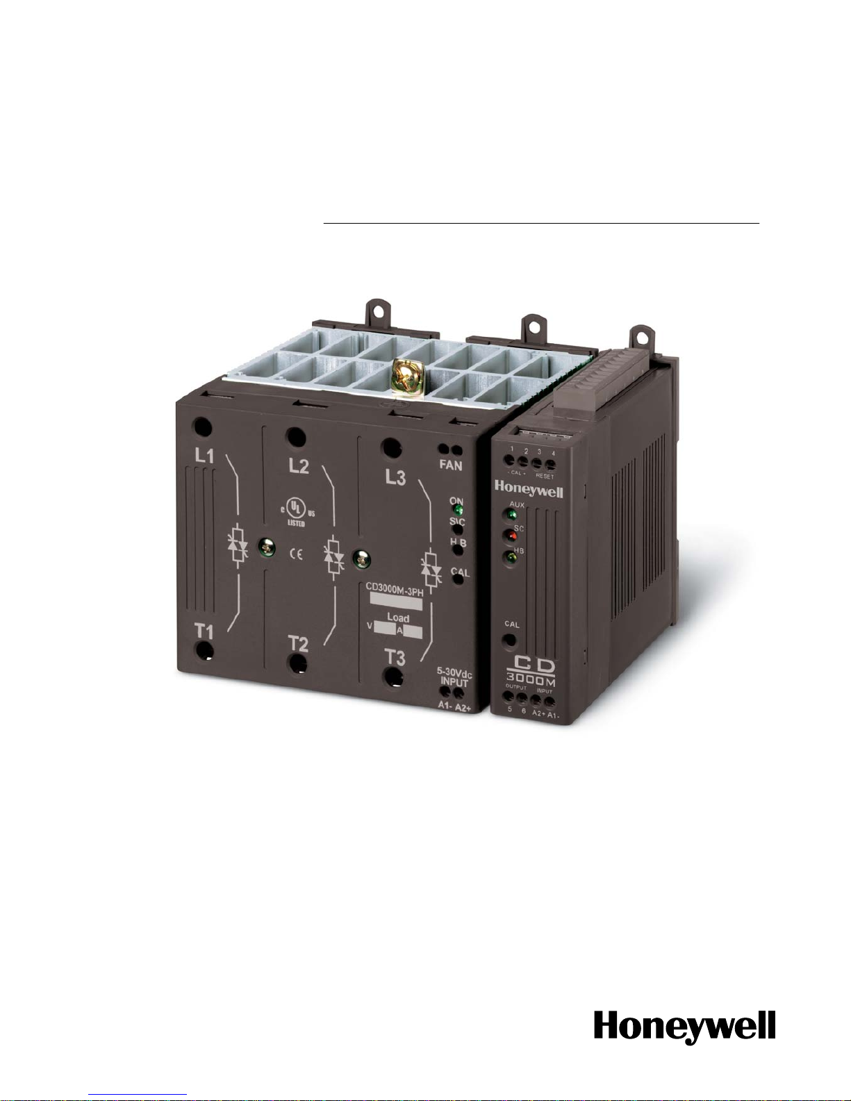
CD3000M-3PH
THYRISTOR UNIT
Up To 90A
USER’S MANUAL
Rev. 12/2004
Page 2

EN1I-6310
Page 3

User’s Manual CD3000M-3PH up to 90A Honeywell
1 www.honeywell.com/imc
CD3000M-3PH Thyristor Unit up to 90A
Index:
1. Glossary 5
1.1 Terminology 5
1.2 Input signal 5
1.3 Power feed back 5
1.4 What is a thyristor unit 5
2. Technical specifications 6
2.1 General Features: 6
2.2 Input features 6
2.3 Output features 7
2.4 Derating curve 7
3. Ordering information 8
4. Installation and wiring information 9
4.1 Identification of the unit 9
4.2 Installation 9
4.3 Dimensions 10
4.4 CT dimensions (Heater Break HB) 10
4.5 Fixing Holes 11
5. Wiring Instructions 12
5.2 Cabling detail 14
5.3 Wiring connections 16
5.4 LED Status Table 19
6. START UP 20
6.1 To remove the board 21
6.2 Auxiliary supply 22
6.3 Analog input 23
6.4 Heater Break Alarm 25
7. Thyristor firing mode 30
7.1 Zero Crossing (ZC) 30
7.2 Burst Firing (BF) 30
7.3 Configurator 31
8. Fuse and fuseholder for UL certification unit 33
8.1 Fuse and Fuse Code 33
8.2 FuseHolder size 34
9. Fuse and fuseholder for CE mark unit 35
9.1 Fuse and Fuse Code 35
9.2 FuseHolder size 36
Page 4

Honeywell CD3000M-3PH up to 90A User’s Manual
www.honeywell.com/imc 2
10. Modbus communication 37
10.1 Physical requirements 37
10.2 ModBus RTU protocol 37
10.3 Word parameters 42
10.4 Thyristor unit Configuration 47
10.5 Address configuration 51
11. Maintenance 54
11.1 Trouble Shooting 54
11.2 Repairing procedure 55
11.3 Fans 55
11.4 Servicing 55
11.5 Warranty conditions 55
Page 5

User’s Manual CD3000M-3PH up to 90A Honeywell
3 www.honeywell.com/imc
CAUTION
Thyristor units are used in power industrial equipment. When the thyristor unit is working, there
are on the unit the following voltages
- Maximum main supply voltage on power terminals up to 600V.
- Auxiliary supply 230-460Vac.
- Fan voltage 230Vac 50/60Hz Power consumption 14W.
Don't remove the plastic cover which provides adequate protection against electric shock.
Don’t use this thyristor in aerospace and nuclear application.
Electric Shock Hazard (Risque the choque électrique)
When thyristor unit has been connected to main supply voltage and is switched off, before to touch
it be secure that the unit is isolated and wait at least one minu te to permit to discharge internal
capacitors. Thus be secure that:
• access to thyristor unit is only permitted to specialized personnel;
• the authorised personnel must read this manual before to have access to the unit;
• the access to the units must be denied to unauthorized personnel.
Important warnings(attention)
• Local regulations regarding electrical installation should be rigidly observed.
• Safety regulations must be rigidly observed.
• Don't bend components to maintain insulation distances.
• Protect the units from high temperature, humidity and vibrations.
• Don't touch components to prevent elettrostatichal discharges on them.
• Verify that all ratings are in line with real needs.
• If authorized personnel must measure voltage, current etc. on units, take away rings and other
jewels from fingers and hands.
• Authorized personnel working on thyristor unit under power supply voltage must work on
insulated board. Be secure that board is not connected to earth.
This listing does not represent a complete enumeration of all necessary safety cautions.
Page 6
Honeywell CD3000M-3PH up to 90A User’s Manual
www.honeywell.com/imc 4
Protection(protection)
CD3000 thyristor family has a polymeric plastic cover in compliance to International specification
IP20. To understand if IP20 protection is sufficient should be evaluated the installation place where
the units are installed.
Open Type Equipment(équipment de type ouvert).
Maximum surrounding air temperature 40°C(Temperature de l’air environnante maximum 40°C).
Earth(terre)
CD3000 family has isolated heatsink. For safety connect the heatsink to earth to avoid shocks in
case that circuit board or thyristors lost insulation. Earth impedance should be correspondent to
local earth regulation. Periodically the earth efficiency should be inspected.
Electronic Supply(alimentation électronique)
CD3000 family electronic circuit should be supplied by dedicated voltage supply for all electronic
circuit but not in parallel with contactor's coil, solenoids and other inductive or capacitive loads. It's
recommended to use a shielded transformer.
Electromagnetic compatibility (compatibilité électromagnétique)
Our thyristor unit has an excellent immunity to electromagnetic interferences if all suggestions
contained in this manual are respected. In respect to a good Engineering practise, all inductive
loads like solenoids contactor coils should have a filter in parallel.
Emissions (emission)
All thyristor switching at high speed generate some radiofrequency disturbance. CD3000 serie
complies with EMC rules for CE mark. In many installations near electronic devices has not been
noted problems. If radiofrequency device at low frequency are used near the thyristor unit, some
precautions should be taken like line filters and shielded cables for input signal an d for load cables.
CU
LISTED
S
U
L
®
NOTE
We reserves the right to apply modifications to the our products without any advice.
Page 7
User’s Manual CD3000M-3PH up to 90A Honeywell
5 www.honeywell.com/imc
1. Glossary
1.1 Terminology
V: voltage power supply.
I: the full circulating current in thyristor unit.
P: total load power.
1.2 Input signal
SSR: This input type is a square waveform generated by a temperature controller.
AN: Analog input.
IRS: Communication command.
1.3 Power feed back
Feedback: supply voltage fluctuation changes the power to the load. To overcome this effect
the voltage supplied to the load is measured and compared with power demand from
controller, the error signal is used to automatically hold the power at deman d ed level.
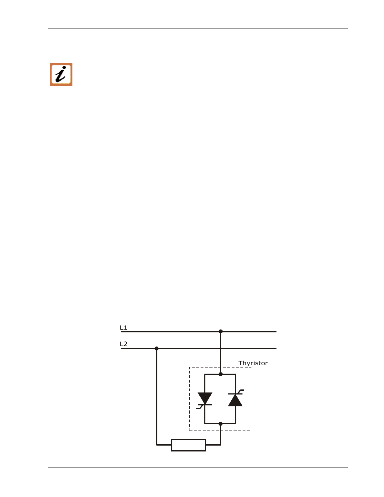
1.4 What is a thyristor unit
A thyristor unit is semiconductor device which acts as a switch formed by two thyristors in
antiparallel. To switch on the alternating current the input signal will be on and the thyristor will
switch off at first zero crossing voltage with no input signal. The benefits of thyristor units
compared with elettromechanical contactors are numerouses: no mooving parts, no maintenance
and capacity to switch very fast. Thyristors are the only solution to control transformers and
special loads that change resistance with temperature and with age.
LOAD
Page 8

Honeywell CD3000M-3PH up to 90A User’s Manual
www.honeywell.com/imc 6
2. Technical specifications
2.1 General Features:
Operating temperature
0÷40°C for higher temperature see derating curve
Voltage power supply 24V minimum, 480V max and 600V on request
Input signal SSR
4÷20 mA
0÷10V
potentiometer (10k ohm)
customer configurable with automatic zero/span calibration
Firing mode One of these firing modes can be configured on line via serial port
Zero Crossing (ZC)
Burst Firing (BF)
Auxiliary voltage supply
230V range (230 ±15%) 10VA
460V range (380 –15%) ÷ (460 +15%); 10VA
(sincronized with supply Voltage)
Fan voltage supply
230V range (230 ±15%) 10VA
460V range (380 –15%) ÷ (460 +15%); 10VA
(sincronized with supply Voltage)
Heather break alarm Discrimination better than 20%. Circuit microprocessor based to
diagnose partial or total load failure and short circuit on Thyristors.
Latching alarm plus reset. Relay output 0,5A at 125V
Line Drop Voltage Automatic compensation ±15% of supply voltage with analog input
Mounting Bulk head mounting
Protection IP20
2.2 Input features
Input signal
Maximum
current drain
Input
Impedance
ON condition OFF condition
SSR 5mA constant current ≥4V - max 30V ≤1V
Analog 0÷10V - 8200 ohm
Analog 4÷20mA - 100 ohm
Potentiometer
10K ohm
8200 ohm
Page 9
User’s Manual CD3000M-3PH up to 90A Honeywell
7 www.honeywell.com/imc
2.3 Output features
NA=not Available
Current Voltage
range
Ripetitive peak
reverse voltage
Latching
current
Max peak
one cycle
Leakage
current
I2T value
thyristor
Frequency
range
Power
loss
Isolation
Voltage
(A) (V) (480V) (600V) (mAeff)
(10msec.)
(A)
(mAeff) tp=10msec (Hz)
I=Inom
(W)
Vac
15 24÷480 1200 1200 150 230 15 610 47÷70 54 2500
30 24÷600 1200 1600 250 600 15 1800 47÷70 108 2500
45 24÷600 1200 1600 250 600 15 1800 47÷70 162 2500
60 24÷600 1200 1600 250 1000 15 4750 47÷70 216 2500
75 24÷600 1200 1600 450 1540 15 11300 47÷70 270 2500
90 24÷600 1200 1600 450 2000 15 19100 47÷70 324 2500
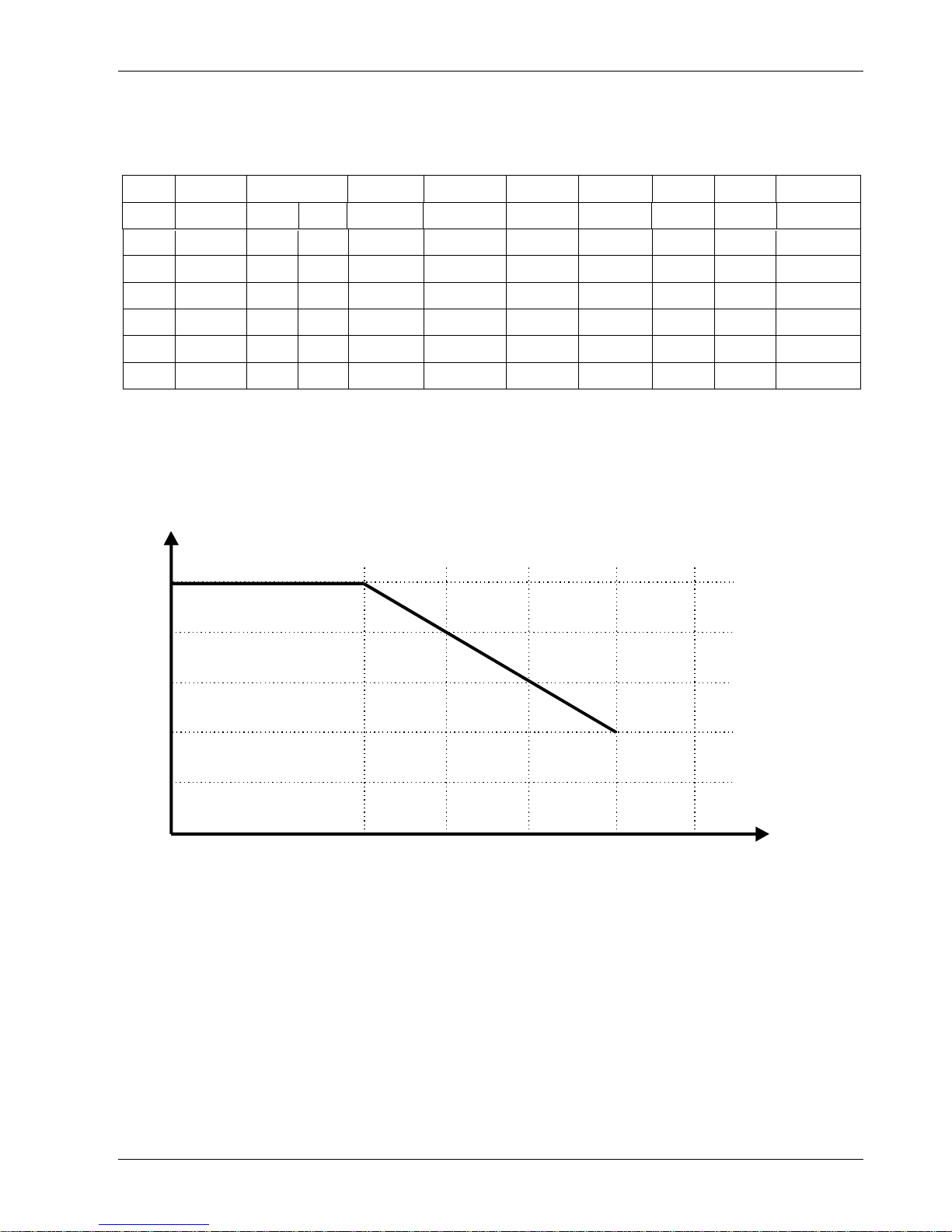
2.4 Derating curve
1
0.8
0.6
0.4
0.2
0
40 50 60 70 80
K
°
C
I = I x K
NOMMAX
Page 10

Honeywell CD3000M-3PH up to 90A User’s Manual
www.honeywell.com/imc 8
3. Ordering information
Model CD3000M 3PH
1 2 3 4 5 6 7
CD3000M-3PH
Ex:CD3000M 3PH/ 75A/
400V/ 480V/ 460V
/
SSR/ ZC/ UL
1 Nominal current of CD3000M
15A 60A
30A 75A
45A 90A
2 Operating Load Voltage (incoming voltage supply)
Specify the value of the line supply.
3 Max VOLTAGE of CD3000M
480V
600V
The voltage on the identification label must be equal or more than
operating voltage. The minimum voltage supply to the load is 24V.
4 Auxiliary Voltage
230V 200÷230V ±15%; 10VA
460V 300÷460V ±15%; 10VA
600V 600V ±15%; 10VA (on request)
5 Input
SSR 4÷30VDC
0-10V 0÷10V analog input
4-20mA 4÷20mA analog input
10K pot Potentiometer
6 Firing
ZC Zero Crossing
BF Burst firing. Specify the number on ON cycles at 50% of
power.
7 Options
COMM MODBUS protocol in RS485 is standard
EF External fuses and fuseholders
NF No fuses
CD-KP External Keypad
HB Heater Break Alarm
FAN110
Fan voltage supply 110VAC ± 15% (std 230VAC ± 15%)
14W 50/60Hz
UL UL Certification
Page 11
User’s Manual CD3000M-3PH up to 90A Honeywell
9 www.honeywell.com/imc
4. Installation and wiring information
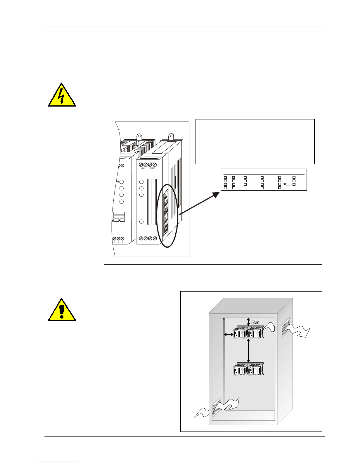
4.1 Identification of the unit
Before to install the CD3000M unit examine for damages or deficiencies. If any is
found, notify the carrier immediately. Check that the product features shown on
CD3000M cover and identification label corresponds to that ordered.
INPUTAMPS AUX. FIRING OPT.
0-10V15 60
240V
____
4-20mA25 90
440V
SC DT
SSR35 110
POT45
___
____
PA
S.S
ZC
An identification label provides all the
informations regarding the factory
settings of the unit. This label is on the
board inside the unit, as represented
4.2 Installation
CD3000M unit should be always
mounted in vertical position to
improve air cooling on heatsink.
Maintain minimum distances in
vertical and in horizontal as below
represented. Don’t install in proximity of hot
elements and near units generating
electromagnetic interferences.
A
IR OUTPUT
A
IR INP UT
15cm
2 cm
When more units are mounted inside a cubicle
provide air circulation as below represented.
Sometimes it is necessary to provide a fan to
have a better air circulation.
Page 12
Honeywell CD3000M-3PH up to 90A User’s Manual
www.honeywell.com/imc 10
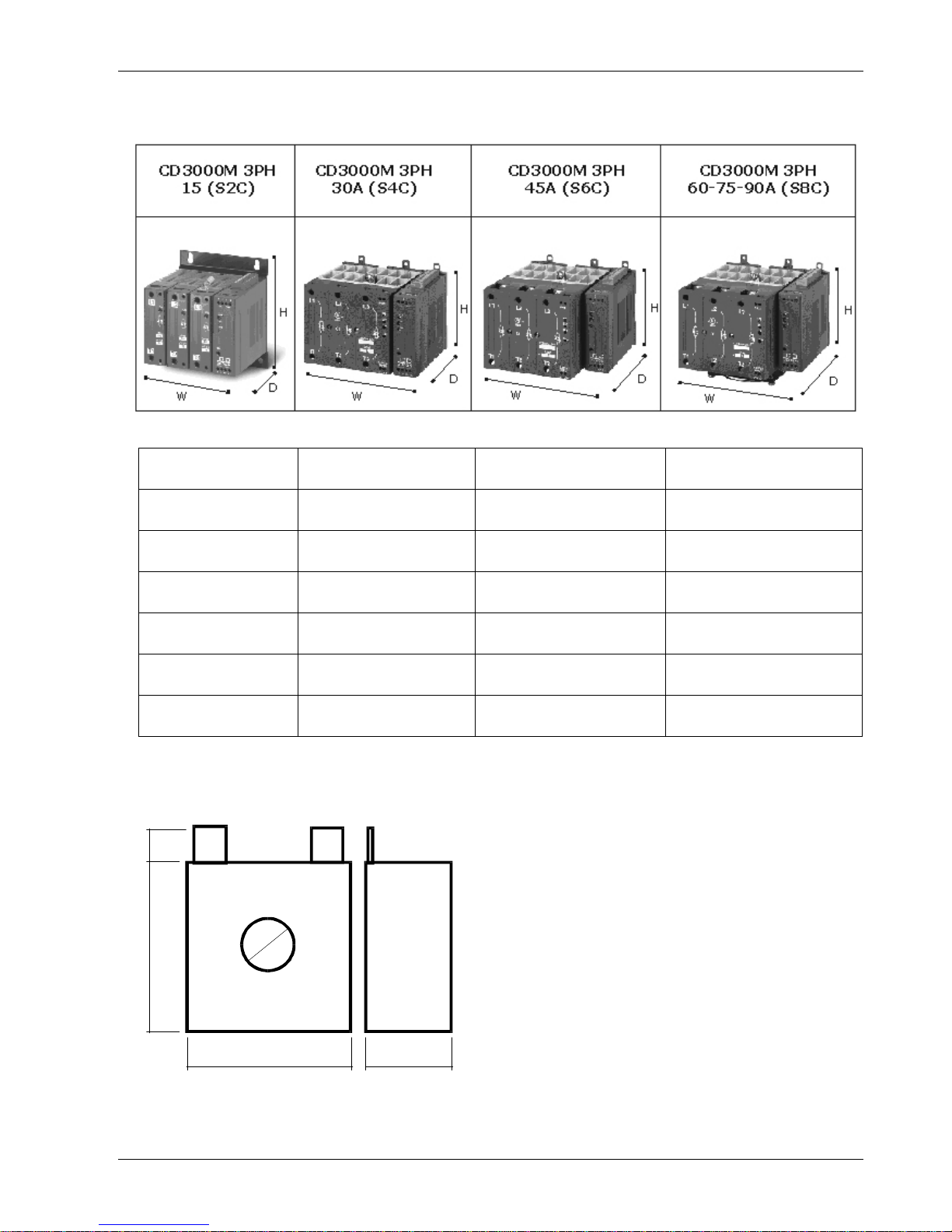
4.3 Dimensions
Size W(mm) H(mm) D(mm)
15A (S2C) 123 120 120
30A (S4C) 148 120 123
45A (S6C) 148 138 123
60A (S8C) 148 138 159
75A (S8C) 148 138 159
90A (S8C) 148 138 159
4.4 CT dimensions (Heater Break HB)
8
1
2
39
39 20
Page 13
User’s Manual CD3000M-3PH up to 90A Honeywell
11 www.honeywell.com/imc
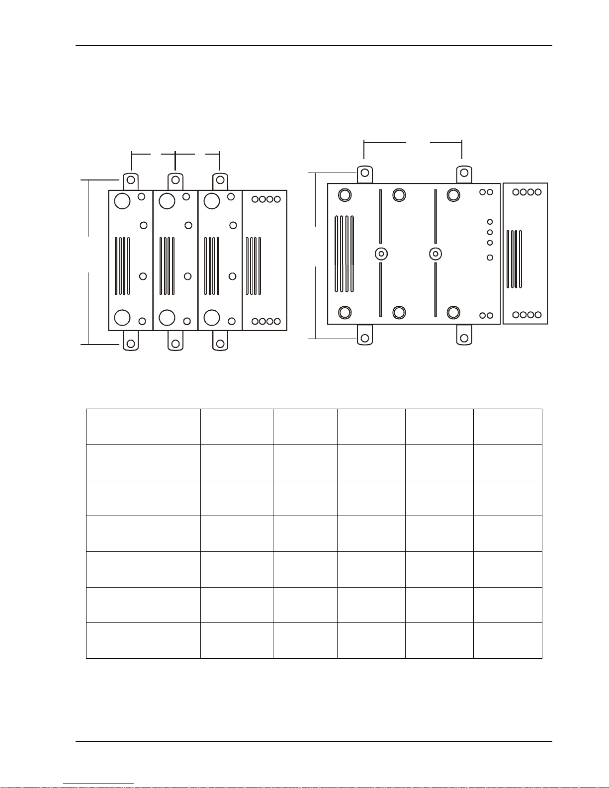
4.5 Fixing Holes
D
E
A
B C
Size A(mm) B(mm) C(mm) D(mm) E(mm)
15A (S2C) 110 30 30 - -
30A (S4C) - - - 110 65
45A (S6C) - - - 110 65
60A (S8C) - - - 110 65
75A (S8C) - - - 110 65
90A (S8C) - - - 110 65
Page 14
Honeywell CD3000M-3PH up to 90A User’s Manual
www.honeywell.com/imc 12
5. Wiring Instructions
Warning: this procedure can be done just by specialized personnel.
CD3000M unit has isolated heatsink. For safety connect the heatsink to hearth using its terminal
with hearth symbol.
CD3000M can be susceptible to airborne interferences from near equipment or from interferences
on main supply, so a number of precautions must be taken.
• Contactors coils and chokes must have in parallel a RC filter and must be supplied with a
different voltage line.
• All input/output signal must use screened bifilar wires.
• Signal input and output must not routing in same cable try and must not be parallel.
• Local regulations regarding electrical installation should be rigidly observed.
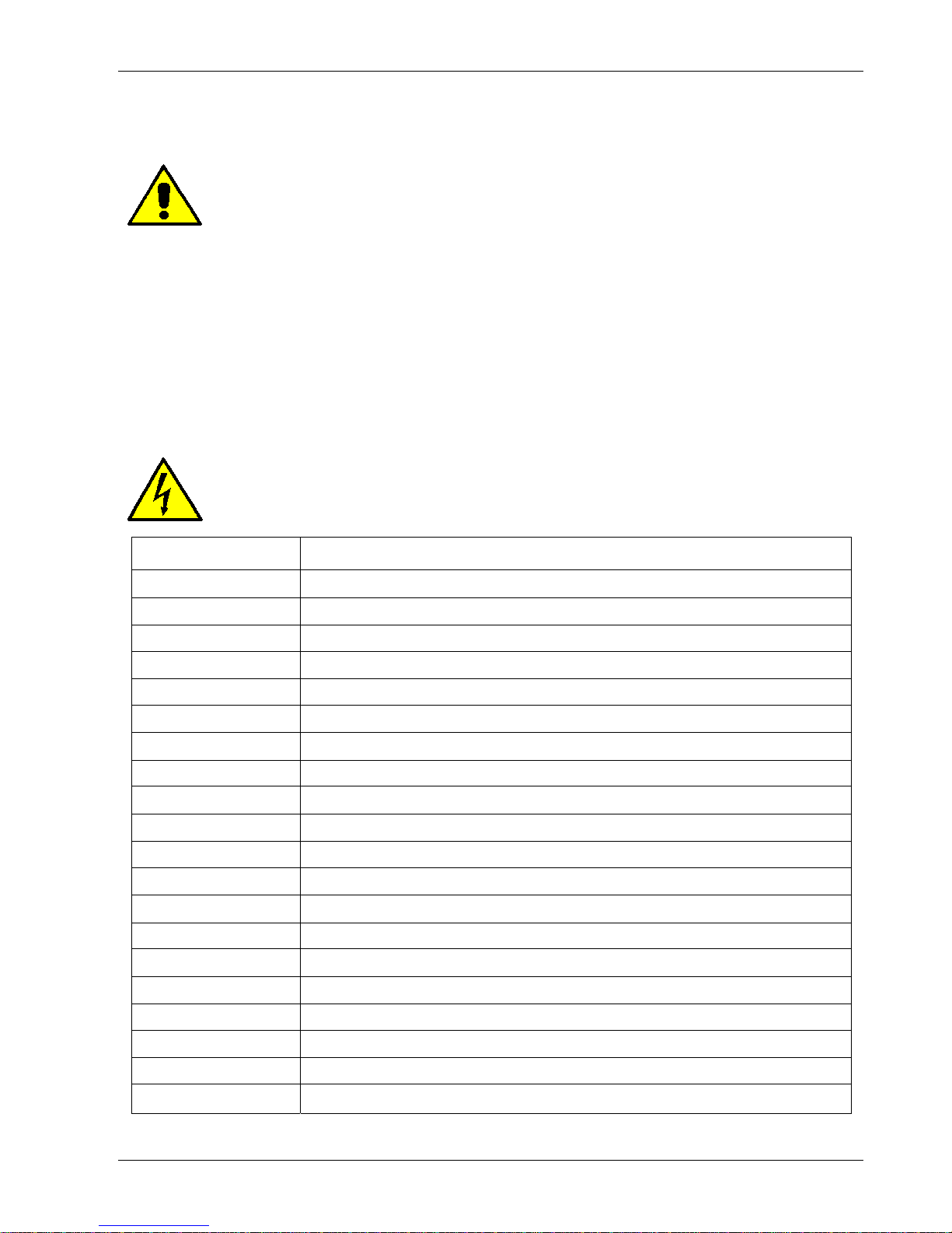
3.3.2 Auxiliary terminals
Before connect or disconnect, make sure that the power, control cables and wires are
insulated from the voltage
Terminal Description
1 - External Calibration command 24 Vdc max
2 + External Calibration command 24 Vdc max
3 Reset
4 Reset
5 + Output Command signal to CD3000 (Internal Connections)
6 - Output Command signal to CD3000 (Internal Connections)
A2+ + Input command signal 4÷20mA,0÷10V,SSR
A1- - Input command signal 4÷20mA,0÷10V,SSR
7 RS485 A
8 RS485 B
9 Output +8Vdc stabilized 1 mA MAX
10 Common relay H.B. alarm
11 NC/NO H.B. relay alarm
12 Option
13 CT input with H.B. option
14 CT input with H.B. option
15 Nc not connected
16 Auxiliary supply voltage 230-460Vac
17 Ground
18 Auxiliary supply voltage 230-460Vac
Page 15

User’s Manual CD3000M-3PH up to 90A Honeywell
13 www.honeywell.com/imc
5.1.1 Power Terminals
Before connect or disconnect, make sure that the power, control cables and wires are
insulated from the voltage
Terminal Description
L1 Line Input
T1 Load Output
L2 Line Input
T2 Load Output
L3 Line Input
T3 Load Output
Page 16

Honeywell CD3000M-3PH up to 90A User’s Manual
www.honeywell.com/imc 14
5.2 Cabling detail
Use 75°C copper (CU) conductor only, provided with the terminal type indicated below.
(Utiliser conducteur de cuivre (CU) pour 75°C seulement , avec les terminal suivants )
Current/courant
Torque/couple
Lb-in (N-m)
Wire/cable Wire terminal/terminal
15A 26.6 (3.0) 18-8
UL Listed (ZMVV)
Wire Pin Terminal
(terminal avec cosse)
30A, 45A
60A, 75A, 90A
70.8 (8.0) 18-1
UL Listed (ZMVV)
- Fork/Spade Terminal
(terminal avec cosse a
fourche)
- Copper Tube Cr. Lug
(cosse tubulaire a plage
étroite)
Page 17

User’s Manual CD3000M-3PH up to 90A Honeywell
15 www.honeywell.com/imc
Power terminals: wire details:
Current Supply Load
Cable Clable
mm
2
AWG
Screw
M
mm
2
AWG
Screw
M
15A 4 12 M5 4 12 M5
30A 6 10 M6 6 10 M6
45A 10 8 M6 10 8 M6
60A 16 6 M6 16 6 M6
75A 25 4 M6 25 4 M6
90A 35 3 M6 35 3 M6
Auxiliary connectors and earth:
Current Auxiliary Supply Earth
Cable Clable
mm
2
AWG
mm
2
AWG
Screw
M
15A 0,50 18 4 12 M4
30A 0,50 18 6 10 M5
45A 0,50 18 6 10 M5
60A 0,50 18 6 10 M5
75A 0,50 18 6 10 M5
90A 0,50 18 6 10 M5
Page 18
Honeywell CD3000M-3PH up to 90A User’s Manual
www.honeywell.com/imc 16
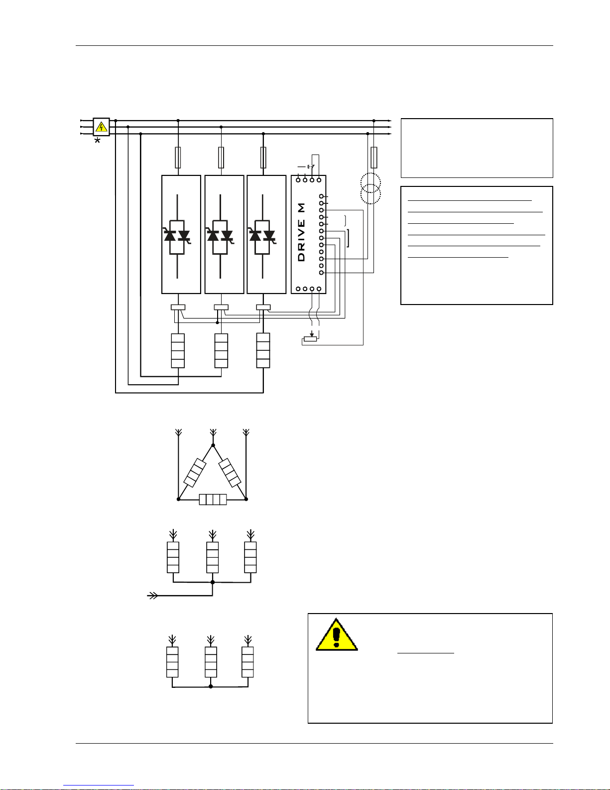
5.3 Wiring connections
5.3.1 CD3000 15-25-35-45A
POWER UNIT
Input
CT
Reset
-
+
RS485-B
1
65
7
8
9
10
11
12
13
14
15
16
17
18
2
A2+3A1-
4
RS485-A
COM
NO/NC
H.B.
Contact
10V
External
Calibration
+-
POWER UNIT
POWER UNIT
CT1
L3L2L1
CT2 CT3
T3T2T1
L2
L3
L1
L2
L3
L1
**
* The user installation must
be protect by
electromagnetic circuit
breaker or by fuse isolator
** If the Auxiliary Voltage
(written on the identification
label) is different from
Supply Voltage (to the load),
use an external transformer
as designated above.
Open Delta Load
Delta Load
Neutral
Start Load + Neutral
NOTE: IMPORTANT
To work, terminals 3-4 must be linked.
The auxiliary voltage supply of
Drive M unit
must be connected as above, and must be
syncronized with load voltage power supply (L1,
L3).
Start Load
Page 19

User’s Manual CD3000M-3PH up to 90A Honeywell
17 www.honeywell.com/imc
5.3.2 CD3000 30A
* The user installation must
be protect by
electromagnetic circuit
breaker or by fuse isolator
POWER UNIT
Input
CT
Reset
-
+
RS485-B
1
65
7
8
9
10
11
12
13
14
15
16
17
18
2
A2+3A1-
4
RS485-A
COM
NO/NC
H.B.
Contact
8V
External
Calibration
+-
CT3
L2L1
CT1 CT2
T2T1
L2
L3
L1
L2
L3
L1
**
L3
T3
** If the Auxiliary Voltage
(written on the identification
label) is different from
Supply Voltage (to the load),
use an external transformer
as designated above.
Open Delta Load
Delta Load
Neutral
NOTE: IMPORTANT
To work, terminals 3-4 must be linked.
The auxiliary voltage supply of
Drive M unit
must be connected as above, and must be
syncronized with load voltage power supply (L1,
L3).
Start Load + Neutral
Start Load
5.3.3 CD3000 45-60-75-90A
Page 20

Honeywell CD3000M-3PH up to 90A User’s Manual
www.honeywell.com/imc 18
* The user installation must
be protect by
electromagnetic circuit
breaker or by fuse isolator
POWER UNIT
Input
CT
Reset
-
+
RS485-B
1
65
7
8
9
10
11
12
13
14
15
16
17
18
2
A2+3A1-
4
RS485-A
COM
NO/NC
H.B.
Contact
8V
External
Calibration
+-
CT3
L2L1
CT1 CT2
T2T1
L2
L3
L1
FAN
220 Vac
L2
L3
L1
**
L3
T3
** If the Auxiliary Voltage
(written on the identification
label) is different from
Supply Voltage (to the load),
use an external transformer
as designated above.
Open Delta Load
Delta Load
Neutral
Start Load + Neutral
NOTE: IMPORTANT
To work, terminals 3-4 must be linked.
The auxiliary voltage supply of
Drive M unit
must be connected as above, and must be
syncronized with load voltage power supply (L1,
L3).
Start Load
Page 21

User’s Manual CD3000M-3PH up to 90A Honeywell
19 www.honeywell.com/imc
5.4 LED Status Table
LED STATUS DESCRIPTION
PW
Auxiliary supply is not connect
Auxiliary supply is connect
SC
SCR OK
SCR short circuit
HB
Laod OK
Load Fault
ON
OFF Condition(Load IS NOT Powered)
ON Condition(Load IS Powered)
= OFF
= ON
Page 22

Honeywell CD3000M-3PH up to 90A User’s Manual
www.honeywell.com/imc 20
6. START UP
Before to supply the thyristor unit:
• verify that load current equal or less than nominal;
For resistive load For inductive delta open load
I
=
V 3
P
Tot
I
=
3 V
P
Tot
• verify that there is no short circuit on load;
• verify that main voltage equal or less than nominal;
• verify that all auxiliary connections are right and syncronized to main voltage!!!;
• Fan voltage equal than nominal (230V std, 120V optional)
After which supply thyristor unit giving the maximum input signal and verify that load current is
equal or less than thyristor unit nominal current.
Warning: this procedure can be done just by specialized personnel.
The thyristor unit is delivered configured and tuned in line with customer
requirements. If it’s necessary to change on site the configuration, procede as below
specified.
Page 23

User’s Manual CD3000M-3PH up to 90A Honeywell
21 www.honeywell.com/imc
6.1 To remove the board
1 Remove plastic Cover 2 Pull the PCB
Page 24

Honeywell CD3000M-3PH up to 90A User’s Manual
www.honeywell.com/imc 22
6.2 Auxiliary supply
Warning: this procedure can be done just by specialized personnel.
To change auxiliary supply voltage sold the correct link-jumper on main PCB
230V Auxiliary supply
Main PCB
460V Auxiliary supply
J9
J10
J11
J9
J11
J10
J9
J10
J11
• If the Auxiliary Voltage (written on the identificat ion label) is different from Supply Voltage
(to the load ), use an external transformer.
• If load voltage is not included in range of 230V ±15% or 460V +15% provide an external
transformer with primary equal to load voltage and secondary 230V if your unit is setted to
230V.
Page 25

User’s Manual CD3000M-3PH up to 90A Honeywell
23 www.honeywell.com/imc
6.3 Analog input
Warning: this procedure can be done just by specialized personnel.
6.3.1 Setting Analog input
To change input type remove plastic cover and configure jumpers as represented below:
Jumpers Configuration
FRONT PCB
Input
J7 J16 J17
SSR
ABC
ABC
ABC
0÷10V
ABC
ABC
ABC
4÷20MA
ABC
ABC
ABC
Front PCB
Page 26

Honeywell CD3000M-3PH up to 90A User’s Manual
www.honeywell.com/imc 24
6.3.2 Tuning Analog input
Warning: this procedure can be done just by specialized personnel.
UNIT OFF
ST AR T TUNE
END
TUNE
Mantain Kay CAL pushed
and Switch ON
SSR input (3-30V)
is tuned
Analog input
is tuned
Wait for more than 10 sec.
from start flashing
yellow and red leds
Within 10 sec. from start
flashing yellow and red leds
push again moment ary
CAL Key
Yellow led only is
flashing, apply
0 input Signal
I.E.: 0V for 0-10V
4mA for 4-20mA
Red led only is
flashing, apply
10V for 0-10V input
or
20mA for 4-20mA input
Now press CAL Key again
Now press CAL Key again
The leds will
stop flashing
Release key
when red and yellow
led are ON
Y ello and red leds
are flashing
SSR
ANALOG
INPUT TYPE
ON
ON
ON
2sec.
S/C
S/C
S/C
H.B.
H.B.
H.B.
ON
S/C
H.B
ON
S/C
H.B
0 Signal
Max Signal
Page 27

User’s Manual CD3000M-3PH up to 90A Honeywell
25 www.honeywell.com/imc
6.4 Heater Break Alarm
Heater Break Alarm is a microprocessor based circuit to diagnose partial or total load failure and
short circuit on SCR and fuses failure.
• discrimination better than 20%;
• latching alarm plus reset;
• relay output 0.5A at 125VAC.
Minimum current 3A. If load current is below this value make two turns or more
around current transformer. H.B. circuit also diagnose fuse failure.
H.B. circuit reads load current via a current transformer 25-50/0.05 or 100/0.05 depending on
thyristor size.
6.4.1 Heater Break Alarm indication
LED STATUS DESCRIPTION
SC
SCR OK
SCR short circuit
HB
Laod OK
Load Fault
= OFF
= ON
= Flashing
The thyristor unit is supplied with a normally closed (N/C) contact.
In alarm condition and without auxiliary voltage the contact is closed (relay coil not
energized). In normal condition (no alarm) the contact is open (relay coil energized).
6.4.2 Reset
To reset Heater Break Alarm open RESET contact on terminal 3-4.
Page 28

Honeywell CD3000M-3PH up to 90A User’s Manual
www.honeywell.com/imc 26
6.4.3 HB alarm contact
Warning: this procedure can be done just by specialized personnel.
The contact of the H.B. Relay is available on auxiliary termin als.
Terminal Descriprion
10 Common relay HB alarm
11 NO/NC HB relay alarm
To change relay status remove plastic cover and configure jumpers as represented below:
STATUS RELE STATUS
MAIN PCB
J19
IN Alarm Close
Circuit not
powered
Close
CB
A
(std)
OK Open
IN Alarm Open
Circuit not
powered
Open
CB
A
OK Close
Page 29

User’s Manual CD3000M-3PH up to 90A Honeywell
27 www.honeywell.com/imc
Main PCB
Page 30

Honeywell CD3000M-3PH up to 90A User’s Manual
www.honeywell.com/imc 28
6.4.4Calibration
This procedure it’s necessary to give set point to Heater Break. CD3000M reads the load current
many times and when the value is the same for three times takes it as set point.
Calibration procedure:
• verify that connections are correct;
• supply the thyristor unit;
• push “CAL” button on front of CD3000M unit,
or supply with 24Vdc terminals 1-2 or send command via RS485;
• the thyristor unit goes in conduction state to measure load current;
• all LEDS are ON, this means that calibration procedure is active;
• after one minute LEDS for H.B. and S/C switch off (calibration procedure is done);
• the thyristor unit is ready to work.
Page 31

User’s Manual CD3000M-3PH up to 90A Honeywell
29 www.honeywell.com/imc
6.4.5 Digital input Command
POWER UNIT
Reset
1
65
7
8
9
10
11
12
13
14
15
16
17
18
2
A2+3A1-
4
COM
NO/NC
H.B.
Contact
POWER UNIT
Reset
1
65
7
8
9
10
11
12
13
14
15
16
17
18
2
A2+3A1-
4
COM
NO/NC
H.B.
Contact
6.4.6 RS485 Command
RS485-A
RS485-B
POWER UNIT
Reset
1
65
7
8
9
10
11
12
13
14
15
16
17
18
2
A2+3A1-
4
COM
NO/NC
H.B.
Contact
POWER UNIT
Reset
1
65
7
8
9
10
11
12
13
14
15
16
17
18
2
A2+3A1-
4
COM
NO/NC
H.B.
Contact
If load current decreases for partial or total load failure (sensitivity 20% standard adjustable v ia
RS485) the yellow LED becomes ON and alarm relay changes status.
If CD3000M is still in conduction with no input signal (LED green OFF) it means that there is a
short circuit on thyristors and red LED (SC) becomes ON.
The diagnostic is active only when the switching period is longer than 60ms (3 main
voltage cycle).
If the load has been changed calibration procedure must be done again.
Page 32

Honeywell CD3000M-3PH up to 90A User’s Manual
www.honeywell.com/imc 30
7. Thyristor firing mode
SSR from co n t roller
LOAD VOLTAGE (V)
VOLTAGE SUP PLY (V)
ZERO CROSSING
7.1 Zero Crossing (ZC)
ZC firing mode is used with Logic Output
from temperature controllers and the
Thyristor operates like a contactor. The Cycle
time is performed by temperature controller.
ZC minimizes interferences because the
Thyristor unit switches ON-OFF at zero
voltage.
VOLTAGE SUPPLY (V)
20%
50%
70%
100%
7.2 Burst Firing (BF)
This firing performed in Digital mode in
Honeywell Thyristor unit gives a lot of
advantages because switches Thyristor at
zero voltage crossing without EMC
interferences. Analog input is necessary for
BF and can be decided how many complete
cycles we want at 50% of power demand.
This value can be implemented from 1 to 255
complete cycles doing the firing less or more
fast. When 1 is setted the firing name
becomes Single Cycle (see above).
Page 33

User’s Manual CD3000M-3PH up to 90A Honeywell
31 www.honeywell.com/imc
7.3 Configurator
To configure CD3000M unit, you can download the free software and the Configurator Manual from
our web site www.honeywell.com/imc.
To configure the unit you can use the standard communication on terminals 7-8 or use a
programming cable.
Page 34

Honeywell CD3000M-3PH up to 90A User’s Manual
www.honeywell.com/imc 32
To connect the programming cable to the thyristor unit, remove cover as in picture.
PROG.
CONN.
Once removed the cover, put a side of cable in prog connector(K10) and the other side in the PC
RS232(9PIN) serial port.
Page 35

User’s Manual CD3000M-3PH up to 90A Honeywell
33 www.honeywell.com/imc
8. Fuse and fuseholder for UL certification unit
8.1 Fuse and Fuse Code
The thyristor unit must be protected by fuses against short circuit selecting the proper I²t that
must be lower than thyristor one. The same caution must be taken if Circuit Breaker is used.
Remember that is very difficult to protect the thyristor if this choise is done.
WARNING!! USE SEMICONDUCTOR FUSES ONLY WITH proper I
2
t
Bussmann Div
Cooper (UK) Ltd
(200 kA
RMS
Symmetrical A.I.C.)
Ferraz Shawmut SA
(200 kA
RMS
Symmetrical A.I.C.)
Ratings / tailles Ratings / tailles
Sizes
Fuse Mod. No.
/fusible modéle
Current
(A
RMS
)
I
2
t
(A
2
sec)
V ac
Fuse Mod. No.
/fusible modéle
Current
(A
RMS
)
I
2
t
(A
2
sec)
Vac
Qty
15A FWC 16A10F 16 150 600 660 Grb 10-16 16 145 660 3
30A FWC 40A14F 40 980 600 CP URC 14x51/40 40 700 660 3
45A FWP 50A14F 50 1800 700 CP URC 14x51/50 50 1500 660 3
60A FWP 80A22F 80 5100 700 CP URD 22x58/80 80 3800 660 3
75A - - - - - - - - CP URQ 27x60/100 100 3210 660 3
90A - - - - - - - - CP URQ 27x60/125 125 6970 660 3
High speed fuses are only used for the thyristor protection and can not be used to
protect the installation.
The user installation must be protect by electromagnetic circuit breaker or by fuse
isolator.
The warranty of thyristor is null if no proper fuses are used. See tab above.
Page 36

Honeywell CD3000M-3PH up to 90A User’s Manual
www.honeywell.com/imc 34
8.2 FuseHolder size
15A 30-45A
60 mm
80 mm
17mm
110 mm
77 mm
26mm
60 A 75-90A
35mm
77 mm
125 mm
150 mm
107 mm
37mm
70 mm
9 mm
9 mm
6mm
19 mm
Page 37

User’s Manual CD3000M-3PH up to 90A Honeywell
35 www.honeywell.com/imc
9. Fuse and fuseholder for CE mark unit
9.1 Fuse and Fuse Code
The thyristor unit must be protected by fuses against short circuit selecting the proper I²t that
must be lower than thyristor one. The same caution must be taken if Circuit Breaker is used.
Remember that is very difficult to protect the thyristor if this choise is done.
WARNING!! USE SEMICONDUCTOR FUSES ONLY WITH proper I
2
t
CD3000 SERIE I²T (max)
(A² sec.)
Size and current Fuse and
Fuseholder
CODE
Fuse
CODE
15 600 10,3X38 / 16A FFH1038/16A FU1038/16A
30 980 14X15 / 40A FFH1451/40A FU1451/40A
45 1800 14X15 / 50A FFH1451/50A FU1451/50A
60 5100 22x58 / 80A FFH2258/80A FU2258/80A
75 10000 22X58 / 100A FFH2258/100A FU2258/100A
90 15000 27X60 / 125A FFH2760/125A FU2760/125A
High speed fuses are only used for the thyristor protection and can not be used to
protect the installation.
The user installation must be protect by electromagnetic circuit breaker or by fuse
isolator.
The warranty of thyristor is null if no proper fuses are used. See tab above.
Page 38

Honeywell CD3000M-3PH up to 90A User’s Manual
www.honeywell.com/imc 36
9.2 FuseHolder size
15A 30-45A
60 mm
80 mm
17mm
110 mm
77 mm
26mm
60-75A 90A
35mm
77 mm
125 mm
150 mm
107 mm
37mm
70 mm
9 mm
9 mm
6mm
19 mm
Page 39

User’s Manual CD3000M-3PH up to 90A Honeywell
37 www.honeywell.com/imc
10.Modbus communication
The CD3000M is equipped with two-wire RS485-compatible serial communications, by
which means communication may occur between the Controller and a master device
(e.g. a computer or terminal).
10.1 Physical requirements
10.1.1 Character Transmission
Data format is fixed to be one start bit, eight data bits, one stop bit, baud rate 9600 and the parity
none.
10.2 ModBus RTU protocol
The standard RS485 Communications uses the industry standard MODBUS RTU protocol.
The following restrictions are imposed:
• Baud rates is fixed to 9600 Baud only.
• Support for multi-parameter Write operations is limited to support of the Multi-
Word Write Function (Number 16) but it permits the writing of only one
parameter per message.
The following MODBUS functions are supported:
Function Function Number
Read Holding Registers (Read n Word) 03
Preset Multiple Registers (Write n Word) 16
The Controller will identify itself in response to a Read Holding Registers message which enquires
the values of word parameters 121 and 122 (see Table 4-2).
MODBUS Function 17 (Report Slave ID) is not supported.
10.2.1Message Formats
The first character of every message is the Controller address, in the range 1 - 255 and 0 for
broadcast messages.
The second character is always the Function Number.
The contents of the remainder of the message depends upon this Function Number.
In most cases the Controller is required to reply to the message by echoing the address and
Function Number.
Broadcast messages are supported at address 0 (to which the CD3000M responds by
taking some action without sending back any reply).
Data is transmitted as eight-bit binary bytes with one start bit, one stop bit and parity checking set
to none. A message is terminated simply by a delay of more than three character lengths at the
Baud rate used(in this case 9600 baud); any character received after such a delay is considered to
be the potential address at the start of a new message.
Page 40

Honeywell CD3000M-3PH up to 90A User’s Manual
www.honeywell.com/imc 38
Since only the RTU form of the protocol is supported, each message is followed by a two-byte
CRC 16 (a 16-bit cyclic redundancy checksum).
This checksum is calculated in accordance with a formula which involves recursive division of the
data by a polynomial, with the input to each division being the remainder of the results of the
previous division.
The dividing polynomial is
2
16
+ 215 + 22 + 1(Hex 18005)
but this is modified in two ways:
• because the bit order is reversed, the binary pattern is also reversed, making the most
significant bit (MSB) the right-most bit;
• because only the remainder is of interest, the right-most (most significant) bit can be
discarded.
Thus, the polynomial has the value Hex A001.
10.2.2 Bit’s order
Normal bit order
Most significant bit Least significant bit
Most significant byte Least significant Byte
Reversed bit order
Least significant bit Most significant bit
Least significant Byte Most significant byte
N.B.: Reversed order apples, so CRC16 return Reversed bit order
Page 41

User’s Manual CD3000M-3PH up to 90A Honeywell
39 www.honeywell.com/imc
START
Setting FFFF (Hex) To CR
CR= CRC error check data (1 wo rd)
I = Digits of calculation characters
in command message
J = Check on the number of times
of CR calculation
Settin g 1 to I
Settin g 1 to J
CR is shifted by
1 bit to right
Added 1t o J
Added 1 to I
END
After shifting CR by 1 bit to righ t, A001(Hex) and exclusive logical sum
(XOR) are executed for setting the result in CR
Bit at right and of CR is 1?
NO
NO
NO
YES
YES
YES
Eight times of calculation
is completed?
J>8
Calculation of all charactersis completed?
I>All charac ters numbers
Exclusive lo gic a l Sum (XO R ) is e x ecu ted on one charac ter (1 byte) at I
charactor of CR and de signat ed messa ge , an d results are set t o CR.
Page 42

Honeywell CD3000M-3PH up to 90A User’s Manual
www.honeywell.com/imc 40
10.2.3 C Language CRC 16 Example
static short CRC16 (unsigned char *p_first,unsigned char *p_last)
{
unsigned int crc=0xffff;
short j;
for (;p_first<=p_last;p_first++)
{
crc ^= *p_first;
for(j=8;j>0;j--)
{
if(crc & 0x0001)
{
crc = crc >> 1;
crc ^= 0xA001;
}
else
{
crc = crc >> 1;
}
}
}
return (crc);
}
10.2.4 Read Holding Registers (Read n Words) – Function 03
The message sent to the Controller to obtain the value of one or more registers comprises the
following eight bytes:
Addr. unit Func. Address
1° word
N° of Word CRC 16
3
3Hex
HI LO HI LO HI LO
The normal reply will echo the first two characters of the message received follow ed by a singlebyte data byte count (which will not includ e itself or the CRC).
For this message, the count value equals the number of parameter v a lues read multiplied by two.
Following the byte count, the specified number of parameter values are transmitted, followed by
the CRC16 bytes:
Addr. unit Func. Cont. 1° Value Last Value CRC 16
3
3Hex
HI LO HI LO HI LO
Page 43

User’s Manual CD3000M-3PH up to 90A Honeywell
41 www.honeywell.com/imc
10.2.5 Preset Multiple Registers (Write n Words) - Function 16
This is an eleven-byte message. only one parameter may be written for each received message.
The usual pre-amble is followed by the address of the parameter to be written, a two-byte word
count (always set to 1), a single-byte byte count (always set to 2), the value to be written and
the CRC16 bytes:
Addr. unit Func. Addr of
1° Word
N° of Word Cont. Valore CRC 16
16
10Hex
HI LO 0 1 2 HI LO HI LO
The Controller normally responds with the following eight-bit reply:
Addr. unit Func. N° of Word N° Word CRC 16
16
10Hex
HI LO 0 1 HI LO
10.2.6 Error and Exception Responses
If a received message contains a corrupted character (parity check failure, framing error etc.) or if
the CRC16 check fails, or if the received message is otherwise syntact ically flawed (e.g. byte count
or word count is incorrect), the thyristor will ignore that message.
If the received message is syntactically correct but nonetheless contains an illegal value, the
thyristor will send a five-byte exception response as follows :
Addr. unit Func. N.Exception CRC 16
HI LO
The Function Number byte contains the function number contained in the message which caused
the error, with its top bit set (i.e. Function 3 becomes 0x83) and the Exception Number is on of
the following codes:
Code Name Cause
1 ILLEGAL FUNCTION Function number out of range
2 ILLEGAL DATA ADDRES Parameter ID out of range or not supported
3 ILLEGAL DATA VALUE Attempt to write invalid data/required action not
executed
NOTE: Writing a parameter value equal to its current value is a valid transaction; this will
not cause an error response.
Page 44

Honeywell CD3000M-3PH up to 90A User’s Manual
www.honeywell.com/imc 42
10.3 Word parameters
Parameter N. Notes
Heater nominal current 1 Read only
Set-point HB 2 Read /write
Status Table (shown in Tab 2.1.2) 3 Read only
Comand Table (shown in Tab 2.1.3) 4 Read /write
Output Power (0 – FFH) 5
Read - (Write if BIT1in Command table i = 1)
(0->0% - FF->100%)
Power Adjust (0 – FFH) 6
Read -- (Write if BIT1in Command table i =
1)
(0->0% - FF->100%)*
10.3.1 Heater nominal current Parameter 1
Operation: Read
Meaning:
It correspond at one value in points (0-255,0-FF Hex).
It represents average current value flowing into thyristors.
Value depends on current transformer ratio that is different from one size to the other one (see
below table)
Nominal current
(A)
Zero (0 , 0 Hex)
(A)
Max ( 255 , ff Hex)
(A)
3,5 0 3,5
15 0 25
25 0 25
35 0 50
45 0 50
60 0 100
90 0 100
110 0 100
Page 45

User’s Manual CD3000M-3PH up to 90A Honeywell
43 www.honeywell.com/imc
10.3.2 Set-point HB Parameter 2
Operations: Read/Write
Meaning:
It correspond at one value in points (0-255, o-FF Hex). It’s the set of current value below which
HB alarm occurs.
This value is the load current minus % value of parameter 124H. This value depend on nominal
current of transformer that change in function of thyristor nominal current as described in below
tab.
Nominal current
(A)
Zero (0 , 0 Hex)
(A)
Max ( 255 , ff Hex)
(A)
3,5 0 3,5
15 0 25
25 0 25
35 0 50
45 0 50
60 0 100
90 0 100
110 0 100
10.3.3 Status Table Parameter 3
Operations: Read
Meaning:
It’s a tab in bit that represent the “Status” of thyristor unit
10.3.4 Comand Table Parameter 4
Operations: Read/Write
Meaning:
It’s a tab in bit for remote commands via RS485 (see tab)
Page 46

Honeywell CD3000M-3PH up to 90A User’s Manual
www.honeywell.com/imc 44
10.3.5 Output Power Parameter 5
Command from controller
Operations: Read
Meaning:
It rapresent a value in points (0-255, 0-FF Hex) and it’s the power demand in % of controller.
Example:
0% = 0 0 (Hex)
50% = 128 80 (Hex)
100% = 255 FF (Hex)
Command via RS485
Operations : Read/Write
Meaning:
It’s a value in points (0-255, 0-FF Hex)
It’s power set point setted in thirst buffer
Example:
0% = 0 0 (Hex)
50% = 128 80 (Hex)
100% = 255 FF (Hex)
10.3.6 Power adjust Parameter 6
Operations: Read/Write
Meaning:
Its’ a value in points (0-255, 0-FF Hex)
Its’ a scaling factor of power demand
Example 1:
0% = 0
50% = 128
100% = 255
Example 2:
• Output Power :100
Power Limit :100
-> Power real : 100
• Output Power :100
Power Limit :50
-> Power real : 50
• Output Power :80
Power Limit :50
-> Power real : 40
100
Power Adjust = 100 %
Power Adjust = 80%
Power Adjust = 40%
80
60
40
20
0
4020 60 10080
Inpu t %
OUT %
Page 47

User’s Manual CD3000M-3PH up to 90A Honeywell
45 www.honeywell.com/imc
10.3.7 Status Table
Bit Meaning Notes
0 Short circuit on SCR Read only
1 Load Failure Read only
2 On-Off Read only
3 HB Calibration in progress Read only 0=Normal - 1=Calibration
10.3.7.1 Short circuit on SCR Bit 0
Operations: Read
Meaning:
Its’ a status but that represents the short circuit on thyristor
0 = OK
1 = Short circuit
10.3.7.2 Load Failure Bit 1
Operations: Read
Meaning:
It’s a bit that represent partial or total load failure.
0 = OK
1 = Load failure
10.3.7.3 On-Off Bit 2
Operations: Read
Meaning:
It’s a bit that represent when input signal is ON
0 = Input signal OFF
1 = Input signal ON
10.3.7.4 HB Calibration in progress Bit 3
Operations: Read
Meaning:
It’s a bit status that represent “calibration in progress”
0 = No calibration
1 = Calibration in progress
Page 48

Honeywell CD3000M-3PH up to 90A User’s Manual
www.honeywell.com/imc 46
10.3.8 Command Table
Bit Meaning Notes
0 HB Calibration
Read /write 0=Off - 1=ACTVATE Calibration
( normal mode set to 0)
1 Firing command Read /write 0=from terminal - 1=from RS485
2 On-Off Read /write 0=Off - 1=On
3 RESET HB
Read /write 0=Off - 1=RESET
( normal mode set to 0)
N.B.: When unit is switch off all command parameter are set to 0
10.3.8.1 HB Calibration Bit 0
Operations: Read / Write
Meaning:
It’s a bit that starts the HB calibration procedure
When this bit is zero start the calibration procedure and reset itself automatically at the end.
10.3.8.2 Firing command Bit 1
Operations: Read / Write
Meaning:
It’s a command bit used to switch from analog external command to command via RS485
0 = Command of analog input
1 = Command of RS485 input
10.3.8.3 On-Off Bit 2
Operations: Read / Write
Meaning:
Its’ an enable bit to switch ON-OFF the power.
0 = Power disabled
1 = Power enabled
10.3.8.4 HB RESET Bit 3
Operations: Read / Write
Meaning:
It’s a command bit to reset HB alarm.
This parameter has to be at 0 to have the alarm working properly
0 = Reset disabled
1 = Reset enabled
Page 49

User’s Manual CD3000M-3PH up to 90A Honeywell
47 www.honeywell.com/imc
10.4 Thyristor unit Configuration
Parameter N. Notes
Password 123 Write
Delay trigger 124L Read /write
% HB 124H Read /write
Firing type 125L Read /write
Soft start time 125H Read /write
N° burst 126L Read /write
Delay time HB 126H Read /write
Max power for SSR Input 127L Read /write
Cycle time 127H Read /write
N° of half period for Delayed triggering 128L Read /write (Mantenere a 1)
128H Read /write
10.4.1 Password Parameter 123
Operations: Write
Meaning:
If properly setted give the access to configuration
10.4.2 Delay triggering Parameter 124L
Operations: Read/Write
Meaning:
It’s correspond to a value in points (0-50, 0-32 Hex)
Each step is 0,1msec. Range is 0-5msec.
This parameter is the delay of firig in first half period with respect zero voltage crossing.
10.4.3 % HB Parameter 124H
Operations: Read/Write
Meaning:
It’s correspond to a value in point (0-255, 0-ff Hex)
This parameter is the value in % that decrease the load current to establish the HB current set
point
Example:
Load current = 10A
Parameter 124H = 20% 51 Dec 33 Hex
Parameter 2 will be setted at 8A
Page 50

Honeywell CD3000M-3PH up to 90A User’s Manual
www.honeywell.com/imc 48
10.4.4 Firing type Parameter 125L
Operations: Read/Write
Meaning:
Selection table of firing modes.
Value Type Option
H L
0 1 Zero Crossing 0 2 Single Cycle 0 3 Burst 1 1 Zero Crossing Soft Start
1 2 Single Cycle 1 3 Burst Soft Start
2 1 Zero Crossino Delay trigger
2 2 Single Cycle
2 3 Burst Delay triggering
2 4 Phase angle Soft start
10.4.5 Soft start time Parameter 125H
Operations: Read/Write
Meaning :
Time
Soft Start Time
Par 125H x 5msec
OUT
It’s correspond to a value in points (0 – 255, 0 – FF Hex).
Each step is 5msec .
The unit start in phase angle mode with a ramp starting from
zero up to full voltage in a presetted and Adjustable time.
The time is setted by this parameter.
Value of this parameter must be less than cycle time.
For burst firing:
Value of this parameter must be less than:
50Hz -> 20msec x Number of cycles (Parameter 126L).
60Hz -> 16,6msec x Number of cycles (Parameter 126L).
Page 51

User’s Manual CD3000M-3PH up to 90A Honeywell
49 www.honeywell.com/imc
10.4.6 N° burst Parameter 126L
Operations: Read/Write
Meaning:
It’s a value in point (0 – 255, 0 – FF Hex).
In burst firing mode it rapresents the number of cycles at 50% power demand
10.4.7 Delay time HB Parameter 126H
Operations: Read/Write
Meaning:
It’s a value in point (0 – 255, 0 – FF Hex).
Each step is 50msec.
It represent a delay to have HB alarm active
When is used soft start this time must be longer than soft start time.
Par126H x 50msec > Par125H x 5msec
When zero crossing firing is used must be less than cycle time
Par126H x 50msec > Par127H x 50msec
10.4.8 Max power for SSR Input Parameter 127L
Operations: Read/Write
Meaning:
It’s a value in points (0 – 255, 0 – FF Hex).
When SSR input is used it represent the value of the power (%) when is in ON status.
It’s the power % when firing command is given on RS485 (1).
Example:
0% = 0 0 (Hex)
50% = 128 80 (Hex)
100% = 255 FF (Hex)
Page 52

Honeywell CD3000M-3PH up to 90A User’s Manual
www.honeywell.com/imc 50
10.4.9 Cycle time Parameter 127H
Operations: Read/Write
Meaning:
It’s a value in points (0 – 255, 0 – FF Hex).
Each step is 50msec .
Cycle Time
Time
20%
ON OFF
50%
70%
100%
When single cycle (SC) and burst firing (BF) is used must be setted at 240 (FO Hex)
When SSR input is used set at 240 (FO Hex)
When is used zero crossing (ZC) represents the cycle time
(ON time + OFF time, default 60(3C Hex) )
10.4.10 Number of half periods for DT firing Parameter 128L
Operations: Read/Write
Meaning:
Must be setted at 1.
Page 53

User’s Manual CD3000M-3PH up to 90A Honeywell
51 www.honeywell.com/imc
10.5 Address configuration
1
ON OFF
2
3
4
5
6
7
8
To Configure communication address remove cover and set
the dip-switch as below specified.
10.5.1 Address table
ID 8 7 6 5 4 3 2 1 ID 8 7 6 5 4 3 2 1
1 - - - - - - - X 26 - - - X X - X 2 - - - - - - X - 27 - - - X X - X X
3 - - - - - - X X 28 - - - X X X - 4 - - - - - X - - 29 - - - X X X - X
5 - - - - - X - X 30 - - - X X X X 6 - - - - - X X - 31 - - - X X X X X
7 - - - - - X X X 32 - - X - - - - 8 - - - - X - - - 33 - - X - - - - X
9 - - - - X - - X 34 - - X - - - X 10 - - - - X - X - 35 - - X - - - X X
11 - - - - X - X X 36 - - X - - X - 12 - - - - X X - - 37 - - X - - X - X
13 - - - - X X - X 38 - - X - - X X 14 - - - - X X X - 39 - - X - - X X X
15 - - - - X X X X 40 - - X - X - - 16 - - - X - - - - 41 - - X - X - - X
17 - - - X - - - X 42 - - X - X - X 18 - - - X - - X - 43 - - X - X - X X
19 - - - X - - X X 44 - - X - X X - 20 - - - X - X - - 45 - - X - X X - X
21 - - - X - X - X 46 - - X - X X X 22 - - - X - X X - 47 - - X - X X X X
23 - - - X - X X X 48 - - X X - - - 24 - - - X X - - - 49 - - X X - - - X
25 - - - X X - - X 50 - - X X - - X -
Page 54

Honeywell CD3000M-3PH up to 90A User’s Manual
www.honeywell.com/imc 52
ID 8 7 6 5 4 3 2 1 ID 8 7 6 5 4 3 2 1
51 - - X X - - X X 101 - X X - - X - X
52 - - X X - X - - 102 - X X - - X X 53 - - X X - X - X 103 - X X - - X X X
54 - - X X - X X - 104 - X X - X - - 55 - - X X - X X X 105 - X X - X - - X
56 - - X X X - - - 106 - X X - X - X 57 - - X X X - - X 107 - X X - X - X X
58 - - X X X - X - 108 - X X - X X - 59 - - X X X - X X 109 - X X - X X - X
60 - - X X X X - - 110 - X X - X X X 61 - - X X X X - X 111 - X X - X X X X
62 - - X X X X X - 112 - X X X - - - 63 - - X X X X X X 113 - X X X - - - X
64 - X - - - - - - 114 - X X X - - X 65 - X - - - - - X 115 - X X X - - X X
66 - X - - - - X - 116 - X X X - X - 67 - X - - - - X X 117 - X X X - X - X
68 - X - - - X - - 118 - X X X - X X 69 - X - - - X - X 119 - X X X - X X X
70 - X - - - X X - 120 - X X X X - - 71 - X - - - X X X 121 - X X X X - - X
72 - X - - X - - - 122 - X X X X - X 73 - X - - X - - X 123 - X X X X - X X
74 - X - - X - X - 124 - X X X X X - 75 - X - - X - X X 125 - X X X X X - X
76 - X - - X X - - 126 - X X X X X X 77 - X - - X X - X 127 - X X X X X X X
78 - X - - X X X - 128 X - - - - - - 79 - X - - X X X X 129 X - - - - - - X
80 - X - X - - - - 130 X - - - - - X 81 - X - X - - - X 131 X - - - - - X X
82 - X - X - - X - 132 X - - - - X - 83 - X - X - - X X 133 X - - - - X - X
84 - X - X - X - - 134 X - - - - X X 85 - X - X - X - X 135 X - - - - X X X
86 - X - X - X X - 136 X - - - X - - 87 - X - X - X X X 137 X - - - X - - X
88 - X - X X - - - 138 X - - - X - X 89 - X - X X - - X 139 X - - - X - X X
90 - X - X X - X - 140 X - - - X X - 91 - X - X X - X X 141 X - - - X X - X
92 - X - X X X - - 142 X - - - X X X 93 - X - X X X - X 143 X - - - X X X X
94 - X - X X X X - 144 X - - X - - - 95 - X - X X X X X 145 X - - X - - - X
96 - X X - - - - - 146 X - - X - - X 97 - X X - - - - X 147 X - - X - - X X
98 - X X - - - X - 148 X - - X - X - 99 - X X - - - X X 149 X - - X - X - X
100 - X X - - X - - 150 X - - X - X X -
Page 55

User’s Manual CD3000M-3PH up to 90A Honeywell
53 www.honeywell.com/imc
ID 8 7 6 5 4 3 2 1 ID 8 7 6 5 4 3 2 1
151 X - - X - X X X 201 X X - - X - - X
152 X - - X X - - - 202 X X - - X - X 153 X - - X X - - X 203 X X - - X - X X
154 X - - X X - X - 204 X X - - X X - 155 X - - X X - X X 205 X X - - X X - X
156 X - - X X X - - 206 X X - - X X X 157 X - - X X X - X 207 X X - - X X X X
158 X - - X X X X - 208 X X - X - - - 159 X - - X X X X X 209 X X - X - - - X
160 X - X - - - - - 210 X X - X - - X 161 X - X - - - - X 211 X X - X - - X X
162 X - X - - - X - 212 X X - X - X - 163 X - X - - - X X 213 X X - X - X - X
164 X - X - - X - - 214 X X - X - X X 165 X - X - - X - X 215 X X - X - X X X
166 X - X - - X X - 216 X X - X X - - 167 X - X - - X X X 217 X X - X X - - X
168 X - X - X - - - 218 X X - X X - X 169 X - X - X - - X 219 X X - X X - X X
170 X - X - X - X - 220 X X - X X X - 171 X - X - X - X X 221 X X - X X X - X
172 X - X - X X - - 222 X X - X X X X 173 X - X - X X - X 223 X X - X X X X X
174 X - X - X X X - 224 X X X - - - - 175 X - X - X X X X 225 X X X - - - - X
176 X - X X - - - - 226 X X X - - - X 177 X - X X - - - X 227 X X X - - - X X
178 X - X X - - X - 228 X X X - - X - 179 X - X X - - X X 229 X X X - - X - X
180 X - X X - X - - 230 X X X - - X X 181 X - X X - X - X 231 X X X - - X X X
182 X - X X - X X - 232 X X X - X - - 183 X - X X - X X X 233 X X X - X - - X
184 X - X X X - - - 234 X X X - X - X 185 X - X X X - - X 235 X X X - X - X X
186 X - X X X - X - 236 X X X - X X - 187 X - X X X - X X 237 X X X - X X - X
188 X - X X X X - - 238 X X X - X X X 189 X - X X X X - X 239 X X X - X X X X
190 X - X X X X X - 240 X X X X - - - 191 X - X X X X X X 241 X X X X - - - X
192 X X - - - - - - 242 X X X X - - X 193 X X - - - - - X 243 X X X X - - X X
194 X X - - - - X - 244 X X X X - X - 195 X X - - - - X X 245 X X X X - X - X
196 X X - - - X - - 246 X X X X - X X 197 X X - - - X - X 247 X X X X - X X X
198 X X - - - X X - 248 X X X X X - - 199 X X - - - X X X 249 X X X X X - - X
200 X X - - X - - - 250 X X X X X - X 251 X X X X X - X X
X = ON 252 X X X X X X
- = OFF 253 X X X X X X X
254 X X X X X X X
255 X X X X X X X X
Page 56

Honeywell CD3000M-3PH up to 90A User’s Manual
www.honeywell.com/imc 54
11. Maintenance
11.1 Trouble Shooting
Small problems sometimes can be solved locally with the help of the below tab of t rouble shootin g.
If you don’t succeed, contact us or your nearest distributor.
Symptom Indication on
front unit
Possible reasons of the symptom Actions
Green LED is
always light
off.
- No voltage auxiliary power
supply to terminals 1-3 (see
wiring diagram).
- Give auxiliary voltage supply
to terminals 1-3.
Green LED
(PW) light on
and green LED
(ON) in light
off condition.
- No input signal.
- Reversed polarities of input
signal.
- Reset contact in open condition
(see wiring diagram).
- Provide to give input signal.
- Reverse the input signal
polarity.
- Make link on reset terminals.
Thyristor unit
doesn’t go in
conduction with
input signal.
Green LED
(PW) in light
on condition
and green LED
(ON) in light on
condition.
- Fuse failure.
- Load failure.
- Load connection interruption.
- Thyristor faulty and always in
open circuit.
- With HB option the yellow led
(HB) in light on condition.
- Substitute the fuse.
- Repair the load.
- Provide to repair the wiring.
- Substitute the faulty thyristor.
- Check the load.
Load current
flows also with
no input signal.
Green LED
(ON) always in
light off
condition.
- Short circuit on thyristor. If there
is HB circuit the red LED (SC) is
light on.
- Substitute the thyristor.
Check that load is not in short
circuit.
Current flows at
nominal value
but yellow LED
(HB) in light on
condition.
Yellow HB in
light on
condition.
- HB circuit not tuned.
- Current transformers not
properly wired (if are external to
CD3000).
- Push CAL button in front unit
to start HB calibration
procedure.
- Control current transformers
wiring and Push CAL button in
front unit to start HB
calibration procedure.
Red LED (SC) is
lighted also if
current is at
nominal value.
Red LED in
light on
condition.
- HB circuit not properly tuned. - Push CAL button in front unit
to start HB calibration
procedure.
Thyristor unit
doesn’t work
properly.
- Wrong input signal selection.
- Wrong input signal calibration
(out of range).
- Auxiliary voltage supply out of
limits.
- Control input signal setting.
- Repeat input calibration
procedure.
- Verify the auxiliary voltage
supply.
Page 57

User’s Manual CD3000M-3PH up to 90A Honeywell
55 www.honeywell.com/imc
11.2 Repairing procedure
• Phone to us.
• Explain to Service Engineer the problem because sometimes it can be solved with a phone call.
• If this is not possible ship the unit to us or to your distributor.
• Write a fault description and give the name of your personnel to which refer.
• Use a rugged packaging to ship the unit.
11.3 Fans
The thyristor unit with forced ventilation uses fans that rotate permanently when the unit is
supplied. In case of accidental fan failure, there is an over heating temperature on heatsink. In this
case to give protection to thyristor there is a thermal switch properly setted. The function of this
switch is to open the input signal until the h eatsink temperature falls below the setted value. This
means that also with input signal in ON condition the unit is switched OFF and the system can not
work at full power. For these reason is important to control periodically the fan status checking
that is rotating.
11.4 Servicing
In order to have correct cooling, the user must clean the heatsink and the protective grill of fan.
The frequence of this servicing depends on environmenta l pollution.
Check periodically also if the screw for the power cables and safety earth are tightened correctly
11.5 Warranty conditions
We gives a 12 months warranty to its products. The warranty is limited to repairing and parts
substitution in our factory and does exclude products not properly used and fuses.
Warranty does not includes products with serial numbers deleted. The faulty product should be
shipped to us at your cost and our Service will evaluate if product is un d er warranty terms.
Substituted parts remains our property.
Page 58

Honeywell CD3000M-3PH up to 90A User’s Manual
www.honeywell.com/imc 56
Sales and Service
For application assistance, current specifications, pricing, or name of the nearest Authorized Distributor, contact one of
the offices below.
Warranty/Remedy
Honeywell warrants goods of its manufacture as being free of defective materials and faulty work-manship. Contact your
local sales office of warranty information. If warranted goods are returned to Honeywell during the period of coverage,
Honeywell will repair of replace without charge those items it finds defective. The foregoing is Buyer’s sole remedy
and is in lieu of all other warranties, expressed or implied, including those of merchantability and fitness for
a particular purpose. Specifications may change without notice. The information we supply is believed to be accurate
and reliable as of printing. However, we assume no responsibility for its use. While we provide application assistance
personally, through our literature and the Honeywell website, it is up to the customer to determine the suitability of the
product in the application.
ASIA PACIFIC
Control Products
Asia Pacific Headquarters
Phone: +(65) 6355-2828
Fax: +(65) 6445-3033
Australia
Honeywell Limited
Phone: +(61) 2-9370-4500
FAX: +(61) 2-9370-4525
Toll Free 1300-36-39-36
Toll Free Fax: 1300-36-04-70
China – PRC - Beijing
Honeywell China Inc.
Phone: +(86-10) 8458-3280
Fax: +(86-10) 8458-3102
China – PRC - Shanghai
Honeywell China Inc.
Phone: (86-21) 6237-0237
Fax: (86-21) 6237-1237
China - Hong Kong S.A.R.
Honeywell Ltd.
Phone: +(852) 2953-6412
Fax: +(852) 2953-6767
China – PRC - Chengdu
Honeywell China Inc.
Phone: +(86-28) 6786-348
Fax: +(86-28) 6787-061
China – PRC - Guangzhou
Honeywell China Inc.
Phone: +(86-20) 3879-1169
Fax: +(86-20) 3879-1269
China – PRC - Shenzhen
Honeywell China Inc.
Phone: +(86) 755-518-1226
Fax: +(86) 755-518-1221
Indonesia
Honeywell Indonesia Pte Ltd.
Phone: +(62) 21-535-8833
FAX: +(62) 21-5367 1008
India
TATA Honeywell Ltd.
Phone: +(91) 20 687
0445/0446
Fax: +(91) 20 681 2243/ 687
5992
Japan
Honeywell Inc
Phone: +(81) 3 5440 1425
Fax: +(81) 3 5440 1368
South Korea
Honeywell Korea Co Ltd
Phone: +(822) 799-6167
Fax: +(822) 792-9013
Malaysia
Honeywell Engineering
Sdn Bhd
Phone: +(60-3) 79584988
Fax: +(60-3) 7958-8922
New Zealand
Honeywell Limited
Phone: +(64-9) 623-5050
Fax: +(64-9) 623-5060
Toll Free (0800) 202-088
Philippines
Honeywell Systems
(Philippines) Inc.
Phone: +(63-2) 636-1661
/1662
Fax: +(63-2) 638-4013
Singapore
Honeywell South East
Asia
Phone: +(65) 6355-2828
Fax: +(65) 6445-3033
Thailand
Honeywell Systems
(Thailand) Ltd.
Phone: +(662) 693-3099
FAX: +(662) 693-3085
Taiwan R.O.C.
Honeywell Taiwan Ltd.
Phone: +(886-2) 22451000
FAX: +(886-2) 22453242
EUROPE
Austria
Honeywell Austria GmbH
Phone: +43 (316)400123
FAX: +43 (316)40017
Belgium
Honeywell SA/NV
Phone:
+31(0)205656999
FAX: +31(0)165330746
Bulgaria
Honeywell EOOD
Phone: +(359) 2 79 40
27
FAX: +(359) 2 79 40 90
Czech Republic
Honeywell spol. s.r.o.
Phone: +420-543245014
FAX: +420-54324-5011
Denmark
Honeywell A/S
Phone: +(45) 39 55 55 55
FAX: +(45) 39 55 55 58
Finland
Honeywell OY
Phone: +358 (3) 2727625
FAX: +358 (3) 2728600
France
Honeywell SA
Phone: +33 (0)1 60198075
FAX: +33 (0)1 60198201
Germany
Honeywell AG
Phone: +49 (69)8064336
FAX: +49 (69)806497336
Hungary
Honeywell Kft.
Phone: +36-1-451 4335
FAX: +36-1-451 4343
Italy
Honeywell S.p.A.
Phone: +39 02 9214 6503
FAX: +39 0292146377
The Netherlands
Honeywell B.V.
Phone: +31(0)205656999
FAX: +31(0)165330746
Norway
Honeywell A/S
Phone: (45) 39 55 55 55
Poland
Honeywell Sp. zo.o
Phone: +48-22-6060900
FAX: +48-22-6060901
Portugal
Honeywell Portugal Lda
Phone: +351 21 424 5000
FAX: +351 21 424 50 99
Romania
Honeywell Bucharest
Phone: 40212110076
FAX: +40 (40212103375)
Commonwealth of
Independent States (CIS)
Z.A.O. Honeywell
Phone: +(7 095) 796 98 36
FAX: +(7 095) 796 98 93
Slovak Republic
Honeywell s.r.o.
Phone: +421-2-58247 410
FAX: +421-2-58247 415
Spain
Honeywell S.A.
Phone: +34 (0)91313 61 00
FAX: +34 (0)91313 61 30
Sweden
Honeywell AB
Phone: +(46) 8 775 55 00
FAX: +(46) 8 775 56 00
Switzerland
Honeywell AG
Phone: +41 18552448
FAX: +(41) 1 855 24 45
Turkey
Honeywell Turkey A.S.
Phone: +90 216 575 6600
FAX: +90 216 575 6637
United Kingdom
Honeywell Control Systems
Ltd
Phone: +(44) 1698 481730
FAX: +(44) 1698 481276
MIDDLE EAST
Abu Dhabi U A E
Middle East Headquarters
Honeywell Middle East Ltd
Phone: +971 2 4041220
FAX: +971 2 4432536
Sultanate of Oman
Honeywell & Co Oman LLC
Phone: +968 701397
FAX +968 787351
Egypt
Honeywell Egypt Ltd
Phone: +202 4514460 /1/
2/ 3/ 4/ 5/ 6
FAX : +2024514467
Saudia Arabia
Honeywell Turki Arabia
Limited
Phone: +966-3-341-0140
Fax: +966-3-341-0216
Kuwait
Honeywell Kuwait KSC
Phone: +965 2421327
AFRICA
Mediterranean & African
Distributors
Honeywell SpA
Phone: +39 (02) 250 10
604
FAX: +39 (02) 250 10 659
South Africa (Republic of)
Honeywell Southern Africa
Honeywell S.A. Pty. Ltd
Phone: +27 11 6958000
FAX +27 118051504
NORTH AMERICA
Canada
Honeywell LTD
Phone: 1-800-737-3360
FAX: 1-800-565-4130
USA
Honeywell
Control Products,
International Headquarters
Phone: 1-800-537-6945
1-815-235-6847
FAX: 1-815-235-6545
E-mail:
info.sc@honeywell.com
LATIN AMERICA
Argentina
Honeywell S.A.I.C.
Phone: +(54-11) 4383-3637
FAX: +(54-11) 4325-6470
Brazil
Honeywell do Brasil & Cia
Phone: +(55-11) 7266-1900
FAX: +(55-11) 7266-1905
Chile
Honeywell Chile, S.A.
Phone: +(56-2) 233-0688
FAX: +(56-2) 231-6679
Mexico
Honeywell S.A. de C.V.
Phone: +(52) 55 5259-1966
FAX: +(52) 55 5570-2985
Puerto Rico
Honeywell Inc.
Phone: +(809) 792-7075
FAX: +(809) 792-0053
Trinidad
Honeywell Inc
Phone: +(868) 624-3964
FAX: +(868) 624-3969
Venezuela
Honeywell CA
Phone: +(58-2) 238-0211
FAX: +(58-2) 238-3391
 Loading...