

Page 1
Put Bar Code Here
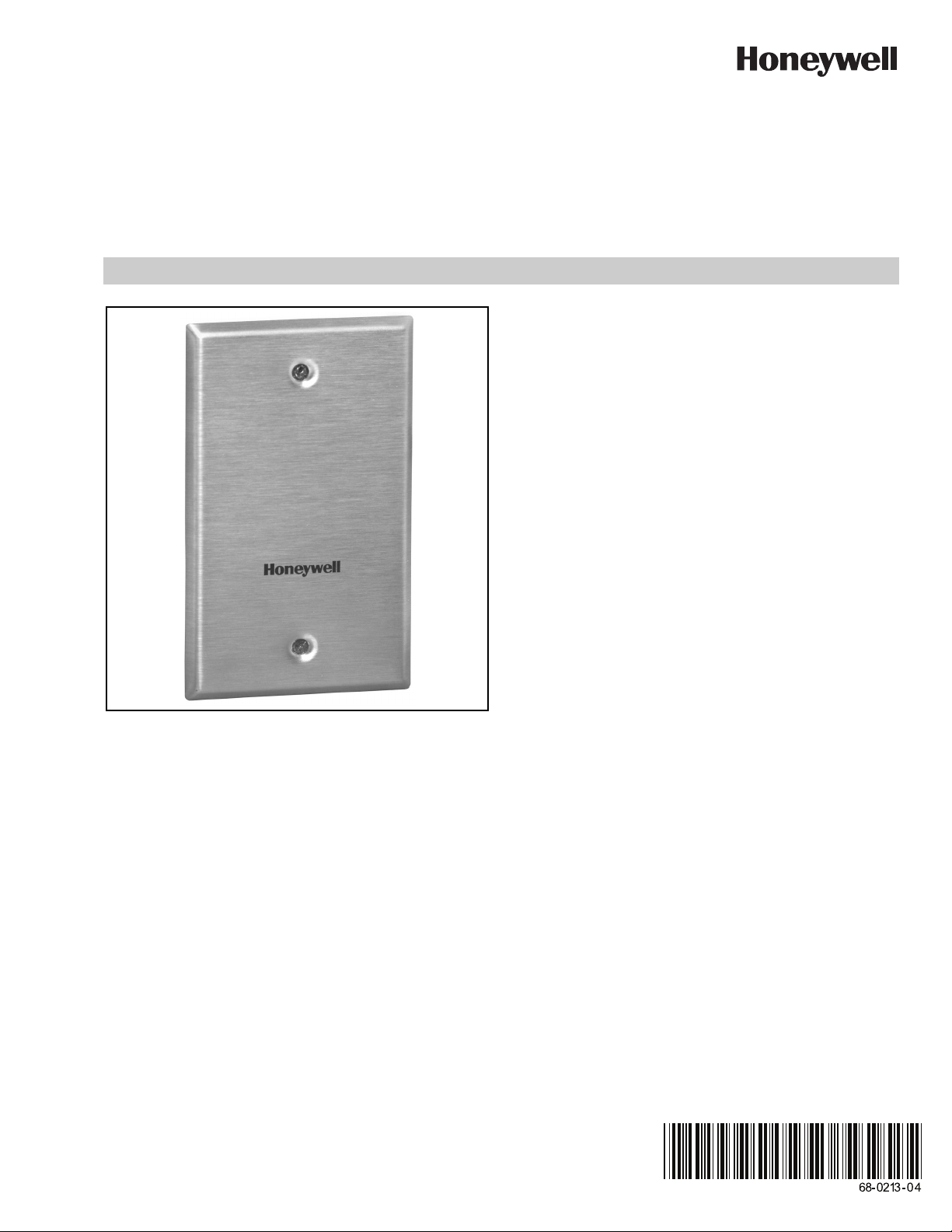
C7772A, F, G
Wallplate Temperature Sensor
FEATURES
• Low profile when mounted on industry standard utility
conduit box.
• Rugged, brushed stainless steel wallplate.
• Integral foam pad isolates wallplate sensor from conduit
box.
• Insulated screw terminals ensure reliable field wiring
connection.
• Models available with a variety of resistive temperature
sensor elements.
PRODUCT DATA
APPLICATION
The C7772A series of Wallplate Temperature Sensors are
designed to be used with the Excel 5000 family and other
Honeywell controllers. The C7772F Series is designed to be
used with the TB7600, TB7300, and TB7200 Series
communicating thermostats and other controllers that require
a 10K ohm NTC Type II sensor. The C7772G is designed to
be used with WEBs-AX I/O modules and other controllers that
require a 10K ohm NTC Type III sensor. The C7772 sensors
provide a resistive output signal proportional to sensed room
or space temperature. The C7772 is well suited for low-profile
wall-mounted applications where durability and tamper-proof
construction is desired, such as schools, prisons and
institutions.
Page 2

C7772A, F, G WALLPLATE TEMPERATURE SENSOR
CAUTION
4-1/2
(114)
3-5/16
(84)
2-3/4 (70)
5/16 (8)
M16295A
SPECIFICATIONS
Models: See Table 1.
Dimensions: See Fig. 1.
Temperature Ratings:
Operating: 45°F to 99°F (7°C to 37°C).
Shipping: -40°F to 150°F (-40°C to 65°C).
Long-term temperature sensor drift:
(for 20K ohm sensors only)
Maximum sensor drift is nominally +/-0.13°F after 5 years of
operation, no appreciable drift thereafter. No calibration of the
device is possible. Long term drift calibration/maintenance
through controller software is typically not necessary.
Humidity Ratings: 5 to 95% rh, non-condensing.
Approvals:
National Electrical Code (NEC) Class II.
INSTALLATION
When Installing this Product...
1. Read these instructions carefully. Failure to follow them
could damage the product or cause a hazardous
condition.
2. Check the ratings given in the instructions and on the
product to make sure the product is suitable for your
application.
3. Installer must be a trained, experienced service
technician.
4. After installation is complete, check out product
operation as provided in these instructions.
5. Follow local codes for installation and application.
IMPORTANT
All wiring must agree with applicable codes,
ordinances and regulations.
Electrical Shock or Equipment Damage Hazard.
Can shock individuals or short equipment
circuitry.
Disconnect all power supplies before installation.
Location
The C7772 Wallplate Temperature Sensor should be located
where it can sample an average air temperature. Avoid
locations where air stratification can cause sensing errors.
The sensor mounts directly on a 2 in. x 4 in. conduit box with
the screws provided.
ORDERING INFORMATION
When purchasing replacement and modernization products from your TRADELINE® wholesaler or distributor, refer to the
TRADELINE® Catalog or price sheets for complete ordering number.
If you have additional questions, need further information, or would like to comment on our products or services, please write or
phone:
1. Your local Honeywell Automation and Control Products Sales Office (check white pages of your phone directory).
2. Honeywell Customer Care
3. http://customer.honeywell.com or http://customer.honeywell.ca
International Sales and Service Offices in all principal cities of the world. Manufacturing in Belgium, Canada, China, Czech
Republic, Germany, Hungary, Italy, Mexico, Netherlands, United Kingdom, and United States.
68-0213-04 2
Fig. 1. C7772 Dimensions in in. (mm).
1885 Douglas Drive North
Minneapolis, Minnesota 55422-4386
Page 3

C7772A, F, G WALLPLATE TEMPERATURE SENSOR
CAUTION
CAUTION
STANDARD UTILITY
CONDUIT BOX
CONNECTOR
LOCKNUT
AND
CONDUIT
TO APPROPRIATE
SYSTEM
COMPONENTS
BLANK
FACEPLATE
M16296
Table 1. C7772 Models.
Model Sensor Type Nominal Resistance
Resistance-Temperature
Curve Type
Lead Wire
Color
C7772A 20K NTC Thermistor 20,000 ohms at 77°F (25°C) Non-linear Negative TCR Green/Blue
C7772F 10K Ohm NTC Type II Thermistor 10,000 ohms @ 77°F (25°C) Non-linear Negative TCR Green/White
C7772G 10K Ohm NTC Type III Thermistor 10,000 ohms @ 77°F (25°C) Non-linear Negative TCR White/White
NOTE: TCR = temperature coefficient of resistance.
Mounting
To mount on conduit box (see Fig. 2):
1. Remove the appropriate knockout on the standard utility
conduit box for the application.
2. Make wiring connections to the system components.
IMPORTANT
Level only for appearance. The sensor functions
normally even when not level.
3. Use the No. 6 screws provided to mount the wallplate to
the conduit box.
1. Do not route temperature sensor wiring with
building power wiring, next to control contactors,
near light dimming circuits, electric motors or
welding equipment.
2. Avoid poor wiring connections.
3. Do not mount sensor in an incorrect environment.
Connect the low voltage wiring from the controller terminals to
the sensor screw terminals and tighten. See Fig. 2.
Wiring
Electrical Shock or Equipment Damage Hazard.
Can shock individuals or short equipment
circuitry.
Disconnect all power supplies before installation.
Erratic System Operation Hazard.
Failure to follow proper wiring practices can introduce
disruptive electrical interference (noise).
Keep wiring at least one foot away from large inductive
loads such as motors, line starters, lighting ballasts,
and large power distribution panels.
Shielded cable is required in installations where these
guidelines cannot be met.
Ground shield only to grounded controller case.
IMPORTANT
• Temperature sensor wiring can be sized from
16 to 20 AWG depending on the application.
• The maximum length of wire from a device to the
wallplate sensor is 300 ft (91m).
NOTE: Erratic temperature readings from a sensor can be
caused by the wiring practices described below.
These must be avoided to assure proper operation:
Fig. 2. Mounting, wiring for C7772.
OPERATION
The C7772 Wallplate Temperature Sensor provides a resistive
output signal proportional to the sensed room temperature.
3 68-0213—04
Page 4

C7772A, F, G WALLPLATE TEMPERATURE SENSOR
CHECKOUT
The C7772 Wallplate Temperature Sensor is immediately
operational after wiring connections are made. Use an
accurate thermometer of ±1°F (0.5°C) to measure the
temperature at the sensor location. To verify sensor accuracy,
use an ohmmeter to measure the resistance across the
sensor wires and use Table 2 to check the accuracy of the
specific model.
Table 2. Typical Resistance of Sensor Models.
Typical Resistance (in ohms)
C7772A C7772F C7772G
At 41°F (5°C) 54,200 25,392 23,467
At 50°F (10°C) 41,758 19,901 18,789
At 59°F (15°C) 32,427 15,712 15,137
At 68°F (20°C) 25,370 12,493 12,268
At 77°F (25°C) 20,000 10,000 10,000
At 86°F (30°C) 15,856 8,057 8,196
At 95°F (35°C) 12,654 6,531 6,754
Automation and Control Solutions
Honeywell International Inc.
1985 Douglas Drive North
Golden Valley, MN 55422
customer.honeywell.com
® U.S. Registered Trademark
© 2012 Honeywell International Inc.
68-0213—04 L.L. Rev. 01-2012
Printed in United States
 Loading...