

Page 1
® U.S. Registered Trademark
Copyright © 2004 Honeywell International Inc. • All Rights Reserved
INSTALLATION INSTRUCTIONS
62-0215
C7772A,B,C,D
Wallplate Temperature Sensors
APPLICATION
The C7772A,B,C,D Wallplate Temperature Sensors
provide a resistive output signal proportional to sensed
room or space temperature. The sensors are well suited
for low profile wall mounted applications where durability
and tamperproof construction is desired, such as
schools, prisons and institutions.
The C7772A Wallplate Temperature Sensors are
designed to be used with the Excel 5000 family, XL10,
XL15, T7350, and other Honeywell controllers.
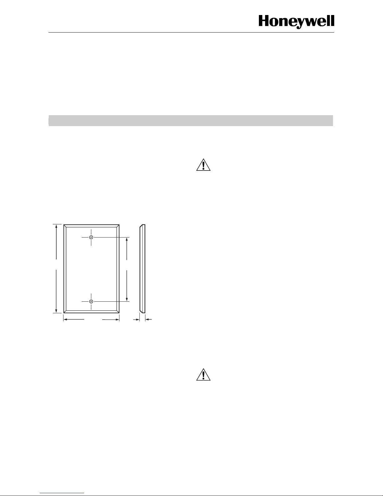
Fig. 1. C7772 Dimensions in in. (mm).
INSTALLATION
When Installing this Product...
1. Read these instructions carefully. Failure to follow
them could damage the product or cause a
hazardous condition.
2. Check the ratings given in the instructions and on
the product to make sure the product is suitable for
your application.
3. Installer must be a trained, experienced service
technician.
4. After installation is complete, check out product
operation as provided in these instructions.
5. Follow local codes for installation and application.
IMPORTANT
All wiring must agree with applicable codes,
ordinances and regulations.
CAUTION
Electrical Shock or Equipment Damage
Hazard.
Can shock individuals or short equipment
circuitry.
Disconnect all power supplies before installation.
Location
The sensor should be located where it can sample an
average air temperature. Avoid locations where air
stratification can cause sensing errors. The sensor
mounts directly on a 2 in. x 4 in. conduit box with the
screws provided.
Mounting
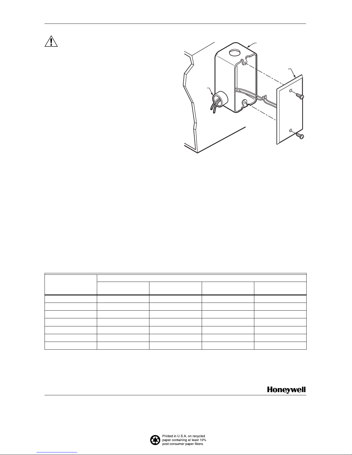
To mount on conduit box (see Fig. 2):
1. Remove the appropriate knockout on the standard
utility conduit box for the application.
2. Make wiring connections to the system
components.
IMPORTANT
Level only for appearance. The sensor
functions normally even when not level.
3. Use the No. 6 screws provided to mount the wallplate to the conduit box.
Wiring
CAUTION
Electrical Shock or Equipment Damage
Hazard.
Can shock individuals or short equipment
circuitry.
Disconnect all power supplies before installation.
4-1/2
(114)
3-5/16
(84)
2-3/4 (70)
5/16 (8)
M16295
A
Page 2
62-0215 B.B. 11-04 www.honeywell.com
C7772A,B,C,D WALLPLATE TEMPERATURE SENSORS
Automation and Control Solutions
Honeywell International Inc. Honeywell Limited-Honeywell Limitée
1985 Douglas Drive North 35 Dynamic Drive
Golden Valley, MN 55422 Scarborough, Ontario
M1V 4Z9
CAUTION
Erratic System Operation Hazard.
Failure to follow proper wiring practices can
introduce disruptive electrical interference
(noise).
Keep wiring at least one foot away from large
inductive loads such as motors, line starters,
lighting ballasts, and large power distribution
panels.
Shielded cable is required in installations where
these guidelines cannot be met.
Ground shield only to grounded controller case.
IMPORTANT
• Temperature sensor wiring can be sized from
16 to 20 AWG depending on the application.
• The maximum length of wire from a device to
the wallplate sensor is 300 ft (91m).
NOTE: Erratic temperature readings from a sensor can
be caused by the wiring practices described
below. These must be avoided to assure proper
operation:
1. Do not route temperature sensor wiring with
building power wiring, next to control
contactors, near light dimming circuits,
electric motors or welding equipment.
2. Avoid poor wiring connections.
3. Do not mount sensor in an incorrect
environment.
Connect the low voltage wiring from the controller
terminals to the sensor wires using wirenut connectors
(not provided). See Fig. 2.
Fig. 2. Mounting, wiring for C7772.
OPERATION
The sensor provides a resistive output signal proportional
to the sensed room temperature.
CHECKOUT
The sensor is immediately operational after wiring
connections are made. Use an accurate thermometer of
±1°F (0.5°C) to measure the temperature at the sensor
location. To verify sensor accuracy, use an ohmmeter to
measure the resistance across the sensor wires and use
Table 1 to check the accuracy of the specific model.
Table 1. Typical Resistance of Sensor Models.
S
TANDARD UTILIT
Y
CONDU
IT B
OX
CO
NNECT
OR
LOCKNUT
CONDUIT
TO APPROPRIATE
SYS
TEM
COMPO
NENT
S
FACEPLAT
E
M162
96
Typical Resistance (in ohms)
C7772A
(20K ohm NTC)
C7772B
(PT1000)
C7772C
(PT100)
C7772D
(PT3000)
At 41°F (5°C) 54,200 1020 102 3310
At 50°F (10°C) 41,758 1039 103.9 3353
At 59°F (15°C) 32,427 1059 105.9 3397
At 68°F (20°C) 25,370 1078 107.8 3440
At 77°F (25°C) 20,000 1097 109.7 3484
At 86°F (30°C) 15,856 1117 111.7 3527
At 95°F (35°C) 12,654 1137 113.7 3571
By using this Honeywell literature, you agree that Honeywell will have no liability
for any damages arising out of your use or modification to, the literature. You will
defend and indemnify Honeywell, its affiliates and subsidiaries, from and against
any liability, cost, or damages, including attorneys’ fees, arising out of, or
resulting from, any modification to the literature by you.
 Loading...