

Page 1
63-2615-07
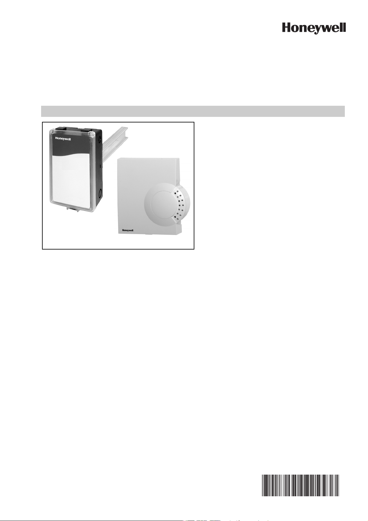
C7632A,B
C7632A
C7632B
Sensor and Controller
CARBON DIOXIDE SENSOR
SPECIFICATIONS
Models: C7632 Sensor and Controller. A stand-alone car-
bon dioxide (CO
put.
C7632A: Wall mount model.
C7632B: Duct mount model.
Dimensions:
C7632A: See Fig. 1.
C7632B: See Fig. 2.
Ambient Ratings:
Temperature:
Operating: +32°F to +122°F (0°C to +50°C).
Storage: -4°F to +158°F (-20°C to +70°C).
Relative Humidity (non-condensing): 0 to 95 percent.
PRODUCT DATA
) sensor with one 0-10 Vdc analog out-
2
APPLICATION
The C7632 Sensor and Controller is a stand-alone carbon
dioxide (CO
necessity with heating ventilation and air conditioning
(HVAC) controllers. The C7632 measures the CO
concentration in the ventilated space or duct. The C7632 is
used in HVAC systems to control the amount of fresh
outdoor air supplied to maintain acceptable levels of CO
the space.
) sensor for use in determining ventilation
2
2
in
2
FEATURES
• Non-Dispersion-Infrared (NDIR) technology used to
measure carbon dioxide gas.
• Special plated sensor provides long-term calibration
stability.
• Device provides voltage output based on CO
• Used for CO
• Automatic Background Calibration (ABC) algorithm
based on long-term evaluation reduces required
typical zero-drift check maintenance.
• Fixed 0 to 10 Vdc from 0 to 2000 ppm. No
adjustments are necessary.
• Compatible with Honeywell Excel 10, 15, 5000, and
any controller requiring 0-10 Vdc input.
based ventilation control.
2
levels.
2
Automatic Background Calibration (ABC) default: On.
Electrical Ratings:
Power Supply: 24 Vac ±20%, 50/60 Hz (Class 2).
Maximum Power Consumption:
Average: 1W.
Peak: 2W.
Peak Current (at 20 ms): 300 mA.
Linear Analog Output: 0-10 Vdc.
Mounting:
C7632A: Vertical surface with standard single-gang junction
box.
C7632B: Sheet metal duct with a sampling tube.
CO
Pressure Dependence: 1.6% change in reading per
2
1 kPa deviation from 100 kPa.
Output: Analog: 0-10 Vdc, 0-2000 ppm (fixed).
Sensor Performance Ratings:
Response Time: 1 min.
Carbon Dioxide Sensor:
Operation: Non-dispersive infrared (NDIR).
Sampling: Diffusion.
Range: 0 to 2000 ppm (fixed).
Annual Drift: ±10 ppm (nominal).
Accuracy: ±(30 ppm+2%) at normal temperature/pres-
sure.
Calibrated at the factory.
Uses automatic background calibration. No calibration
required for the life of the product.
Meets CEC Title 24 requirement of ±75ppm accuracy at
600ppm and 1000ppm ambient levels.
For proper CO2 operation, install only in spaces that see
at least 4 hours of continuous unoccupied time per
week.
Page 2
C7632A,B SENSOR AND CONTROLLER
CAUTION
CAUTION
CAUTION
2-11/16 (68)
1-1/16
(27)3-7/8 (99)
M19794
3-3/8
(86)
4-1/8
(104)
3-5/16 (84)
1-13/16
(46)
1-5/8
(41)
5-5/8
(142)
8 (203)
M19795
Wiring Connections:
C7632A: Terminal block.
C7632B: 20-gauge cable with three 6 in. leadwires.
Approvals:
CE.
C7632B: Flammability Rating, UL94-5V.
C7632A: NEMA1.
C7632B: NEMA3.
Fig. 1. C7632A dimensions in in. (mm).
IMPORTANT
All wiring must agree with applicable codes,
ordinances and regulations.
Health Hazard.
Improper use can create dangerous situations.
Use in application for sensing carbon dioxide only.
For life-safety applications, this device can function
only as a secondary or lesser device.
Electrical Shock or Equipment Damage Hazard.
Can shock individuals or short equipment
circuitry.
Disconnect power supply before installation.
Equipment Damage Hazard.
Electrostatic discharge can short equipment
circuitry.
Ensure that you are properly grounded before
handling the unit.
C7632A Cover Removal/ Replacement
The cover of the C7632A is fixed by a latch on the underside
of the unit.
C7632A Cover Removal (see Fig. 3)
Fig. 2. C7632B dimensions in in. (mm).
INSTALLATION
When Installing this Product...
1. Read these instructions carefully. Failure to follow
them could damage the product or cause a hazardous
condition.
2. Check the ratings given in the instructions and on the
product to make sure the product is suitable for your
application.
3. Installer must be a trained, experienced service
technician.
4. After installation is complete, check out product
operation as provided in these instructions.
1. Unless the device is mounted, hold the base using the
wiring hole and/or the perforated vent.
2. Depress the tab on the underside of the device.
3. Swing the cover away from the base.
4. Lift cover from base.
C7632A Cover Replacement
1. Place top cover tab over the ridge along the base top.
2. Swing the cover down.
3. Press the lower edge of the case to latch.
Location and Mounting
C7632 Sensors mount directly on the wall, sheet metal duct,
or a panel. When planning the installation, allow enough
clearance for maintenance and service. Mount the sensor in
a well-ventilated area.
NOTES: Do not install the sensor where it can be affected
by: — drafts or dead spots behind doors and in
corners.
— air from ducts.
ORDERING INFORMATION
When purchasing replacement and modernization products from your TRADELINE® wholesaler or distributor, refer to the
TRADELINE® Catalog or price sheets for complete ordering number. If you have additional questions, need further
information, or would like to comment on our products or services, please write or phone:
1. Your local Honeywell Environmental and Combustion Controls Sales Office (check white pages of your phone direc-
2. Honeywell Customer Care
3. http://customer.honeywell.com or http://customer.honeywell.ca
International Sales and Service Offices in all principal cities of the world. Manufacturing in Belgium, Canada, China, Czech
Republic, Germany, Hungary, Italy, Mexico, Netherlands, United Kingdom, and United States.
63-2615—07 2
tory).
1885 Douglas Drive North
Minneapolis, Minnesota 55422-4386
Page 3

CAUTION
CAUTION
M19796
M19797
M19798
FLOW
Fig. 3. C7632A cover removal.
Wall Mounting (C7232A)
Mount the C7232A to the wall as follows:
1. Remove the C7632 cover.
2. Mount the device in a vertical position.
3. Mount the subbase directly on a wall using the type of
screws (not supplied) appropriate for the wall material.
4. Replace the cover.
C7632A,B SENSOR AND CONTROLLER
Fig. 4. Junction box mounting (C7632A).
Junction Box Mounting (Fig. 4)
Mount the C7232A to a junction box as follows:
1. Attach the wallplate using only the top screw.
2. Remove the C7632 cover.
3. Place the subbase on the wallplate hook.
4. Mount the subbase and wallplate to the junction box
using the lower screw.
5. Replace the cover.
Duct Mounting (see Fig. 5)
1. Place gasket on aspiration tube.
IMPORTANT
Ensure largest tab at tube control end is at the top.
2. Insert tube into duct; attach using screws and washers.
IMPORTANT
Leakage into the duct or the C7632 box cover from
the room will skew the sensor readings. Ensure the
box cover and duct seal completely.
3. Place o-ring on tube end; mount the control to the
tube.
Fig. 5. Duct mounting (C7632B).
WIRING (FIG. 6)
Electrical Shock or Equipment Damage Hazard.
Can shock individuals or short equipment
circuitry.
Disconnect power supply before installation.
Equipment Damage Hazard.
Electrostatic Discharge Can Short Equipment
Circuitry.
Ensure that you are properly grounded before
handling the unit.
IMPORTANT
1. All low voltage connections to this device must be
24 Vac Class 2.
2. All wiring must comply with applicable local codes,
ordinances and regulations.
3 63-2615—07
Page 4

C7632A,B SENSOR AND CONTROLLER
L1
(HOT)
L2
M19799
1
1 POWER SUPPLY. PROVIDE DISCONNECT MEANS AND
OVERLOAD PROTECTION AS REQUIRED.
C7632
0-10 Vdc
G0 CO
2
G+
Table 1. C7632 Wiring Connections (see Fig. 6).
Designation C7632B Wire Color Function
G+ Red 24 Vac
G0 Black Common
CO
2
Brown Analog Output Signal
Fig. 6. Wiring the C7632.
Output (Table 2)
Table 2. 0-10 Vdc Output Signal.
CO2
0 200 400 600 800 10001200140016001800200
Level
(ppm)
Voltage
Output
012345678910
(Vdc)
4. Check the output signal. (See Checkout section.)
5. Reinstall the device.
Background Calibration
1. Remove the sensor cover and set it aside.
2. Ventilate the area and reduce occupancy to lower the
CO2 levels.
3. Maintain a reasonable proximity from the sensor to
avoid breathing on it, thus skewing calibration accuracy.
4. Keep the sensor in this environment for three to four
minutes.
5. Execute calibration by shorting the proper two soldering pads (see Fig. 7).
NOTE: The device should now provide accurate
6. Check the output signal. (See Checkout section.)
7. Reinstall the device.
0
output.
ZERO
CALIBRATION
BACKGROUND
CALIBRATION
M19856
CALIBRATION
Fig. 7. C7632 calibration pads.
Typically, calibration is unnecessary. No calibration kits are
available. However, if CO
desirable level, the sensor can be reset using either zero or
background calibration:
IMPORTANT
• With zero calibration, all CO
calibration skews the sensor zero level.
• Using background calibration, practical operation
(with a higher than zero level set) can be obtained.
Zero Calibration
1. Remove the sensor cover and set it aside.
2.
Apply a steady flow of CO2-free gas at 0.1 to 0.5 liter
per minute into the gas inlet tube located on the gold
sensor.
3. Execute calibration by shorting the proper two soldering pads (see Fig. 7).
NOTE: The device should now provide accurate out-
put.
By using this Honeywell literature, you agree that Honeywell will have no liability for any damages arising out of your use or
modification to, the literature. You will defend and indemnify Honeywell, its affiliates and subsidiaries, from and against any liability,
cost, or damages, including attorneys’ fees, arising out of, or resulting from, any modification to the literature by you.
levels can be brought to a
2
present during
2
CHECKOUT
Perform a quick test of the unit with the unit powered:
1. After calibration:
a. Check output signal immediately following proper
calibration (with minimum environmental change):
(1) Proper zero calibration: 0 Vdc.
(2) Typical background calibration: 2 Vdc. Depend-
ing on ambient CO
2.5 Vdc.
b. If the output is incorrect, repeat calibration
procedure.
c. Otherwise, continue with checkout.
2. Stand close to the unit and breathe air into the sensor.
NOTE: When connected to a damper in a ventilation
system, breathing on the sensor typically
signals an increase in air flow.
3. Check the output to ensure a strong rise in CO
level, range: 1.75 to
2
level.
2
Automation and Control Solutions
Honeywell International Inc.
1985 Douglas Drive North
Golden Valley, MN 55422
Honeywell GmbH
Böblinger Straße 17
D-71101 Schönaich
customer.honeywell.com
® U.S. Registered Trademark
© 2016 Honeywell International Inc.
63-2615—07 M.S. Rev. 02-16
Printed in U.S.A.
 Loading...