

Page 1
C7600A,C
Solid State Humidity Sensors
PRODUCT DATA
APPLICATION
The C7600A,C Solid State Humidity Sensors sense relative
humidity in air and are used with controllers that can process
a 4 to 20 mA signal (see Table 1).
FEATURES
• Sensor enclosed in rugged glass-fiber reinforced
plastic case.
• Compact size and lightweight construction for easy
mounting in duct or on wall.
• Cover vents allow air flow to humidity sensing element
inside.
• 4 to 20 mA output to relative air humidity.
• Can be used indoors or outdoors.
• The C7600A provides 4-20 mA output inversely
proportional to air relative humidity.
• The C7600C provides 4-20 mA output directly
proportional to air relative humidity.
Contents
Application ........................................................................ 1
Features ........................................................................... 1
Specifications ................................................................... 2
Ordering Information ........................................................ 2
Installation ........................................................................ 4
63-2418-06
Page 2
C7600A,C SOLID STATE HUMIDITY SENSORS
2-3/4
(70)
3-5/32
(80)
9/16
(14)
3-7/8 (96)
5/16 (8)
1 (25)
7/32 (6)
M3129A
SPECIFICATIONS
IMPORTANT
Specifications given herein do not include normal
manufacturing tolerances. Therefore, individual units
may not exactly match listed specifications. Also, this
product is tested/calibrated under closely controlled
conditions. Minor differences in performance can be
expected if those conditions are changed.
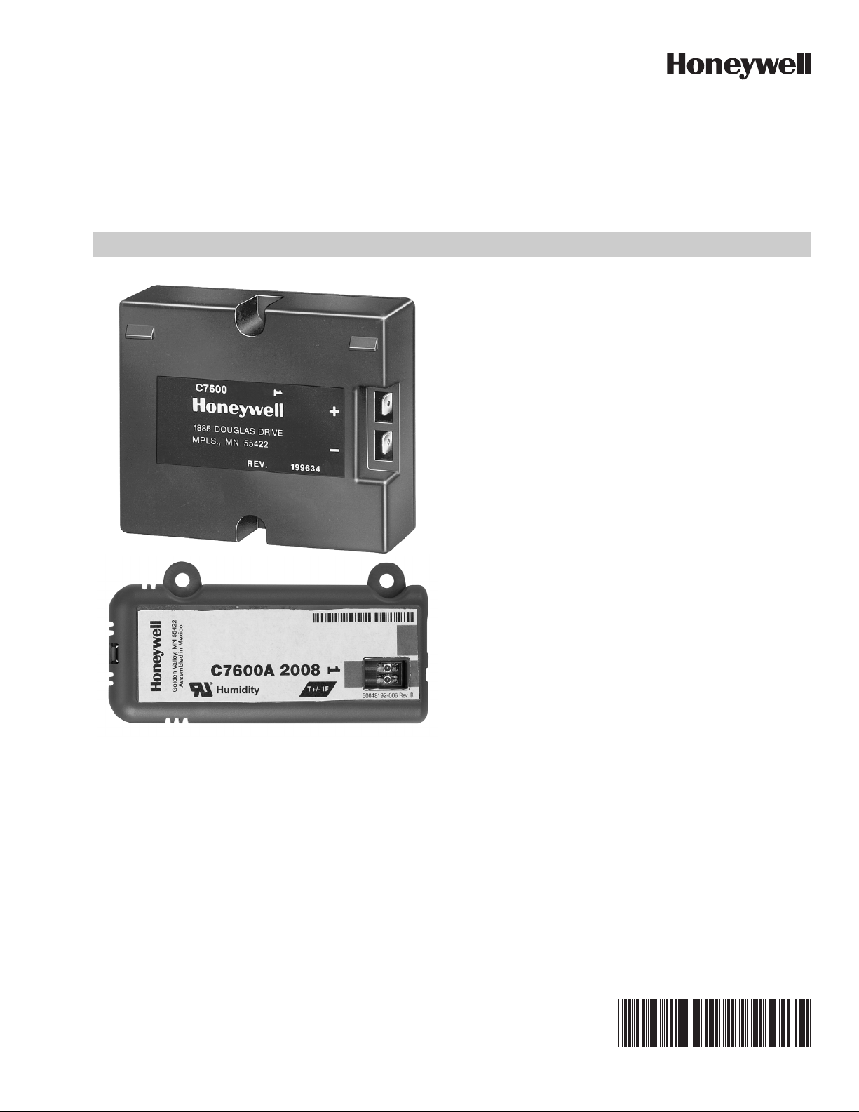
Models: Series 1000 (C7600A100X and C7600C100X) are
in the black case and series 2000 (C7600A200X and
C7600C200X) are in the smaller grey case (see figure on
page 1). Refer to Table 1.
Table 1. C7600A,C Solid State Humidity Sensor Models.
Model Use With
C7600A W7600 or
controller requiring 4-20 mA reverse acting input
C7600C H775 or
controller requiring 4-20 mA direct acting input
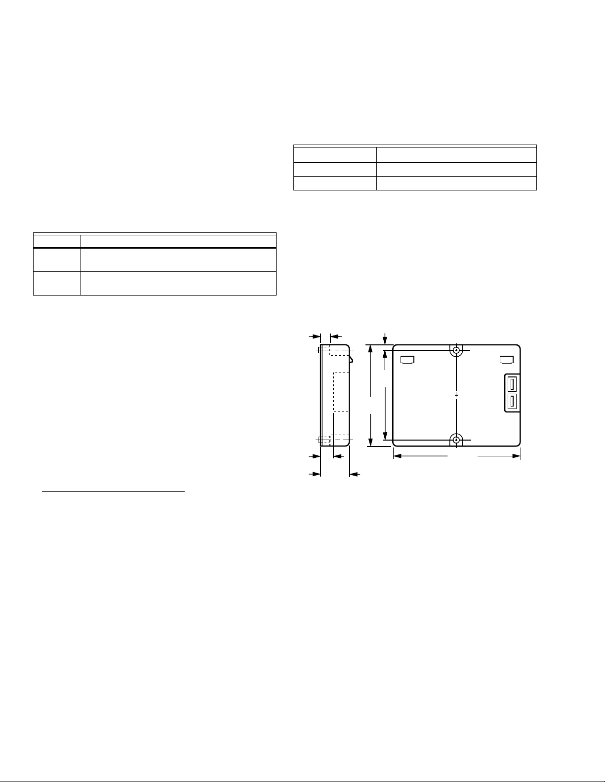
Dimensions: See Fig. 1 and Fig. 2.
Mounting: Duct-mounted indoors, or wall-mounted outdoors
in a location protected from rain, snow, or direct sunlight. A
duct mounting kit
a
is available for the 2000 series sensor
models (C7600A2xxx and C7600C2xxx).
Case: Compact, rugged, lightweight plastic case.
Ambient Temperature Ranges:
Operating: 32°F to 125°F (0°C to 52°C).
Shipping: -40°F to +150°F (-40°C to +66°C).
Table 2. C7600 Output Current vs. Humidity.
Model Relationship
a
C7600A I = -0.16 x RH + 20
C7600C I = +0.16 x RH + 4
a
I = sensor output (in mA); RH = percent relative humidity.
Humidity:
Operating Range: 10 to 90 percent RH, non-condensing.
Time Constants:
Airflow: 500 fpm.
Time: 15 minutes.
Approvals:
Underwriters Laboratories Inc. Flammability Rating:
C7600A: UL94V-0.
C7600C: UL94-5V.
Terminals: Two 1/4 in. (6 mm) quick-connect terminals.
Electrical Ratings:
Input: 12 to 40 Vdc.
Output: 4 to 20 mA signal. The relationship of output current
vs. relative humidity is shown in Table 2 and in Fig. 3 and
Fig. 4 on page 3.
Maximum Power Consumption (at 24V): 0.50 VA.
Electrical Connections: Two 1/4 in. quick-connect terminals.
Fig. 1. C7600A1xxx and C7600C1xxx Humidity Sensor
a
Honeywell part number 50053060-001
dimensions in inches [mm].
ORDERING INFORMATION
When purchasing replacement and modernization products from your TRADELINE® wholesaler or distributor, refer to the
TRADELINE® Catalog or price sheets for complete ordering number.
If you have additional questions, need further information, or would like to comment on our products or services, please write or
phone:
1. Your local Honeywell Automation and Control Products Sales Office (check white pages of your phone directory).
2. Honeywell Customer Care
In Canada—Honeywell Limited/Honeywell Limitée, 35 Dynamic Drive, Toronto, Ontario M1V 4Z9.
International Sales and Service Offices in all principal cities of the world. Manufacturing in Australia, Canada, Finland, France,
Germany, Japan, Mexico, Netherlands, Spain, Taiwan, United Kingdom, U.S.A.
1885 Douglas Drive North
Minneapolis, Minnesota 55422-4386
63-2418—06 2
Page 3
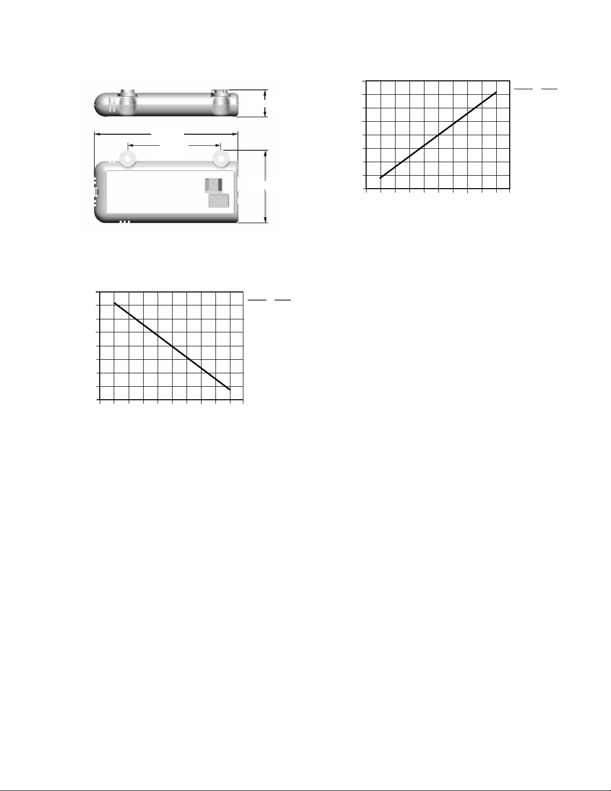
Fig. 2. Approximate dimensions of C7600A2xxx and
M32331
4-1/4 (108)
2-1/64 (55)
51/64 (21)
2-3/4 (70)
HUMIDITY IN % RH
CURRENT IN mA
4
18
8
16
6
14
12
20
10
10
M3130A
18.4
16.8
15.2
13.6
12.0
10.4
8.8
7.2
5.6
10
20
30
40
50
60
70
80
90
20 10090807060504030
RH (%) I (mA)
0
HUMIDITY IN % RH
CURRENT IN mA
4
18
8
16
6
14
12
20
10
10
M3131B
5.6
7.2
8.8
10.4
12.0
13.6
15.2
16.8
18.4
10
20
30
40
50
60
70
80
90
20 10090807060504030
RH (%) I (mA)
0
C7600C2xxx Enthalpy Sensors in inches (mm).
C7600A,C SOLID STATE HUMIDITY SENSORS
Fig. 4. C7600C output current vs. relative humidity.
Fig. 3. C7600A output current vs. relative humidity.
3 63-2418—06
Page 4

C7600A,C SOLID STATE HUMIDITY SENSORS
CAUTION
CAUTION
INSTALLATION
When Installing this Product...
1. Read these instructions carefully. Failure to follow them
could damage the product or cause a hazardous
condition.
2. Check ratings given in instructions and on the product to
ensure the product is suitable for your application.
3. Installer must be a trained, experienced service
technician.
4. After installation is complete, check out product
operation as provided in these instructions.
Electrical Shock or Equipment Damage Hazard.
Can shock individuals or short equipment
circuitry.
Disconnect power supply before installation.
IMPORTANT
All wiring must agree with applicable codes,
ordinances and regulations.
Follow specific instructions furnished by the equipment
manufacturer. If unavailable, follow the procedure below.
Location
The sensor can be mounted in any position where it is exposed
to freely circulating air (with at least 500 fpm airflow) and
proper protection.
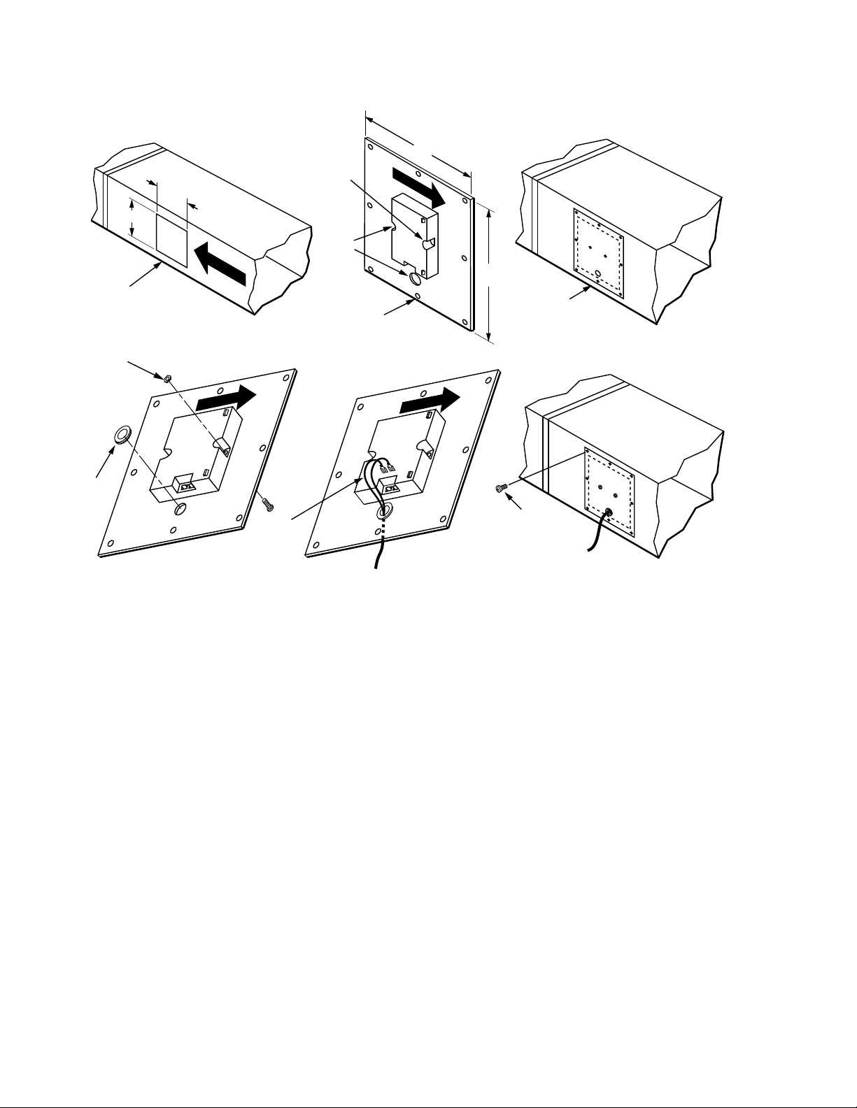
3. Drill two 1/8 in. (3 mm) mounting holes for the sensor
and one 1/2 in. (13 mm) hole for the control wire.
4. Drill eight starting holes in the sheet metal rectangle for
self-tapping sheet metal screws.
5. Center sheet metal rectangle over opening in duct so
there is a 1 in. (25 mm) overlap on all four sides. Then
mark the eight sheet metal screw locations on the duct.
6. Drill eight starting holes in the duct for self-tapping sheet
metal screws.
7. Attach sensor to sheet metal rectangle with 1/8 in.
(3 mm) by 3/4 in. (19 mm) machine screws, washers and
nuts. Attach machine screws from sheet metal outside to
eliminate protrusions and possible sharp edges.
8. Place a rubber grommet in the sheet metal 1/2 in.
(13 mm) hole to protect control wires from abrasions.
9. Put the control wires through the 1/2 in. (13 mm) hole
and wire as shown in the Wiring section.
10. Attach sheet metal rectangle to duct with self-tapping
sheet metal screws. Make sure that airflow over the sensor is as shown in Fig. 7.
Series 2000 mounting instructions
NOTE: The series 2000 sensors can be mounted using the
duct mount sensor kit, Honeywell part number
50053060-001.
The Series 2000 sensors can be mounted directly to the sheet
metal using self tapping sheet metal screws or in the air stream
using the duct mounting kit. Use #6 or #8 screws (screws are
not provided and must be obtained separately).
Mounting Outdoors
IMPORTANT
When selecting the location, make certain the sensor
is not exposed to rain, snow, or direct sunlight.
1. Select a location properly protected.
2. Attach the sensor to the wall with two 1/8 in. (3 mm)
diameter screws.
3. Wire as shown in the Wiring section.
Mounting in Return Air Duct (See Fig. 7)
Use the mounting instructions specific to the sensor model
series, (Series 1000 or series 2000).
Series 1000 mounting instructions
NOTE: Installers need to supply the following: sheet metal
cutter or snips; drill with 1/16 in. (2 mm), 1/8 in.
(3 mm) and 1/2 in. (13 mm) bits; screwdrivers; 1/2 in.
(13 mm) rubber grommet; eight self-tapping sheet
metal screws; and two 1/8 in. (3 mm) by 3/4 in.
(19 mm) machine screws with lock washers and nuts.
1. Cut a 5 in. (127 mm) by 6 in. (152 mm) rectangular hole
in one side of the return air duct.
2. Center the sensor on a 6 in. (152 mm) by 7 in. (178 mm)
piece of sheet metal. Mark locations for mounting screws
and for a hole for the control wire.
Use the dimensions in Fig. 2 on page 3 as a guide. The sensor
must be mounted to allow air flow through the sensor housing
vent slots on the end or side.
The duct mounting kit contains a rod to hold the sensor in the
duct, a flange to secure the sensor rod to the duct wall and to
fill the hole, and a gasket to prevent air from leaking through
the duct wall. The rod has slots for threading the wire to
prevent loose or hanging wire in the duct and can be adjusted
for 6 or 12 inch length. The flange has extended relief for ease
of mounting.
Wiring
Electrical Shock or Equipment Damage Hazard.
Can shock individuals or short equipment
circuitry.
Disconnect power supply before installation.
IMPORTANT
All wiring must agree with applicable codes,
ordinances and regulations.
Follow wiring information furnished by the controller
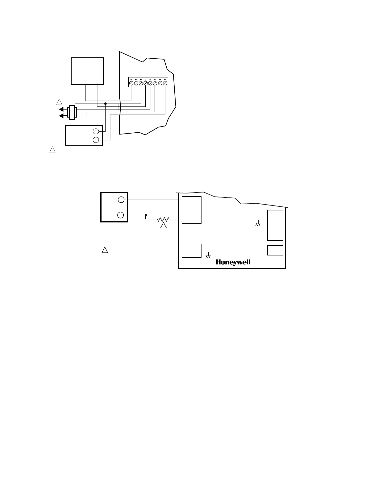
manufacturer or refer to Fig. 5 and 6 for typical wiring hookups.
Note and follow polarity markings.
63-2418—06 4
Page 5
C7600A,C SOLID STATE HUMIDITY SENSORS
M20677
-V+
WHITE
1 2
3 4
5 6
7 8
24 VAC
OUT GND
C7600B
SENSOR
BLACKRED
L1
(HOT)
L2
+
1
_
C7600C
SENSOR
1
POWER SUPPLY. PROVIDE DISCONNECT MEANS AND OVERLOAD
PROTECTION AS REQUIRED.
H775B-E HUMIDITY
CONTROLLER
=20 VDC(+)
=4
=3
=2
=1
=A COM
=V1
=V2
=GND
4=
3=
2=
1=
GND=
V2=
V1=
S7600A
24 VAC
OUT
ANALOG
INPUTS
24 VAC
INPUT
V2=
V1=
24 VAC
OUT
W7600
+
1
M3128A
C7600A
RETURN AIR
HUMIDITY SENSOR
237 OHM, 1 PERCENT, 1/8 WATT
METAL FILM RESISTOR.
1
Fig. 5. Wiring C7600C and C7600B Wall-mounted Sensors
to H775B-E Humidity Controller.
Fig. 6. Wiring C7600A Humidity Sensor to W7600 Control Module.
5 63-2418—06
Page 6
C7600A,C SOLID STATE HUMIDITY SENSORS
M5242B
1
AIR FLOW
5,6
3
4
AIR FLOW
2
6 (152)
5 (127)
6
(152)
7
(178)
10
8
7
9
AIR FLOW
AIR FLOW
Fig. 7. Installing C7600A Solid State Humidity Sensor in return air duct.
63-2418—06 6
Page 7

C7600A,C SOLID STATE HUMIDITY SENSORS
7 63-2418—06
Page 8

C7600A,C SOLID STATE HUMIDITY SENSORS
Automation and Control Solutions
Honeywell International Inc.
1985 Douglas Drive North
Golden Valley, MN 55422
Honeywell Limited-Honeywell Limitée
35 Dynamic Drive
Toronto, Ontario M1V 4Z9
customer.honeywell.com
® U.S. Registered Trademark
© 2010 Honeywell International Inc.
63-2418—06 M.S. Rev. 09-10
Printed in U.S.A.
 Loading...