

Page 1
C7400S Enthalpy Sylk Bus Sensor
M32331
4-1/4 (108)
2-1/64 (55)
51/64 (21)
2-3/4 (70)
INSTALLATION INSTRUCTIONS
Environmental
Operating Temperature range: -40 to 150 °F (-40 to 65 °C)
Storage Temperature range: -40 to 150 °F (-40 to 65 °C)
Shipping Temperature range: -40 to 150 °F (-40 to 65 °C)
Operating Relative Humidity range: 5% to 95% RH non-
condensing
Temperature and Humidity, C7400S:
Temperature sensing range: -40 to 150 °F (-40 to 65 °C)
Humidity sensing range: 0 to 100% RH with 5% accuracy.
PRODUCT DESCRIPTION
The C7400S Sylk Bus sensor is a combination temperature
and humidity sensor, which is intended to be used in
commercial roof top units for sensing air. The sensor is
powered by and communicates on the Sylk Bus. The C7400S
communicates temperature and humidity separately digitally
on the Sylk Bus Communication Protocol.
A separate controller such as the JADE™ Economizer
System (Model W7220) provides power and communications
on the Sylk Bus for the C7400S Sylk Bus sensor.
SPECIFICATIONS
Electrical
Supply Voltage: 7 to 21 Vdc
Power Consumption: 5 mA
Output Rating: 75 ohm load switched at 9600 Baud
Wiring: Sylk Bus: 2-wire (18 to 22 AWG)
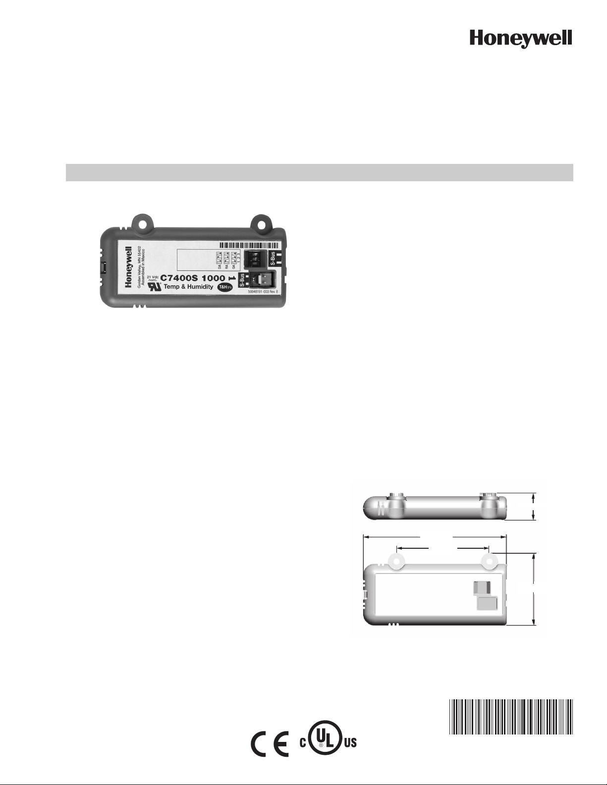
Dimensions (See Fig. 1):
Height: 0.8 inches (20.5 mm)
Width: 2.17 inches (55 mm)
Length: 4.25 inches (108 mm)
Weight: 0.58 lb. (0.265 kg)
Listing Agency Approvals:
EN61000-6-3,EN61000-3-2;EN61000-3-3;EN61000-6-1;
EN60730-1 Annex H.23 (emissions)
Annex H.26 (immunity)
CE Mark FOR EU
Fig. 1. Dimensions in inches and (mm) showing mounting
holes.
62-0332-03
E4436
Page 2
C7400S ENTHALPY SYLK BUS SENSOR
ROD - 1 PIECE
FLANGE - 1 PIECE
GASKET - 1 PIECE
M32281
BEFORE INSTALLATION
Review the “Specifications” on page 1 before installing the
sensor.
When Installing This Product
1. Read these instructions carefully. Failure to follow them
could damage the product or cause a hazardous
condition.
2. Check ratings given in instructions and on the product to
ensure the product is suitable for your application.
3. Installer must be a trained, experienced service
technician.
INSTALLATION AND SETUP
The following installation procedures should be performed in
the order listed:
1. Mounting — see “Mounting” on this page.
2. Wiring — see “Wiring” on page 3.
3. Checkout — see “Checkout” on page 3.
MOUNTING
Once installed, a sensor can be changed to a different
application by simply changing the DIP switch setting.
Sensor Mounting
The sensor can be mounted directly on to the sheet metal of
the unit or can be mounted in the air stream using the duct
mounting kit.
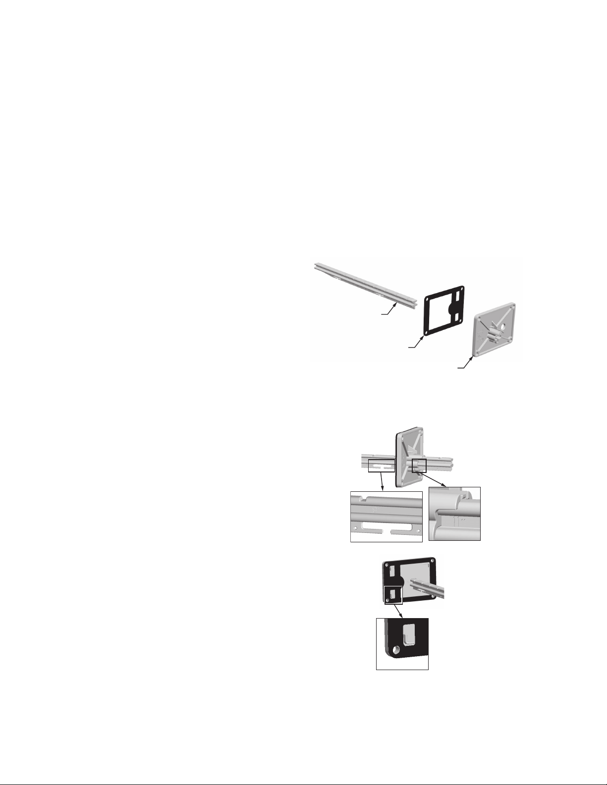
The duct mounting kit contains a rod to hold the sensor in the
duct, a flange to secure the sensor rod to the duct wall and to
fill the hole, and a gasket to prevent air from leaking through
the duct wall. See Fig. 2.
The rod has slots for threading the wire to prevent loose or
hanging wire in the duct and can be adjusted for 6 or 12 inch
length. The flange has extended relief for ease of mounting.
See Fig. 3.
IMPORTANT
Avoid mounting in areas where acid fumes or other
deteriorating vapors can attack the metal parts of the
sensor, or in areas where escaping gas or other
explosive vapors are present.
IMPORTANT
The sensor must be mounted in a position that
allows clearance for wiring, servicing, and removal.
The sensor is mounted directly to the sheet metal using self
tapping sheet metal screws or in the air stream using the duct
mounting kit. Use #6 or #8 screws (screws are not provided
and must be obtained separately). Use the dimensions in
Fig. 1 on page 1 as a guide.
The sensor must be mounted to allow air flow through the
sensor housing vent slots on the end or side.
The Sylk Bus sensor communicates with a controller (such as
the JADE™ Economizer Model W7220) on the two-wire
communication bus and can either be wired using a two pin
header or using a side connector. The unit pack Sylk Bus
sensor includes a two pin Euro connector with the packaging.
The SKU number of the Sylk Bus sensor is C7400S. All OAT
(Outdoor Air Temperature), RAT (Return Air Temperature) and
DAT (Discharge Air Temperature) sensors are the same SKU
number. The sensor is set for the appropriate type of sensing
using the three position DIP switch located on the sensor.
OAT position is OFF, OFF, OFF; RAT is ON, OFF, OFF and
DAT is OFF, ON, OFF. During installation the sensors are set
for the the appropriate usage. See “Sylk Bus Sensor Wiring”
on page 3 for DIP switch details.
Fig. 2. Duct Mounting Kit (Part # 50053060-001).
WIRE HO LDER
EXTENDE D RELI EF
(FOR CORRECT MOUNTING)
LENGTH ADJUSTS
TO 6 OR 12 INCHES
M32282
Fig. 3. Duct Mounting Adjustments.
62-0332—03 2
Page 3

C7400S ENTHALPY SYLK BUS SENSOR
WARNING
CAUTION
DIP
SWITCH
LABEL
M32271
SYLK BUS
TERMINALS
(1 AND 2)
DIP
SWITCHES
(3)
SYLK BUS
2 PIN “EURO”
CONNECTOR
WIRING
All wiring must comply with applicable electrical codes and
ordinances, or as specified on installation wiring diagrams.
Electrical Shock Hazard.
Can cause severe injury, death or property
damage.
Disconnect power supply before beginning wiring, or
making wiring connections, to prevent electrical shock
or equipment damage.
Equipment Damage Hazard.
Electrostatic discharge can short equipment
circuitry.
Ensure that you are properly grounded before
handling the sensor.
Prepare wiring as follows:
1. Strip 1/2 in. (13 mm) insulation from the conductor.
2. Cut a single wire to 3/16 in. (5 mm). Insert the wire in
the required terminal location and tighten the screw.
3. Pull on each wire in all terminals to check for good
mechanical connection.
Table 1. SYLK Bus Sensor Wiring Terminationsa.
Terminal
Type DescriptionNbr Label
1 S-BUS SYLK Bus Sylk Bus Communications
(Sensor Bus)
2 S-BUS SYLK Bus Sylk Bus Communications
(Sensor Bus)
a
Terminals are polarity insensitive.
Table 2. SYLK Bus Sensor DIP Switch Settings.
DIP Switch Positions for Switches 1, 2, & 3
Use
a
DA
b
RA
c
OA
a
DA = Discharge Air
b
RA = Return Air
c
OA = Outside Air
123
OFF ON OFF
ON OFF OFF
OFF OFF OFF
Sylk Bus Sensor Wiring
Use Fig. 4 and Table 1 to locate the wiring terminals for each
Sylk Bus sensor.
Use Fig. 4 and Table 2 to set the DIP switches for the desired
use of the sensor.
Fig. 4. Sylk Bus sensor DIP switches.
CHECKOUT
Refer to the JADE™ Economizer Module (Model W7220)
Installation Instructions (Honeywell form 62-0331).
TROUBLESHOOTING
Refer to the JADE™ Economizer Module (Model W7220)
Installation Instructions (Honeywell form 62-0331).
3 62-0332—03
Page 4

C7400S ENTHALPY SYLK BUS SENSOR
JADE™ is a trademark of Honeywell, Inc.
Automation and Control Solutions
Honeywell International Inc.
1985 Douglas Drive North
Golden Valley, MN 55422
customer.honeywell.com
® U.S. Registered Trademark
© 2011 Honeywell International Inc.
62-0332—03 M.S. Rev. 05-11
Printed in U.S.A.
 Loading...