

Page 1
®
C7232A
C7232B
C7232A,B
Sensor and Controller
CARBON DIOXIDE SENSOR
PRODUCT DATA
FEATURES
• Models available with LCD that provides sensor
readings and status information.
• Non-Dispersion-Infrared (NDIR) technology used to
measure carbon dioxide gas.
• Gold-plated sensor provides long-term calibration
stability.
• Device provides voltage output based on CO
• Models available with SPST relay output.
• Used for CO
• Automatic Background Calibration (ABC) algorithm
based on long-term evaluation reduces required
typical zero-drift check maintenance.
based ventilation control.
2
levels.
2
APPLICATION
The C7232 Sensor and Controller is a stand-alone carbon
dioxide (CO
necessity with HVAC controllers. The C7232 measures the
concentration in the ventilated space or duct. The C7232
CO
2
is used in ventilation and air conditioning systems to control
the amount of fresh outdoor air supplied to maintain
acceptable levels of CO
) sensor for use in determining ventilation
2
in the space.
2
Contents
Application ........................................................................ 1
Features ........................................................................... 1
Specifications ................................................................... 2
Ordering Information ........................................................ 2
Installation ........................................................................ 3
Wiring ............................................................................... 4
Calibration ........................................................................ 6
Checkout .......................................................................... 6
Appendix .......................................................................... 7
® U.S. Registered Trademark
Copyright © 2003 Honeywell International Inc.
All Rights Reserved
63-2571-4
Page 2
C7232A,B SENSOR AND CONTROLLER
5
SPECIFICATIONS
Models: C7232 Sensor and Controller. A stand-alone carbon
dioxide (CO
(one analog and one spst relay).
) sensor with two jumper-adjustable outputs
2
C7232A: Wall mount model.
C7232B: Duct mount model.
NOTE: Models are available with or without a 4-digit LCD
that indicates the current CO
concentration.
2
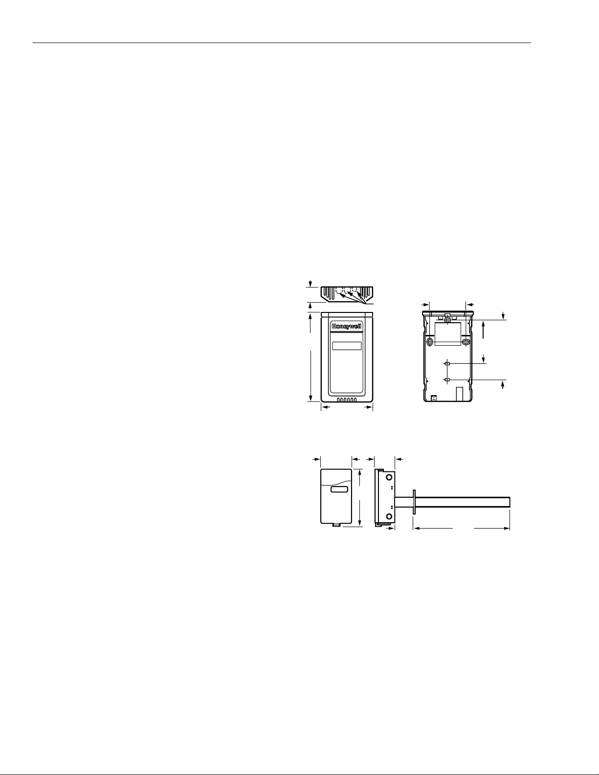
Dimensions:
C7232A: See Fig. 1.
C7232B: See Fig. 2.
Sensor Performance Ratings:
Response Time: 2 min.
Carbon Dioxide Sensor:
Operation: Non-dispersive infrared (NDIR).
Sampling: Diffusion.
Range: 0 to 2000 ppm ±5% and ±50 ppm.
Annual Drift: 20 ppm (nominal).
Electrical Ratings:
Power Supply: 24 Vac ±20%, 50/60 Hz (Class 2).
Maximum Power Consumption: 3W.
Peak Current (at 20 ms): 600 mA.
Relay:
Configuration: Shipped N.O. (reconfigure with software.)
Contact Rating: 1A at 50 Vac/24 Vdc.
Minimum Permissible Load: 1 mA at 5 Vdc.
Linear Analog Output:
Voltage: 0/2-10 Vdc (resistive load greater than
5000 ohms).
Current: 0/4-20 mA (resistive load less than 500 ohms).
Connections:
Wiring:
C7232A: 20-gauge cable with six 8 in. leadwires.
C7232B: 20-gauge cable with six 6 in. leadwires.
Mounting:
C7232A: Vertical surface with standard single-gang junction
box.
C7232B: Sheet metal duct with a sampling tube.
Automatic Background Calibration (ABC) default: On.
Approvals:
Underwriters Laboratories Inc. Component Recognition:
UL94-5V, File No. E191465.
CE.
C7232A: NEMA1.
C7232B: NEMA3.
1
(25)
-1/16
(128)
3-5/32 (80)
KNOCKOUTS
FOR
EUROPEAN
APPLICATIONS
2-3/8 (60)
STANDARD
2-3/8
(60)
UTILITY
CONDUIT
BOX
(2X4)
MOUNTING
HOLES
M17540
Outputs (Jumper Adjustable, see Table 2):
Fig. 1. C7232A dimensions in in. (mm).
Analog: 0-10 Vdc (Default: 2-10 Vdc, 500 to 1500 ppm).
Relay: Normally Open Spst (Default: Close at 800 ppm).
3-5/16 (84)
Ambient Ratings:
1-13/16
(46)
Temperature:
Operating: +32°F to +122°F (0°C to +50°C).
Storage: -4°F to +158°F (-20°C to +70°C).
5-5/8
(142)
Relative Humidity (non-condensing): 0 to 95 percent.
CO
Pressure Dependence: 1.4% change in reading per
2
1 kPa deviation from 100 kPa.
M17592
1-5/8
(41)
8 (203)
Fig. 2. C7232B dimensions in in. (mm).
ORDERING INFORMATION
When purchasing replacement and modernization products from your TRADELINE® wholesaler or distributor, refer to the
TRADELINE® Catalog or price sheets for complete ordering number.
If you have additional questions, need further information, or would like to comment on our products or services, please write or
phone:
1. Your local Honeywell Automation and Control Products Sales Office (check white pages of your phone directory).
2. Honeywell Customer Care
1885 Douglas Drive North
Minneapolis, Minnesota 55422-4386
In Canada—Honeywell Limited/Honeywell Limitée, 35 Dynamic Drive, Scarborough, Ontario M1V 4Z9.
International Sales and Service Offices in all principal cities of the world. Manufacturing in Australia, Canada, Finland, France,
Germany, Japan, Mexico, Netherlands, Spain, Taiwan, United Kingdom, U.S.A.
63-2571—4 2
Page 3
INSTALLATION
B
S
S
L
C7232A,B SENSOR AND CONTROLLER
When Installing this Product...
1. Read these instructions carefully. Failure to follow them
could damage the product or cause a hazardous
condition.
2. Check the ratings given in the instructions and on the
product to make sure the product is suitable for your
application.
3. Installer must be a trained, experienced service
technician.
4. After installation is complete, check out product
operation as provided in these instructions.
IMPORTANT
All wiring must agree with applicable codes,
ordinances and regulations.
CAUTION
Health Hazard.
Improper use can create dangerous situations.
Use in application for sensing carbon dioxide only.
For life-safety applications, this device can function
only as a secondary or lesser device.
CAUTION
Electrical Shock or Equipment Damage Hazard.
Can shock individuals or short equipment
circuitry.
Disconnect power supply before installation.
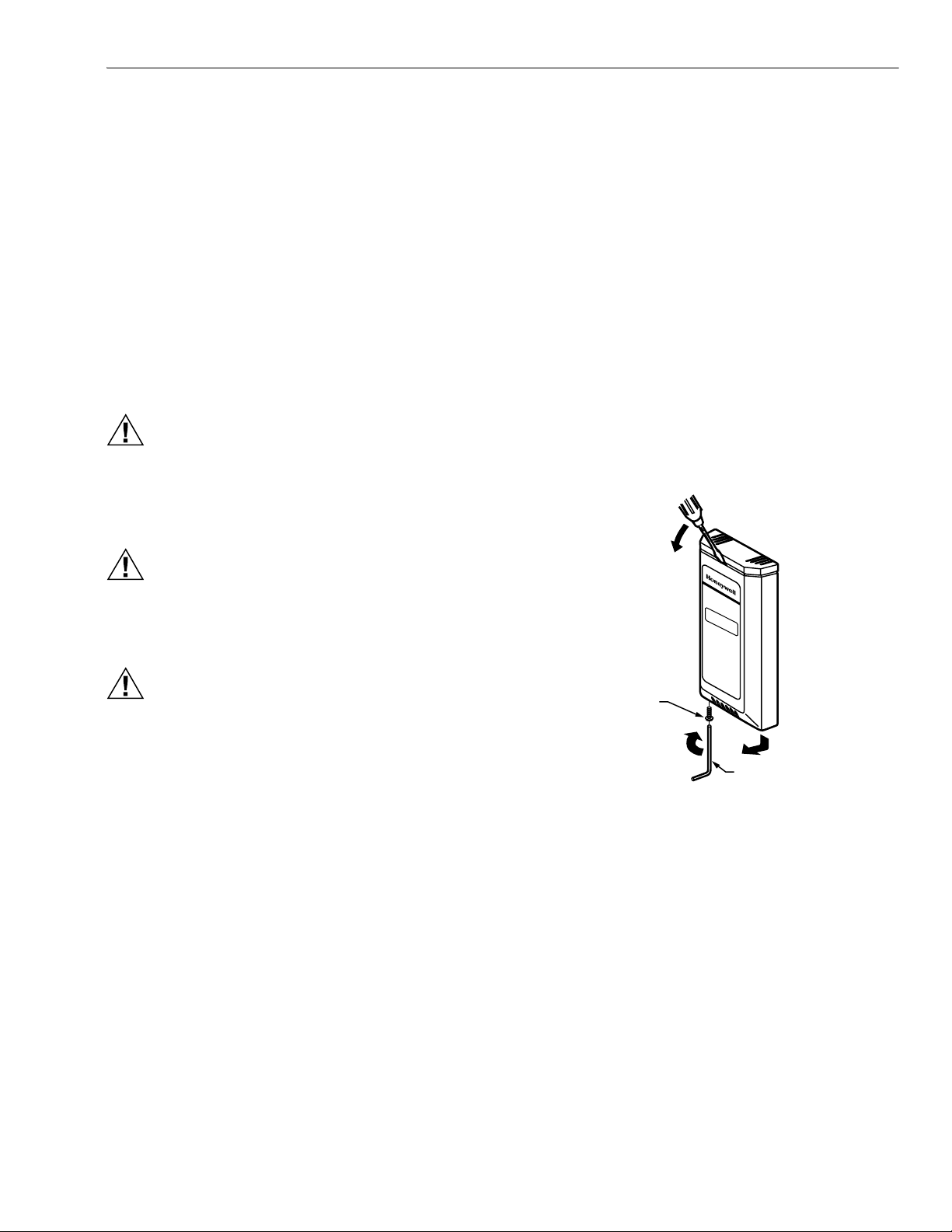
C7232A Cover Removal/Replacement
C7232A Cover Removal (see Fig. 3)
1. Remove button head socket cap screw and set it aside.
2. Insert the head of a small screwdriver into the slot at the
center and near the top of the cover.
3. Gently pull the handle down toward the bottom of the
device until a small gap between the subbase and the
cover appears.
4. Remove the screwdriver and pull the cover straight
down until it meets a stop.
5. Pull the cover straight off the subbase.
C7232A Cover Replacement
1. Feed the wires through the opening in the subbase.
2. Place the cover, with a small gap at the top, flat on top
of the subbase.
3. When the cover rests flat on the subbase, slide it
straight up until it latches in place.
B
UTTON HEAD
CAUTION
Equipment Damage Hazard.
Electrostatic discharge can short equipment
circuitry.
Ensure that you are properly grounded before
handling the unit.
OCKET CAP
CREW
A
M17541
Fig. 3. C7232A cover removal.
C
ALLEN TOO
3 63-2571—4
Page 4

C7232A,B SENSOR AND CONTROLLER
2
B
S
S
1
Location and Mounting
C7232 Sensors mount directly on the wall, sheet metal duct,
or a panel. When planning the installation, allow enough
clearance for maintenance and service. Mount the sensor in a
well-ventilated area.
FLOW
NOTES: Do not install the sensor where it can be affected by:
— drafts or dead spots behind doors and in corners.
— air from ducts.
Wall Mounting
The C7232 Wall Mount models can be mounted using two or
four screws:
1. Remove C7232 cover.
2. Mount the subbase to the wall using washers and two or
four screws (not supplied) appropriate for the wall
material.
NOTE: When mounting on a junction box, see Fig. 4.
3. Replace the cover.
Duct Mounting (see Fig. 5)
1. Place gasket on aspiration tube.
IMPORTANT
Ensure largest tab at tube control end is at the top.
2. Insert tube into duct; attach using screws and washers.
IMPORTANT
Leakage into the duct or the C7232 box cover from
the room will skew the sensor readings. Ensure the
box cover and duct seal completely.
3. Place o-ring on tube end; mount the control to the tube.
M1759
Fig. 5. Duct mounting (C7232B).
WIRING
The factory ships the device with the output default settings
shown in Tables 2 and 3. Set the jumpers and wire the device
(see Table 1 and Fig. 6).
CAUTION
Electrical Shock or Equipment Damage Hazard.
Can shock individuals or short equipment
circuitry.
Disconnect power supply before installation.
STANDARD UTILITY CONDUIT BOX
NO. 6 SCREW
FRONT
COVER
UTTON HEAD
OCKET CAP
CREW
NO. 6 SCREW
Fig. 4. Junction box mounting (C7232A).
SUBBASE
M1754
CAUTION
Equipment Damage Hazard.
Electrostatic Discharge Can Short Equipment
Circuitry.
Ensure that you are properly grounded before
handling the unit.
IMPORTANT
1. All low voltage connections to this device must be
24 Vac Class 2.
2. All wiring must comply with applicable local codes,
ordinances and regulations.
Table 1. C7232 Wiring Connections (see Fig. 6).
Wire Color Designation Function
Red G+ 24 Vac Hot
Black G0 24 Vac Common
Yellow OUT1 Analog Output Signal
Brown M Analog Output Common
Orange NO Relay Output Normally Open
Green COM Relay Output Common
63-2571—4 4
Page 5

C7232
ANALOG
24V
OUT
+
–
RED
BLACK
YELLOW
BROWN
ORANGE
GREEN
L1
(HOT)
L2
1
1 POWER SUPPLY. PROVIDE
DISCONNECT MEANS AND
OVERLOAD PROTECTION
AS REQUIRED.
M17543
Fig. 6. Wiring the C7232.
Input Signal
The C7232 Sensors have an adjustable range. These ranges
are determined by the SW1 and SW2 jumper settings (see
Table 2).
Table 2. CO
SW1 SW2 AN (ppm) Relay
Range Jumper Settings
2
a
(ppm)
On On 0 to 1000 1000
On Off 0 to 2000 1200
Off
b
On
b
500 to 1500 800
Off Off 500 to 2000 1200
a
When the level reaches this value, the contacts close; when
the level drops 100 ppm below this value, the contacts open.
b
Setting when shipped from the factory.
Output Signal
The output signal can be adjusted for 0/2-10Vdc or 0/4-20mA
(see Table 3).
C7232A,B SENSOR AND CONTROLLER
Table 3. Output Signal Jumper Settings
OUT
AN
0-100% 20-100%
Voltage 0-10Vdc 2-10Vdc
Current 0-20 mA 4-20 mA
NOTES:
— On duct models, remove the screw holding the
board in place to view jumper settings on reverse.
(See Fig. 7.)
— The CO
are independent of each other. 0-100% and
settings and the output signal settings
2
20-100% are simply markings for the OUT jumper
settings on the sensor (to differentiate between
the two voltage and the two current ranges) and
do not refer to or alter the ppm range chosen.
SW2SW1 OUT
ON
OFF
ON
OFF
AN
20 – 100%
0 – 100%
Current
Voltage
Fig. 7. C7232 default jumper settings.
M19424
Example
For a CO2 setting of 0-2000 ppm and a voltage output of 0-10 Vdc, the output would be as shown in Table 4 (arbitrary points
along the analog curve).
Table 4. 0-10 Vdc Output Example.
CO2 Level (ppm)
Voltage Output (Vdc)012345678910
For a CO
along the analog curve).
setting of 0-2000 ppm and a voltage output of 2-10 Vdc, the output would be as shown in Table 5 (arbitrary points
2
CO
Level (ppm)
2
Voltage Output (Vdc) 2 3 4 5 6 7 8 9 10
0 200 400 600 800 1000 1200 1400 1600 1800 2000
Table 5. 2-10 Vdc Output Example.
0 250 500 750 1000 1250 1500 1750 2000
5 63-2571—4
Page 6

C7232A,B SENSOR AND CONTROLLER
CALIBRATION
Typically, calibration is unnecessary. No calibration kits are
available. However, if CO
chamber using a general gas purge device, the sensor can be
rezeroed:
IMPORTANT
Any CO
zero level resulting in incorrect CO
1. Once the sensor stabilizes, use a screwdriver to
connect the two MENU soldering pads.
2. The display should indicate CAL.
3. Execute the zero calibration by connecting the two
ENTER soldering pads.
4. The display should return to providing the measured
CO
2
present during calibration skews the sensor
2
level.
gas can be purged from the sensor
2
level reports.
2
CHECKOUT
Perform a quick test of the unit with the unit powered:
1. Stand close to the unit and breathe air into the sensor.
2. Check the CO
ensure a strong rise.
3. When connected to a damper in a ventilation system,
the controller typically signals an increase in air flow.
level registered by the controller to
2
63-2571—4 6
Page 7

APPENDIX
4
IMPORTANT
This page is only for models with date code prior to 0309.
Pre 0309 Date Code Jumper Settings
C7232A,B SENSOR AND CONTROLLER
Input Signal
The C7232 Sensors have an adjustable range. These ranges
are determined by the SW2 and OUT1 jumper settings (see
Table 6).
NOTE: When choosing analog output, be sure to set the
SW1 jumper to the On position.
Table 6. CO
Range Jumper Settings for models
2
with date code prior to 0309.
Jumper SW1 Jumper SW2
Jumper Setting
b
OUT1
AN1 X
AN2
Relay Switching
b
a
a
On
X
Off On
c
—
c
—
X
X
a
Setting when shipped from the factory.
b
OUT1 jumper setting does not affect the Relay Switching.
c
The analog output will not work properly when SW1 is Off.
d
When the level reaches this value, the contacts close; when the
level drops 100 ppm below this value, the contacts open.
a
Off
0 to 1000 0 to 2000
500 to 1500 500 to 2000
800
1000
d
d
1200
d
Output Signal
The output signal can be adjusted for 0/2-10Vdc or 0/4-20mA
(see Table 7).
Table 7. Output Signal Jumper Settings for models
with date code prior to 0309.
AN1 and AN2 (set
both the same)
0-100% 20-100%
OUT
Voltage 0-10Vdc 2-10Vdc
Current 0-20 mA 4-20 mA
NOTES:
— On duct models with date code prior to 0309, remove
the screw holding the board in place to view jumper
settings on reverse. (See Fig. 8.)
—The CO
independent of each other. 0-100% and 20-100% are
simply markings for the OUT jumper settings on the
sensor (to differentiate between the two voltage and the
two current ranges) and do not refer to or alter the ppm
range chosen.
SW2SW1 OUT
ON
OFF
settings and the output signal settings are
2
OFF
ON
0 – 100%
AN2 AN1
20 – 100%
Current
Voltage
Current
Voltage
OUT1
Select
AN1
AN2
M2049
Fig. 8. C7232 default jumper settings for models
with date code prior to 0309.
7 63-2571—4
Page 8

Automation and Control Solutions Honeywell International Honeywell Europe S.A. Honeywell Latin American
Honeywell International Inc. Honeywell Limited-Honeywell Limitée Control Products 3 Avenue du Bourget
1985 Douglas Drive North 35 Dynamic Drive Honeywell Building 1140 Brussels 480 Sawgrass Corporate Parkway
Golden Valley, MN 55422 Scarborough, Ontario 17 Changi Business Park Central 1 Belgium Suite 200
M1V 4Z9 Singapore 486073 Sunrise FL 33325
Region
63-2571—4 B.B. Rev. 3-03 www.honeywell.com
Printed in U.S.A. on recycled
paper containing at least 10%
post-consumer paper fibers.
 Loading...