

Page 1
PRODUCT HANDBOOK
C7195A
WATER FLOW SENSOR
EN2R-- 9029 0101R2--NE
APPLICATION
The sensor is primarily designed to measure the Domestic
Hot Water (DHW) flow rate in domestic appliances as follows:
Combi boiler
Instanteneous Water Heater (IHW)
Other systems such as applications where the
instanteneous DHW is produced from district heat
input.
Contents
General Page
Description 2........................................
Typical applications 3................................
Technical
Specifications 4.....................................
Electrical specifications 5.............................
Performance 6......................................
General considerations 7.............................
Dimensional drawing 8...............................
Various
Standards and approvals 9............................
Ordering information 10..............................
Associated products 11...............................
Subject to change without notice. Printed in the Netherlands.
Page 2
EN2R-- 9029 0101R2--NE
2
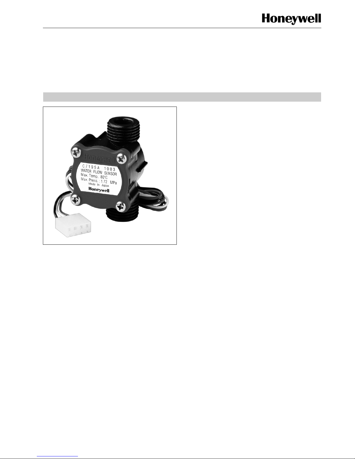
DESCRIPTION
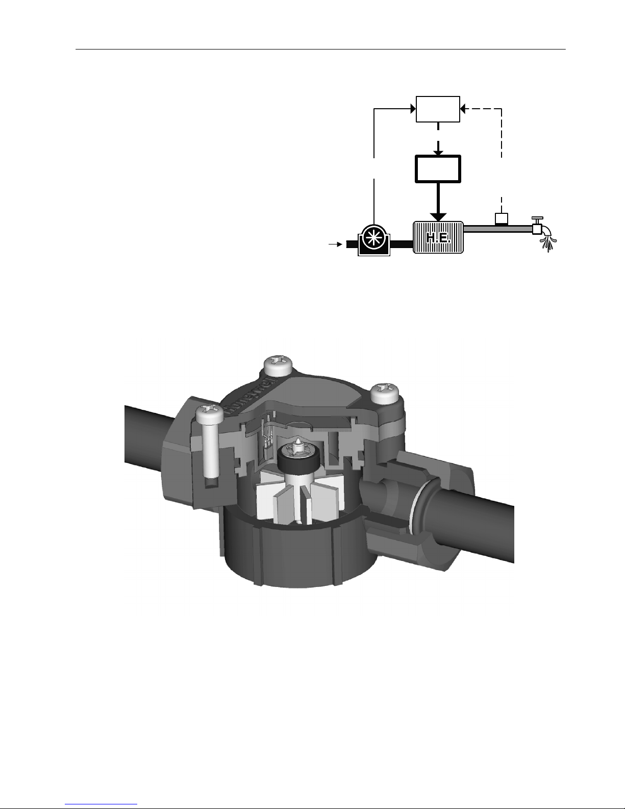
The C7195A is a mechanical water flow sensor (fig. 2.).
A turbine rotates with water flow. The turbine supports a
magnet which rotates in front of a Hall effect sensor.
This Hall effect sensor picks up the field of the magnet giving
a pulsed output.The output is directly proportional to the water
flow through the sensor.
This frequency output is easily processed by an electronic
controller which can then modulate the burner load (for
feed--forward loop) or simply open heat demand when the
flow reaches its defined minimum rate (electronic flow switch).
The sensor body is constructed from pressure and
temperature resistant plastic, with easy connections to
traditional pipes used in domestic appliances.
Feed forward control loop concept
See fig. 1.
Electronic
Controller
Flow rate input
for modulation
Cold water
Modulating control
Heat
supply
Temperature feed back
Option: Compensation
of tolerances and
hysteresis
_C
T7335
C7195A
Domestic
hot water
Fig. 1. Feed forward control loop concept
Fig. 2. Open view C7195
Page 3
EN2R-- 9029 0101R2--NE
3
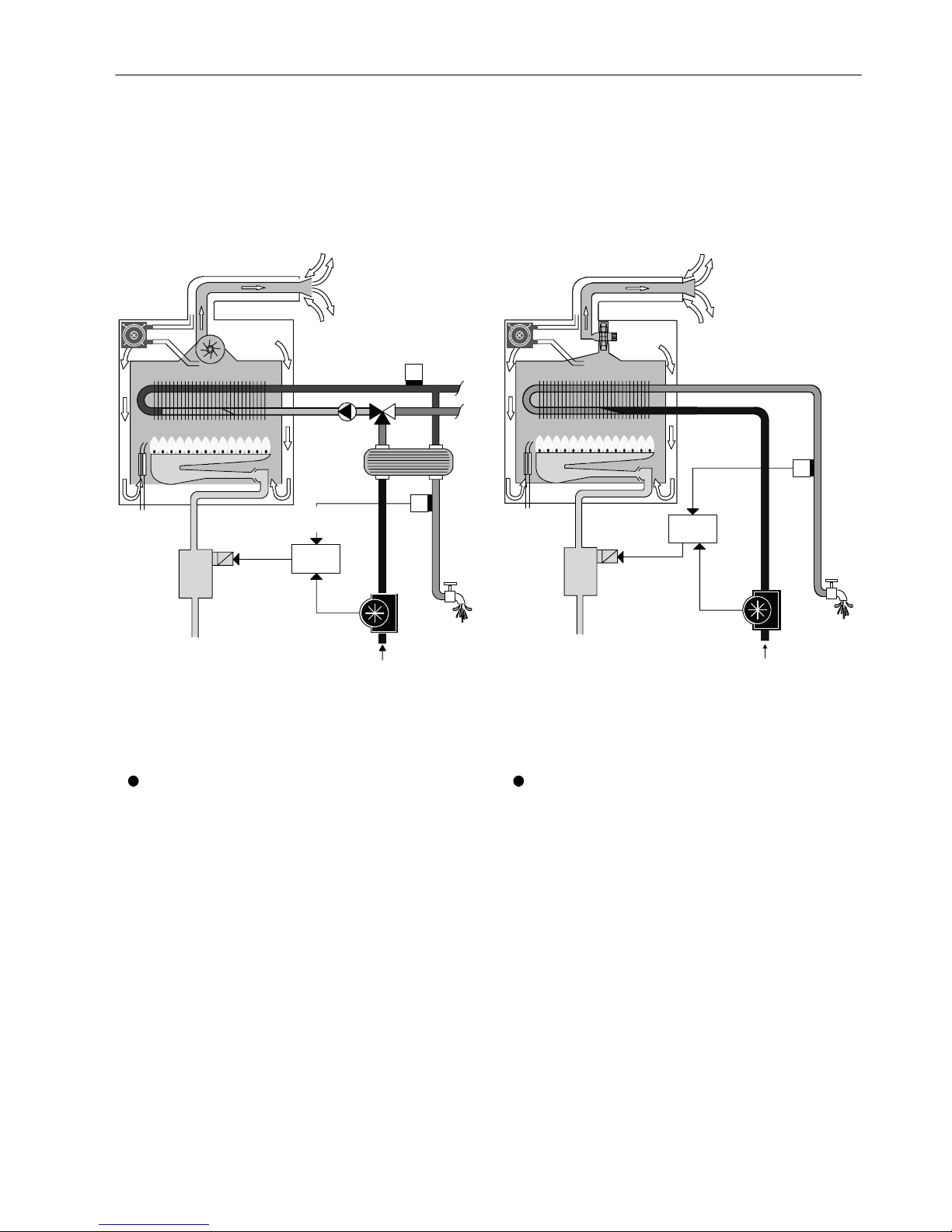
TYPICAL APPLICATIONS
The C7195A sensor is designed to measure the Domestic Hot
Water (DHW) flow rate in appliances as follows:
Combi boiler (instanteneous or with small buffer)
Instanteneous Water Heater (IWH), gas or electric
powered.
Other systems where DHW is produced instantaneously
Modulation input
and/or electronic
flow switch
Modulating
control
Electronic
controller
Cold water
Temperature
feed back
Domestic hot
water
_C
_C
Fig. 3. Instanteneous combi boiler with feed forward or
feed back control loop
Temperature
feed back
Modulating
control
Modulation input
and/or electronic
flow switch
Electronic
controller
Cold water
Domestic
hot water
_C
Fig. 4. Instanteneous water heater with feed forward or
feed back control loop
For the above mentioned appliances, the sensor can be used in two specific ways:
1
Feed forward control loop
This is an advanced electronic control concept which
improves the DHW temperature control thanks to fast
reaction to flow rate changes. Indeed, before the
temperature sensor sees a change in hot side, the
electronic board can react promptly following the flow
measurement. A temperature sensor can be used
anyway as an option to compensate the tolerances and
hysteresis of the complete system.
2
Feedback control loop
This is the traditional electronic control, reacting to the
DHW temperature sensor output. A flow detector is
needed to detect when the DHW is tapped.
The C7195 water flow sensor can be used as an
electronic flow switch with the following advantages
over ON/OFF switches:
Flexibility:
Electronically (auto)adjustable ON--point, for
instance depending on DHW temperature setting
point (to avoid ON/OFF recycling)
Safety:
Can not be blocked in ON position (the turbine can
only turn with flow).
Page 4
EN2R-- 9029 0101R2--NE
4
SPECIFICATIONS
Model
C7195A water flow sensor
Ambient temperature
--20 ... + 85 _C
Dimensions
See fig. 11.
Fluid
Water for sanitary use
Permissible fluid temperatur
0 ... 80 _C
Minimum operating flow rate
1.5 liter/minute or lower
Maximum operating flow rate
30 liter/minute
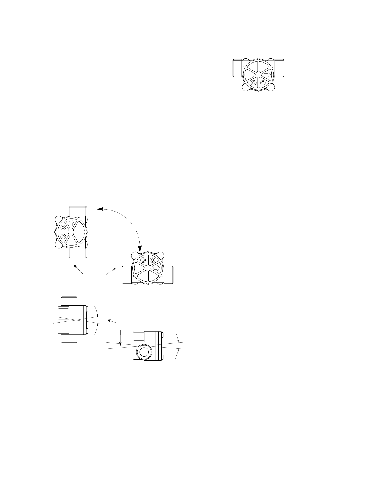
Mounting position
The shaft of the rotor shall be horizontal ¦ 5_. See fig. 5.
Provided the shaft of the rotor is horizontal, most
positions are acceptable, but the position as indicated in
fig. 6. is not recommended because water will remain in
the sensor when the installation is drained (frost risk).
All positions
Shaft axis
Shaft axis
5_
5_
5_
5_
Fig. 5. Mounting positions
Fig. 6. Not recommended mounting position
Measuring range
2.1 ... 30 liter/min
Nominal output frequency
f = Q x 7.0 (Q = flow rate in l/min; f = pulse signal in Hz) with
> 60 mm straight pipe on both sides.
Accuracy
¦ 10% of measurement over the measuring range.
Withstand pressure
When a water pressure of 17.5 bar is applied, no external
leakage shall be measured and no body damage shall occur.
Water connections
PF
1
/2” minimum 8 mm (4.4 threads)
Recommended tightening torque of inlet/outlet connections
2.5 ... 3.5 Nm
Pressure drop
0.15 bar or less at 10 l/min flow rate.
(Outlet pressure is at atmospheric pressure)
Endurance
Indicated value will shift < 5% under following conditions:
10000 hr at 10 l/min and 20 _C
7000 hr at 4 l/min and 45 _C
or
100,000 cycles ON/OFF at 10 l/min and 45 _C
Page 5

EN2R-- 9029 0101R2--NE
5
ELECTRICAL SPECIFICATIONS
Nominal voltage (Vcc): 12 V (absolute maximum: 18 V)
Current (I
sink
): 10 mA (absolute maximum: 15 mA)
Output saturation voltage (V
sat
):< 0.4 V
with output “ON” and at I
sink
=10mA
Supply current (I
cc
): 8 mA with output “OFF”
Electrical connection
C7195A 1003: see fig 7.
C7195A 1011: see fig 7.
C7195A 1029: see fig 8.
C7195A 1037: see fig 9.
Lead wire length
C7195A 1003: 500 mm
C7195A 1011: 1000 mm with 550 mm insulation tube
C7195A 1029: 160 mm
C7195A 1037: 250 mm
Electrical code
Red: V
cc
White: V
out
Black: ground
Duty cycle of electrical output signal
30 ... 70%
Housing: 5239-- 042
Terminal: 5167T
4--V
cc
:red
3--V
out
:white
2 -- Blank
1 -- Ground: black
AWG24 UL1430
Fig. 7. Electrical connection C7195A 1003/1011
Housing: JST EPL--03V
Terminal: JST SLF--01Y--Pt.3E
1 -- Ground: black
2--V
out
:white
3--V
cc
:red
AWG24 UL1430
Fig. 8. Electrical connection C7195A 1029
A
WG24 UL1430
Lumberg serie 3150 03K07 S01
Red
Black
White
Fig. 9. Electrical connection C7195A 1037
10 kτ
+
V
cc
+V
out
Gnd
5 ... 12
V
V
cc
< 0.4 V
Hall IC
Fig. 10. Suggested interface schematic
Page 6

EN2R-- 9029 0101R2--NE
6
PERFORMANCE
Design life
10,000 hour continious operation at 10 l/minute at 20 _C
7,000 hour continious operation at 10 l/minute at 45 _C
or:
100,000 cycles operation (ON = 5 s/OFF = 5 s) at 10 l/minute
at 45 _C.
After life test accuracy must be within ±5% of measured
value at first stage.
Page 7

EN2R-- 9029 0101R2--NE
7
GENERAL CONSIDERATIONS
When magnetic materials like iron or materials which
generates magnetism are close to the flow sensor, operation
characteristics may change.
In order to avoid the invasion of small particles like sand, iron
and rust into the water flow sensor, it is advisable to install a
mesh filter.
The waterflow to the inlet of the flow sensor should be
undisturbed to meet the accuracy specifications.
If a device causes significant flow disturbance at the inlet of
the device, contact your Honeywell representative.
Page 8

EN2R-- 9029 0101R2--NE
8
DIMENSIONAL DRAWING
Made in Japan
7.5
11
8
9635
MODEL C7195A 1003
Max.Pr ess.:1 .72 MPa
Max.Temp: 80 _C
>PPS<
40
30
30.5
30.5
11
11
PF1/2“
PF1/2“
15
2.5
12.5
11
7.5
7.5
61
WATER FLOW SENSOR
* Cable connection A 1029
*
Fig. 11. Dimensional drawing C7195
Page 9

EN2R-- 9029 0101R2--NE
9
STANDARDS AND APPROVALS
Approvals
The C7195 water flow sensor has been appproved according
the United Kingdom Byelaws and Regulations
Certificate N0. 9711081, and can therefore be used in potable
water applications.
Other countries in general accept this certification.
For more details please c ontact Standards and Appprovals
department, Honeywell Combustion Control Center NL05.
Page 10

EN2R-- 9029 0101R2--NE
10
ORDERING INFORMATION
C
Water flow sensor
719
A 9999
Specification number
Ordering Specification number
5
Mechanical type (turbine)
Fig. 12. Model number chart C7195A water flow sensor
Page 11

EN2R-- 9029 0101R2--NE
11
ASSOCIATED PRODUCTS
Electronic controller
W4115C series for IWH application
W4115B series for Combi boiler application
W7073C series for Combi boiler application
Temperature senso rs
T7335 series(NTC thermistor probes), many options
available.
Home and Building Control
Combustion Controls Center Europe
Honeywell BV
Phileas Foggstraat 7
7821 AJ Emmen
The Netherlands
Tel: +31 (--)591 695911
Fax: +31 (--)591 695200
http://europe.hbc.honeywell.com
 Loading...