

Honeywell C7110C1001, C7110D1009 DATASHEET
HONEYWELL EXCEL 5000 OPEN SYSTEM
FEATURES
• Mountable on 2.36 in. (60 mm) wall outlet box or
• With setpoint adjustment dial (Celsius relative or
C7110C1001/D1009
WALL MODULES
SPECIFICATION DATA
directly on a wall.
Celsius absolute scale) (C7110D1009, only).
GENERAL
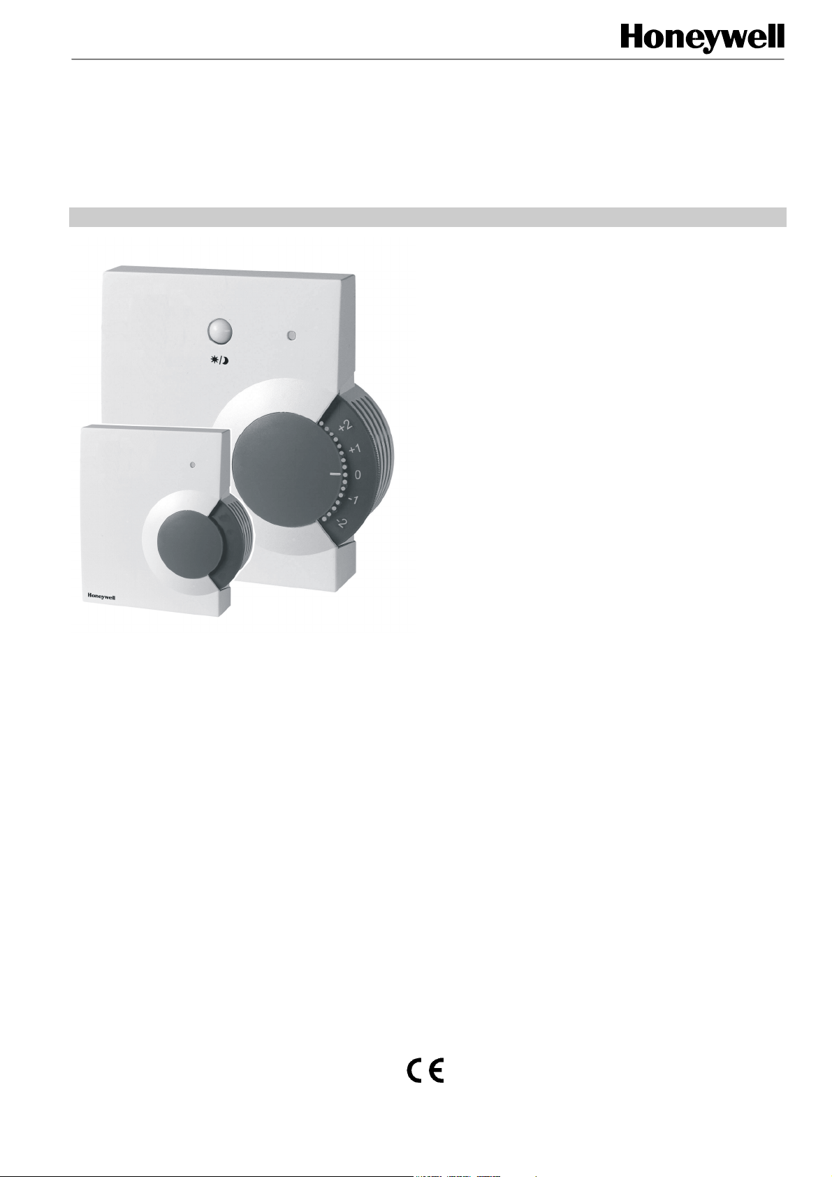
The C7110C1001 and C7110D1009 are wall modules
which can be directly wired to Honeywell Excel 600, 500,
100, 50, and 20 Controllers.
Please refer to the technical specifications of the individual
controllers in order to determine their suitability for use in
conjunction with a given wall module application.
• With CO
level (C7110C1001) or occupancy (C7110D1009).
• With space temperature sensor (C7110D1009, only).
• With occupancy bypass button (C7110D1009, only).
• Locking cover on all models.
• Operating range 43 to 104°F (6 to 40°C).
• CE approved.
• IP 30 housing.
• Compact.
• Configurable using Honeywell's free UIP software
module (see section "Specifications" on page 4).
• Self-calibrating.
• CO
binary output.
• Life-span: min. 13 years.
sensor and LED indicating either CO2
2
output (pin 2) configurable as an analog or
2
DESCRIPTION
The C7110C1001 is equipped with a CO2 sensor. The
C7110D1009 is equipped with both a CO
space temperature sensor.
The C7110D1009 also features a setpoint adjustment dial.
By default, the “Celsius Relative” type (-5 to +5) is
mounted, but can be easily replaced with the “Celsius
Absolute” type (12 to 30°C).
The C7110C1001 features a CO
The C7110D1009 features an occupancy bypass button
and an occupancy LED.
level LED.
2
sensor and a
2
® U.S. Registered Trademark
Copyright © 2009 Honeywell Inc. • All Rights Reserved EN0B-0457GE51 R0309
C7110C,D WALL MODULES
F
t
r
resis
t
o
hms
SPECIFICATIONS
Table 1. C71100C1001 and C71100D1009 Wall Module models
model no.
C7110C1001 --
C7110D1009
NOTE: For wall module settings and wiring diagrams, refer
to the C7110C,D Installation Instructions (product
literature no.: EN1B-0257GE51). Some features may
not be available with all controllers (see Table 1).
Construction:
Two-piece construction, a cover and an internally wired subbase. Field wiring 16 to 22 AWG (1.5 to 0.34 mm
to a terminal block on the PCB.
Temperature Sensor Operating Range:
43…104°F (6…40°C).
space temp.
sensor
3 3
Temperature Sensor Accuracy
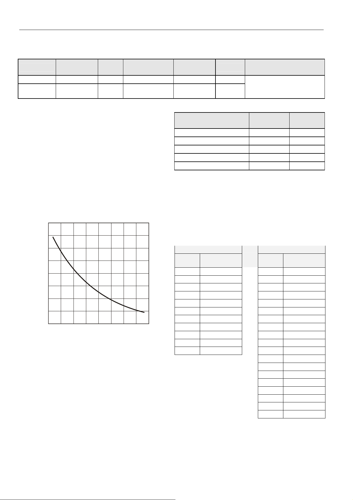
20 kΩ Sensor:
The C7110D1009 is equipped with a 20 kΩ NTC temperature
sensor following a specific temperature-resistance curve (see
Fig. 1).
80 K
70 K
)
60 K
50 K
ance (
40 K
30 K
ical
20 K
elec
10 K
30
40 50 60 70 80 90 100 110
0 10 20 30 40
temperature (degrees)
Fig. 1. Temperature vs. resistance for 20 kΩ sensor
Honeywell controllers used with these Wall Modules employ
an algorithm that provides readings close to the actual
temperature. Table 2 summarizes the sensor accuracy for
normal operating temperatures.
CO2
sensor
3
setpoint
adjustment dial
-- -- CO2 level
12 to 30°C (abs.)
± 5 K (rel.)
2
) connects
°
°C
occupancy
bypass button
3
Table 2. Temperature sensor accuracy
ambient temperature
°F (°C)
60 (15.5) ±0.52 (±0.29) 31543
65 (18.3) ±0.49 (±0.27) 27511
70 (21.1) ±0.48 (±0.27) 24047
80 (26.7) ±0.49 (±0.27) 18490
85 (29.5) ±0.52 (±0.29) 16264
C7110D Setpoint Adjustment:
In the case of the C7110D, which is equipped with a setpoint
adjustment dial, depending on the type of dial in use, the
corresponding controller must be set for either the relative or
the absolute scale. The relation between setpoint and
resistance is given in Table 3. Accuracy of resistance is:
• ±5% in middle position, e.g. 5225 Ω to 5775 Ω
• ±10% in end position, e.g. 9450 Ω to 11550 Ω.
Table 3. Setpoint values versus resistances
relative scale (Kelvin) absolute scale (°C)
setpoint
-5 9574.0 12 9958.0
-4 8759.2 13 9468.7
-3 7944.4 14 8979.3
-2 7129.6 15 8490.0
-1 6314.8 16 8000.7
resistance (Ω)
0 5500.0 17 7511.3
1 4685.2 18 7022.0
2 3870.4 19 6532.7
3 3055.6 20 6043.3
4 2240.8 21 5554.0
5 1426.0 22 5064.7
23 4575.3
24 4086.0
25 3596.7
26 3107.3
27 2618.0
28 2128.7
29 1639.3
30 1150.0
LED
occupancy
nominal
compatible with the following
Honeywell controllers
Excel 600, 500, 100, 50, and 20
max. error
°F (°C)
setpoint
nominal re-
sistance (Ω)
nominal
resistance (Ω)
EN0B-0457GE51 R0309
2
 Loading...