

Page 1
HONEYWELL EXCEL 5000 OPEN SYSTEM
C7110C1001/D1009
WALL MODULES
INSTALLATION INSTRUCTIONS
BEFORE INSTALLATION
All wiring must comply with local electrical codes and
ordinances or as specified on installation wiring diagrams.
Wall module wiring can be sized from 16 to 22 AWG (1.5 to
0.34 mm
length of wire from a device to a wall module is 1000 ft (305
m). Twisted-pair wire is recommended for wire runs longer
than 100 ft (30.5 m).
2
), depending on the application. The maximum
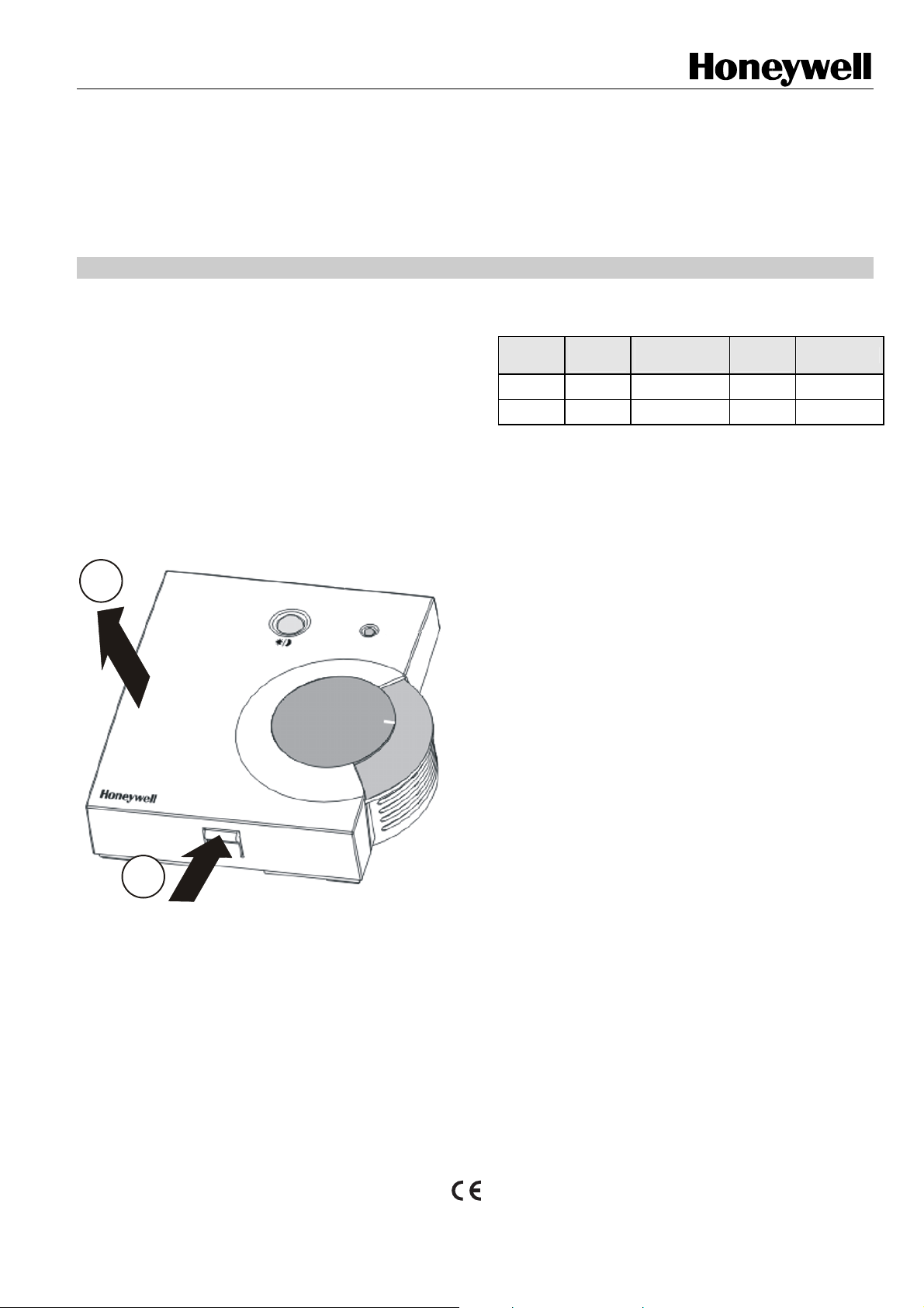
Removing Cover
The cover of the wall module is fixed in place using a tab
located on the underside of the unit; to remove the cover
from the subbase, see Fig. 1.
LIFT
2
1
PRESS
Fig. 1. Cover disassembly
FEATURES
Table 1. Features of the C7110C,D
C7110C
C7110D
CO2
sensor
3
3 3 3
space temp.
sensor
-- -- CO
setpoint
dial
LED
level
2
occupancy
INSTALLATION
The C7110D packages include two setpoint dials. By
default, the “Celsius Relative” type is mounted. This can be
easily replaced with the “Celsius Absolute” type by pulling
the one dial off and inserting the other one.
Mount the C7110C,D Wall Modules on an inside wall
approx. 54 in. (1.3 m) from the floor (or in the specified
location) to allow exposure to the average zone temperature.
NOTE: Maintain a mounting clearance of approx. 4 in.
(10 cm) to the left-hand side of the module in
order to allow a free airflow for the temperature
sensor and accessibility of the setpoint dial.
Do not mount the wall modules on an outside wall,
on a wall containing water pipes, or near air ducts.
Avoid locations exposed to discharge air from
registers or radiation from lights, appliances, or
the sun.
Keep wiring at least one ft (305 mm) away from
large inductive loads such as motors, line starters,
lighting ballasts, and large power distribution
panels.
Run wall module wiring separately from 50 Vac or
greater power wiring.
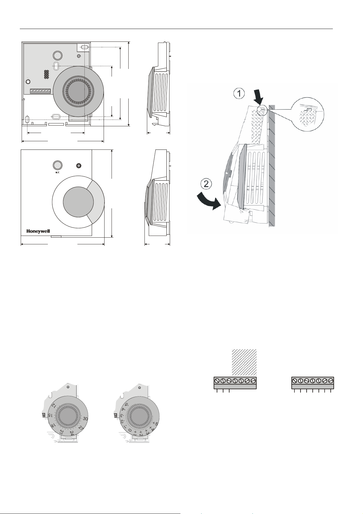
The wall modules can be mounted on a 60-mm wall outlet
box using No. 6 (3.5-mm) screws or on a wall (see Fig. 2).
When mounting directly on a wall, use the type of screws
appropriate for the wall material.
See Fig. 2 for C7110C,D mounting dimensions.
® U.S. Registered Trademark EN1B-0257GE51 R1105C
Copyright © 2005 Honeywell Inc. • All Rights Reserved
Page 2
C7110C,D WALL MODULES
Fig. 3. Mounting position of setpoint dial
7. If the dial does not have the correct position, pull the
dial off again and reinsert it with the correct orientation.
8. Remount the cover as depicted in Fig. 4 and make sure
that the tab on the underside engages.
2-3/8 (60)4-1/8 (104)
4 (100)
3-7/16 (86)
1-1/16
(27)
1-3/16
(30)
34567
12
2-11/16 (68)
3-7/8 (97)
3-15/16 (99)
Fig. 2. C7110C,D bore-holes, dimensions in in. (mm)
Mounting Procedure
1. Disassemble the cover as is shown in Fig. 1.
2. Remove the setpoint dial by pulling it off.
3. a) Mount the wall module onto the wall outlet box,
or
b) bore wall holes as is specified in Fig. 2 and mount
the wall module with appropriate screws.
4. Connect the wires to the terminal block according to the
specifications in section "Wiring".
5. Insert the setpoint dial and turn it clockwise as far as
possible.
6. Make sure that the dial's position is such that the 30
(Celsius absolute scale) or the +5 (Celsius relative
scale) point to the right-hand side of the wall module
(see Fig. 3).
Fig. 4. Mounting cover of C7110C,D Wall Modules
Wiring
Attach the wires from the device sensor terminals to the
appropriate wall module terminals. See Fig. 5.
IMPORTANT
Screw type terminal blocks are designed to accept
no more than one 16 AWG (1.5 mm2) conductor.
Wire the terminal blocks as follows:
1. Strip 3/16 in. (5 mm) of insulation from the conductor.
2. Insert the wire in the required terminal location and
tighten the screw to complete the termination.
3. Verify wall module wiring with Fig. 5.
C7110C
1:COM
2:CO23:IN 24V
4:TEMP
5:SET PT
6:LED
C7110D
7:BYPASS
1:COM
2:CO23:IN 24V
4:TEMP
5:SET PT
6:LED
7:BYPASS
EN1B-0257GE51 R1105C
Fig. 5. Wiring diagrams for C7110C,D Wall Modules
2
Page 3

ACCESSORIES
j
T7460-LONJACK
The T7460-LONJACK is a small board and allows easy
access to L
must be already connected, in compliance with the max.
cable lengths set forth by the L
L
ONWORKS network via a LONWORKS bus cable). Via an
additional 3.5 mm jack plug on the board, a PC connection
can be established.
Order quantity: set with 5 pieces
ONWORKS via the wall module (the wall module
ONWORKS Guidelines, to the
C7110C,D WALL MODULES
T7460-LIMITER
The T7460-LIMITER can be used to limit the setpoint dial
to within a narrower range.
Put the limiters approximately opposite the setpoints you
want to adjust. In the following example, the setpoint limits
are at about 18 and 27 °C.
Order quantity: set of 100 pieces
Limiter 1
LonWorks
connection
terminals
PC con-
nection
(3.5 mm
ack plug)
Fig 9. T7460-LONJACK
Mounting
Remove the setpoint dial and insert the T7460-LONJACK
as shown in the following:
Limiter 2
2
1
1
5
2
1
Setpoint Limit 1
Fig 11. Mounting T7460-LIMITER(S)
UIP Software Module
The default settings of the C71101C,D can be reconfigured
using the UIP software module, which can be downloaded
free of charge from the Honeywell Plug-In Download Area
at the following URL:
http://web.ge51.honeywell.de/productsupport/website/Sensors.htm
In order to use the UIP software module to reconfigure the
C71101C,D Wall Modules, you must first connect the Wall
Module's 4-prong male connector (located to the right of
the terminal block on the PCB) to your PC via the HDI 10
Interface Cable, available as an accessory (see below).
0
3
2
7
Setpoint Limit 2
Fig. 6. 4-prong male connector (accessible after
removing cover)
NOTE: Only one instance of the UIP software may be
active on your PC at a time.
HDI 10 Interface Cable
Accessory for connecting the C71101C,D Wall Module to
Fig 10. Mounting T7460-LONJACK
your PC for the purpose of configuring the Wall Module
using the previously-downloaded UIP Software Module.
3
EN1B-0257GE51 R1105C
Page 4

C7110C,D WALL MODULES
SPECIFICATIONS
Mounting options: The wall modules can be mounted on
a 60 mm diameter junction box or directly on a wall.
Dimensions (H ± W ± D): 4-1/8 ± 3-15/16 ± 1-3/16 in.
(104 ± 99 ± 30 mm).
Operating Temperature: 43...104°F (6...40°C).
Shipping Temperature: -40...+150°F (-40...+65°C).
Relative Humidity: 5...95% non-condensing.
Measurement range: 0...2000 ppm (factory default);
adjustable to 3000 ppm using UIP software kit
Accuracy: ±100 ppm or 7% (whichever is greater)
Elevation (Pressure) correction: Add 0.13% of reading
per mm Hg below 760 mm Hg (on-board correction, userset using UIP software)
Response time, 0...90%: < 5 min
Warm-up time: < 2 min
Agency certification: FCC Part 15 Class B, CE, California
Energy Commission
Power:
• 18...30 Vac rms, 50/60 Hz (half-wave, rectified)
• 18...42 Vdc (polarity protected)
• 1.75 VA max. average power
• 2.75 VA peak power
Analog output (simultaneous): 0...10 Vdc (100 Ω output
impedance), 4...20 mA (external RL
= 500 Ω)
max
Manufactured for and on behalf of the Environmental and Combustion Controls Division of Honeywell Technologies Sàrl, Ecublens, Route du Bois 37, Switzerland by its Authorized Representative:
Automation and Control Solutions
Honeywell GmbH
Böblinger Straße 17
D-71101 Schönaich
Phone: (49) 7031 63701
Fax: (49) 7031 637493
http://europe.hbc.honeywell.com
Subject to change without notice. Printed in Germany
EN1B-0257GE51 R1105C
ISO9001
 Loading...