

Page 1
HONEYWELL EXCEL 5000 OPEN SYSTEM
FEATURES
• Mountable on 2.36 in. (60 mm) wall outlet box or
• With setpoint adjustment dial (Celsius relative or
C7110C1001/D1009
WALL MODULES
SPECIFICATION DATA
directly on a wall.
Celsius absolute scale) (C7110D1009, only).
GENERAL
The C7110C1001 and C7110D1009 are wall modules
which can be directly wired to Honeywell Excel 600, 500,
100, 50, and 20 Controllers.
Please refer to the technical specifications of the individual
controllers in order to determine their suitability for use in
conjunction with a given wall module application.
• With CO
level (C7110C1001) or occupancy (C7110D1009).
• With space temperature sensor (C7110D1009, only).
• With occupancy bypass button (C7110D1009, only).
• Locking cover on all models.
• Operating range 43 to 104°F (6 to 40°C).
• CE approved.
• IP 30 housing.
• Compact.
• Configurable using Honeywell's free UIP software
module (see section "Specifications" on page 4).
• Self-calibrating.
• CO
binary output.
• Life-span: min. 13 years.
sensor and LED indicating either CO2
2
output (pin 2) configurable as an analog or
2
DESCRIPTION
The C7110C1001 is equipped with a CO2 sensor. The
C7110D1009 is equipped with both a CO
space temperature sensor.
The C7110D1009 also features a setpoint adjustment dial.
By default, the “Celsius Relative” type (-5 to +5) is
mounted, but can be easily replaced with the “Celsius
Absolute” type (12 to 30°C).
The C7110C1001 features a CO
The C7110D1009 features an occupancy bypass button
and an occupancy LED.
level LED.
2
sensor and a
2
® U.S. Registered Trademark
Copyright © 2009 Honeywell Inc. • All Rights Reserved EN0B-0457GE51 R0309
Page 2
C7110C,D WALL MODULES
F
t
r
resis
t
o
hms
SPECIFICATIONS
Table 1. C71100C1001 and C71100D1009 Wall Module models
model no.
C7110C1001 --
C7110D1009
NOTE: For wall module settings and wiring diagrams, refer
to the C7110C,D Installation Instructions (product
literature no.: EN1B-0257GE51). Some features may
not be available with all controllers (see Table 1).
Construction:
Two-piece construction, a cover and an internally wired subbase. Field wiring 16 to 22 AWG (1.5 to 0.34 mm
to a terminal block on the PCB.
Temperature Sensor Operating Range:
43…104°F (6…40°C).
space temp.
sensor
3 3
Temperature Sensor Accuracy
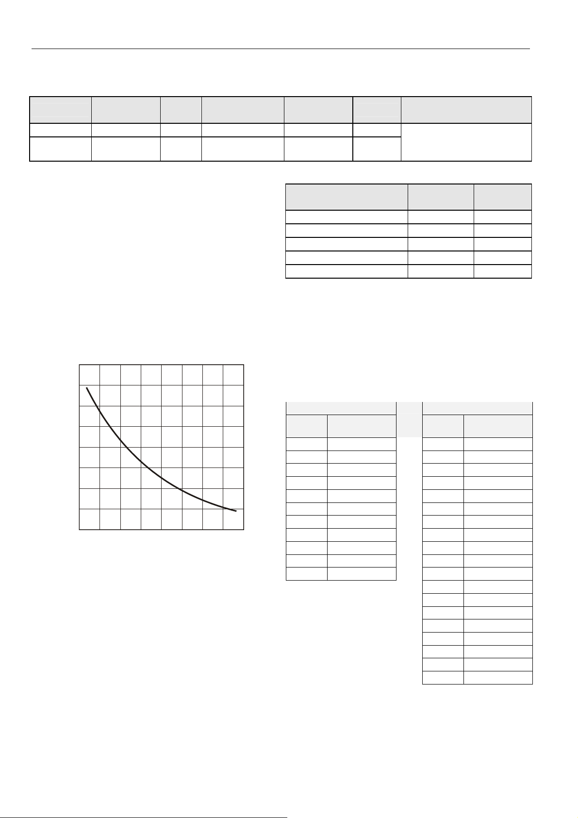
20 kΩ Sensor:
The C7110D1009 is equipped with a 20 kΩ NTC temperature
sensor following a specific temperature-resistance curve (see
Fig. 1).
80 K
70 K
)
60 K
50 K
ance (
40 K
30 K
ical
20 K
elec
10 K
30
40 50 60 70 80 90 100 110
0 10 20 30 40
temperature (degrees)
Fig. 1. Temperature vs. resistance for 20 kΩ sensor
Honeywell controllers used with these Wall Modules employ
an algorithm that provides readings close to the actual
temperature. Table 2 summarizes the sensor accuracy for
normal operating temperatures.
CO2
sensor
3
setpoint
adjustment dial
-- -- CO2 level
12 to 30°C (abs.)
± 5 K (rel.)
2
) connects
°
°C
occupancy
bypass button
3
Table 2. Temperature sensor accuracy
ambient temperature
°F (°C)
60 (15.5) ±0.52 (±0.29) 31543
65 (18.3) ±0.49 (±0.27) 27511
70 (21.1) ±0.48 (±0.27) 24047
80 (26.7) ±0.49 (±0.27) 18490
85 (29.5) ±0.52 (±0.29) 16264
C7110D Setpoint Adjustment:
In the case of the C7110D, which is equipped with a setpoint
adjustment dial, depending on the type of dial in use, the
corresponding controller must be set for either the relative or
the absolute scale. The relation between setpoint and
resistance is given in Table 3. Accuracy of resistance is:
• ±5% in middle position, e.g. 5225 Ω to 5775 Ω
• ±10% in end position, e.g. 9450 Ω to 11550 Ω.
Table 3. Setpoint values versus resistances
relative scale (Kelvin) absolute scale (°C)
setpoint
-5 9574.0 12 9958.0
-4 8759.2 13 9468.7
-3 7944.4 14 8979.3
-2 7129.6 15 8490.0
-1 6314.8 16 8000.7
resistance (Ω)
0 5500.0 17 7511.3
1 4685.2 18 7022.0
2 3870.4 19 6532.7
3 3055.6 20 6043.3
4 2240.8 21 5554.0
5 1426.0 22 5064.7
23 4575.3
24 4086.0
25 3596.7
26 3107.3
27 2618.0
28 2128.7
29 1639.3
30 1150.0
LED
occupancy
nominal
compatible with the following
Honeywell controllers
Excel 600, 500, 100, 50, and 20
max. error
°F (°C)
setpoint
nominal re-
sistance (Ω)
nominal
resistance (Ω)
EN0B-0457GE51 R0309
2
Page 3

C7110C,D WALL MODULES
Configuration of Pin 2
The CO2 output (pin 2) of the C7110C/D Wall Modules can be
configured (using the UIP software module – see also section
"UIP Software Module" on page 4).
In order to use the UIP software module to reconfigure pin 2,
you must first connect the Wall Module's four-prong male
connector (located to the right of the terminal block on the
PCB after removing the cover; see Fig. 2) to one of your PC's
serial communication ports; this is done using the HDI 10
Interface Cable, available as an accessory (see section "HDI
10 Interface Cable" on page 4).
Fig. 2. Four-prong male connector
Upon then starting the UIP software program (only one
instance of which may be active on your PC at a time), a
window will appear in which you must specify to which of your
PC's serial communication port you have connected the fourprong male connector.
Following this, a second window (the "configuration window")
will appear in which you can configure pin 2 in a variety of
fashions (see following sub-sections).
NOTE: If your PC is not equipped with a mouse or track ball,
you can navigate forwards by pressing your PC's
TAB key, and backwards by pressing SHIFT + TAB.
Further, you can check/uncheck selections using the
SPACE key
Voltage Output
In the left-hand area (labeled "Voltage Output") of the configuration window, you can select either
• the "Scaled Output" checkbox (default setting) or
• the "Relay Output" checkbox.
Scaled Output (Analog Output)
If you select the "Scaled Output" checkbox, pin 2 will deliver
analog output. In this case, you can then configure a
measuring range of either
• 0 ppm to 2000 ppm or
• 0 ppm to 3000 ppm.
You can then also configure pin 2 for either
• 0...10 V analog output or
• 2...10 V analog output.
output
NOTE: After having selected "Scaled Output," the CO2 level
LED of the C7110C is disabled.
Relay Output (Digital Output)
If you select the "Relay Output" checkbox, pin 2 will deliver
digital output. In this case, you can then configure a
"Threshold Level (PPM)" of any value between 0 and 2000
("600" is the default setting), and a "Hysteresis (PPM)" of any
value between 1 ppm and 50% of the "Threshold Level
(PPM)" ("100" is the default setting).
See Fig. 4 for the resultant output of pin 2 and (in the case of
the C7110C) the corresponding behavior of the CO
level
2
LED.
output
THRESHOLD LEVEL (ppm)
(GREEN TO YELLOW)
10 V
0 V
500
Hysteresis (PPM)
600
CO2 (ppm)
Fig. 4. Relay output (digital) of pin 2
In the case of the C7110C, the resultant output is applied to
the LED input (pin 6). The CO
level LED will thus glow green
2
below and yellow above the threshold level.
Occupancy Bypass Button / Occupancy LED
(C7110D1009, only)
Overrides can result e.g. from the controller's own internal
programming. In the case of the C7110D1009, overrides can
also result from pressing the occupancy bypass button (see
also Fig. 5).
occupancy
bypass button
occupancy
LED
10 V
Fig. 5. C7110D1009
The functionality of the occupancy bypass button and the
resultant behavior of the occupancy LED are dependent upon
the given controller. Please refer to the Technical Literature
pertaining to the specific controller
0/2 V
CO2 (ppm)
Fig. 3. Scaled output (analog) of pin 2
EN0B-0457GE51 R0309
3
Page 4

C7110C,D WALL MODULES
With Excel 600/500/100/50/20 Controllers
All Excel 600, 500, 100, 50, and 20 Controllers are fully programmable. The application engineer/programmer can
program the occupancy bypass button and the occupancy
LED to operate in any manner desired.
The bypass (override) output pin (pin 7 of the C7110D1009) is
a normally-open, digital tactile switch.
Contact your local Honeywell distributor for further details.
SPECIFICATIONS
Mounting options: The wall modules can be mounted on a
60 mm diameter junction box or directly on a wall.
Dimensions (H ± W ± D): 4-1/8 ± 3-15/16 ± 1-3/16 in.
(104 ± 99 ± 30 mm).
Operating Temperature: 43...104°F (6...40°C).
Shipping Temperature: -40...+150°F (-40...+65°C).
Relative Humidity: 5...95%, non-condensing.
Measurement range: 0...2000 ppm (factory default);
adjustable to 3000 ppm using UIP software kit
Accuracy: ±100 ppm or 7% (whichever is greater)
Elevation (Pressure) correction: Add 0.13% of reading per
mm Hg below 760 mm Hg (on-board correction, user-set
using UIP software)
Response time, 0...90%: < 5 min
Warm-up time: < 2 min
Agency certification: FCC Part 15 Class B, CE, California
Energy Commission
Power:
• 18...30 Vac rms, 50/60 Hz (half-wave, rectified)
• 18...42 Vdc (polarity protected)
• 1.75 VA max. average power
• 2.75 VA peak power
Analog output (simultaneous): 0...10 Vdc (100 Ω output
impedance), 4...20 mA (external RL
= 500 Ω)
max
ACCESSORIES
For mounting the following accessories, please refer to the
C7110C,D Installation Instructions (product literature no.:
EN1B-0257GE51).
T7460-LONJACK
The T7460-LONJACK is a small board and allows easy
access to L
must be already connected, in compliance with the max.
cable lengths set forth by the L
L
ONWORKS network via a LONWORKS bus cable). Via an
additional 3.5 mm jack plug on the board, a PC connection
can be established.
Order quantity: set of 5 pieces
T7460-LIMITER
The T7460-LIMITER (for the C7110D1009, only) can be used
to limit the setpoint dial to within a narrower range.
Order quantity: set of 100 pieces
UIP Software Module
The default settings of the C7110C,D can be reconfigured
using the UIP software module, which can be downloaded
free of charge from the Honeywell Plug-In Download Area at
the following URL:
http://web.ge51.honeywell.de/productsupport/website/Sensors.htm
HDI 10 Interface Cable
Accessory for connecting the C7110C,D Wall Module to your
PC for the purpose of configuring the Wall Module using the
previously-downloaded UIP Software Module.
ONWORKS via the wall module (the wall module
ONWORKS Guidelines, to the
Manufactured for and on behalf of the Environmental and Combustion Controls Division of Honeywell Technologies Sàrl, Rolle, Z.A. La Pièce 16, Switzerland by its Authorized Representative:
Automation and Control Solutions
Honeywell GmbH
Böblinger Strasse 17
71101 Schönaich
Germany
Phone: (49) 7031 63701
Fax: (49) 7031 637493
http://ecc.emea.honeywell.com
Subject to change without notice. Printed in Germany
EN0B-0457GE51 R0309
 Loading...