

Page 1
GENERAL
The C7110A Room Air Quality Sensor is suitable for
measuring air quality in rooms, offices, and production bays.
This mixed gas sensor can be used to control ventilation
plants. It detects unpleasant odors, tobacco smoke, and
vapors emitted by such materials as furniture, carpets, paint,
glue, etc. As proven in practice, this device detects those
substances typically present in air having a poor quality,
some of which may otherwise go undetected by room
occupants, themselves. This sensor has proven itself in
numerous applications over many years.
NOTE: The mixed gas sensor does not measure or indicate
the concentration of individual gases, and thus
cannot be used for the monitoring or control of
specific substances.
Models
Order Number Description Output
C7110A1005 Room Air Quality Sensor 0...10Vdc
C7110A
ROOM AIR QUALITY SENSOR
SPECIFICATION DATA & INSTALLATION INSTRUCTIONS
FEATURES
• Measurement of a variety of air quality factors
• Output signal: 0...10 Vdc (adjusted using potentio-
meter)
• Adjustable output offset
• Easy installation and wiring connection
SPECIFICATION
Supply voltage 15...30 Vdc / 24 Vac (+/-10%)
Power consumption < 1 W
Output signal 0...10 Vdc (increases as air
quality worsens); adjustable
Max. load at output 5 kOhm
Weight /Dimensions approx. 125 g / see page 3
Electrical connection Screw terminal block for
Air Quality Sensor
Sensitivity/Linearity see Fig. 1 on page 2
Dynamic behavior see Fig. 6 on page 4
Ambient Limits
Transport/storage temp. -30...+60 °C (-22...+140 °F
Operating temperature 0...+50 °C (+32...+122 °F)
Humidity 5...95%rh, non-condensing
Safety
Protection class II as per EN60730-1
Protection standard IP30 as per EN60529
Flame retardant V0 as per UL94 Plastic ABS
using potentiometer
conductors up to 1.5 mm²
)
® U.S. Registered Trademark EN0B-0295GE51 R0409
Copyright © 2009 Honeywell Inc. • All rights reserved
Page 2
C7110A ROOM AIR QUALITY SENSOR
R
R
FUNCTION
The electrical conductivity of a heated tin-dioxide semiconductor sensor varies in proportion to the number of
molecules of the reducing agents. This leads to a voltage at
the measuring element which is amplified to an output
voltage of 0 to 10 Vdc.
The following particles and gases can be detected:
cigarette smoke, hydrogen, carbon monoxide, ethanol,
ammonia, etc.
In contrast to CO
2 sensors, which selectively measure the
concentration of only one type of gas, a mixed gas sensor
is a broadband detector, i.e. the sensor signal does not
indicate the type of gas or its concentration in ppm (parts
per million). The complex and constantly changing composition of room air makes it necessary to perform
broadband air quality measurement.
1
methane
/
gas air
0.1
0.01
1
ammonia
acetic acid
CO
ethanol
hydrogen
ppm
100010010
Fig. 1 Sensor sensitivity with different gases
INSTALLATION
Wiring
All wiring must comply with local electrical codes and
ordinances or as specified on installation wiring diagrams.
Wall module wiring can be sized from 16 to 22 AWG (1.5 to
0.34 mm
length of wire from a device to a wall module is 1000 ft (305
m). Twisted pair wire is recommended for wire runs longer
than 100 ft (30.5 m).
Keep wiring at least one ft (305 mm) away from large
inductive loads such as motors, line starters, lighting
ballast, and large power distribution panels.
Run wall module wiring separately from 50 Vac or greater
power wiring.
Positioning
To avoid falsifying the measuring results, the device should
be installed at sites at which typical air quality prevails.
Direct exposure to sunlight and drafts should be avoided.
If the device is mounted on a standard flush box, the end of
the installation tube in the flush box must be sealed so to
avoid any draft in the tube falsifying the measuring result.
2
), depending on the application. The maximum
Maintain a mounting clearance of approx. 4 in. (10 cm) to
the right-hand side of the module in order to allow free
airflow to the air quality sensor.
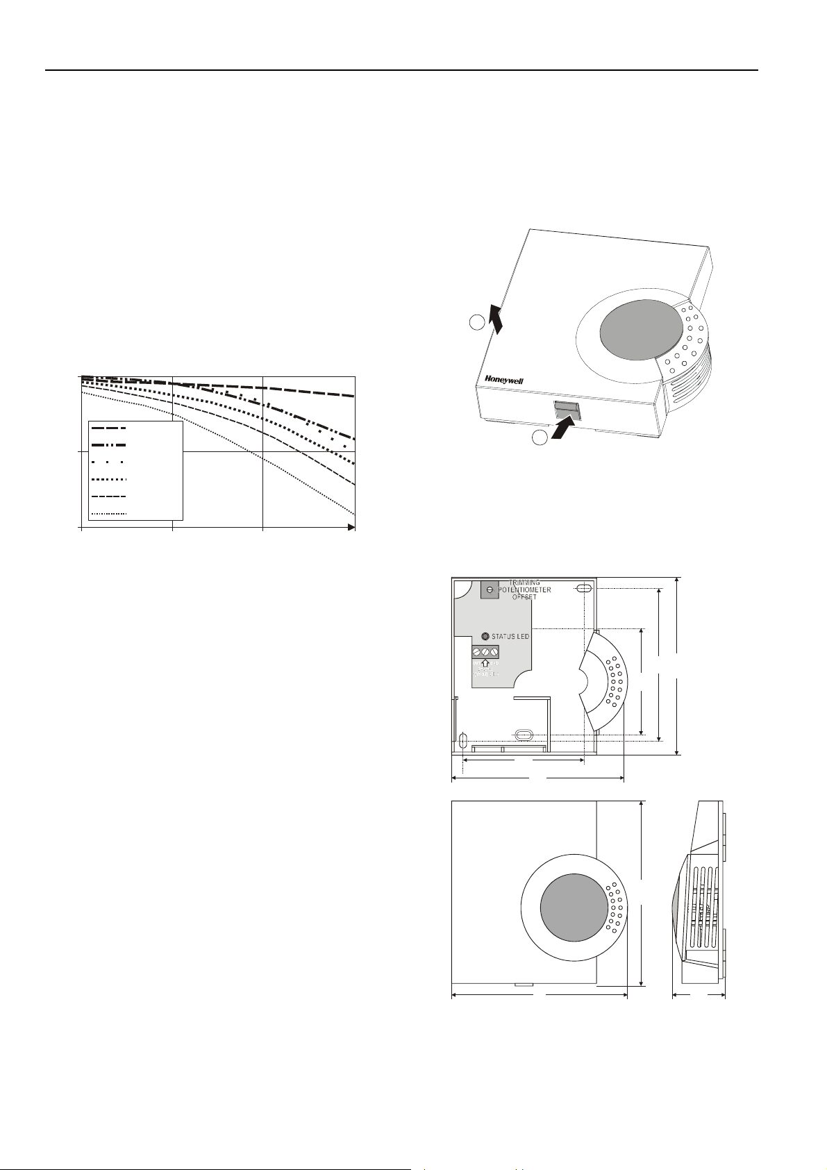
Mounting
1. The cover of the air quality sensor is fixed by a tab
on the underside of the unit; to disassemble the
cover and the sub-base, see Fig. 2.
LIFT
2
1
PRESS
Fig. 2 Cover disassembly
2. a) Mount the sensor onto the wall outlet box,
or
b) bore wall holes as specified in Fig. 3 and mount
the wall module with appropriate screws.
60
68
97
104
99 30
Fig. 3 Dimensions and mounting holes (mm)
86
100
EN0B-0295GE51 R0409 2
Page 3

IMPORTANT
Screw-type terminal blocks are designed to accept
no more than one 16 AWG (1.5 mm
3. Connect the wires to the terminal block as follows:
a) Strip 3/16 in. (5 mm) of insulation from the
conductor.
b) Insert the wire in the required terminal location
(see Fig. 5) and tighten the screw to complete
the termination.
4. Remount the cover as shown in Fig. 4 and make
sure that the tab on the underside engages.
5. Adjust the trimming potentiometer offset (see
section “Adjusting the Trimming Potentiometer
Offset”).
6. The sensor is now operational. When the air quality
deteriorates, the voltage of the output signal will
rise.
2
) conductor.
1
2
Fig. 4 Cover assembly
Adjusting the Trimming Potentiometer
Offset
After mounting the device, the output signal should be
adjusted in accordance with expected ambient conditions
and individual preferences.
The output signal is adjusted using the trimming potentiometer located on the sensor board (see Fig. 5). The offset
of the output signal is increased or lowered by means of
this potentiometer.
C7110A ROOM AIR QUALITY SENSOR
OUT GND
24V/AC
+(15-30) V/DC
Fig. 5 Wiring Connection and Trimming Potentiometer
• Turning the potentiometer counterclockwise decreases
the output signal.
• Turning the potentiometer clockwise increases the
output signal.
The sensor cannot distinguish pleasant from unpleasant
smells. The final adjustment whether air quality is
satisfactory or not must be made by the persons living or
working in the room. Moreover, various air compositions
are occurring in different rooms.
Thus, the default (factory) setting of the setpoint is
provisional, only. The setpoint must be optimized to
correspond to the subjective feelings of the room
occupants.
Adjustment Procedure:
1. Connect sensor and switch operating voltage on.
2. Ensure good air conditions close to the sensor (by
means of ventilation, etc.).
3. After approx. 30 minutes of operation, one must
verify the output signal. The voltage level should lie
in the range 1…3 V. Please correct an excessively
high or excessively low voltage level using the
trimming potentiometer: The potentiometer should
be turned to counterclockwise until the red status
LED is almost extinguished. The output signal will
then amount to approx. 0.7 V.
NOTE: The red status LED is located on the sensor
board, visible when the cover has been removed
(see Fig. 5) which indicates the device's operating
status. The brightness of the red status LED is
proportional to 0..10 V output for reference.
3 EN0B-0295GE51 R0409
Page 4

C7110A ROOM AIR QUALITY SENSOR
v
oltag
mV)
EXAMPLE OF DYNAMIC BEHAVIOR
Fig. 6 shows the dynamic characteristics of the air quality
sensor, monitored during test measurements in a sample
room. This voltage diagram as a function of different
occupancy conditions is only an example and must be
proven for other ambient conditions.
10000
9000
8000
7000
10000
6000
e (
5000
4000
3000
2000
1000
0
0 50 100
time (minutes)
ROOM UNOCCUPIED,
IDLING.
AIR QUALITY SENSOR
ROOM OCCUPIED
ROOM OCCUPIED
BY TWO PERSONS.
ROOM OCCUPIED
(INCL. 1 SMOKING).
BY THREE PERSONS.
BY THREE PERSONS.
ROOM OCCUPIED BY 3
WINDOW FAN
SWITCHED ON.
ALL THREE PERSONS
HAVE VACATED ROOM.
ROOM UNOCCUPIED,
Fig. 6 Dynamic behavior of Room Air Quality Sensor
IDLING.
AIR QUALITY SENSOR
Manufactured for and on behalf of the Environmental and Combustion Controls Division of Honeywell Technologies Sàrl, Rolle, Z.A. La Pièce 16, Switzerland by its Authorized Representative:
Automation and Control Solutions
Honeywell GmbH
Böblinger Strasse 17
71101 Schönaich, Germany
Phone: (49) 7031 63701
Fax: (49) 7031 637493
http://ecc.emea.honeywell.com
Subject to change without notice. Printed in Germany
EN0B-0295GE51 R0409
 Loading...