

Page 1
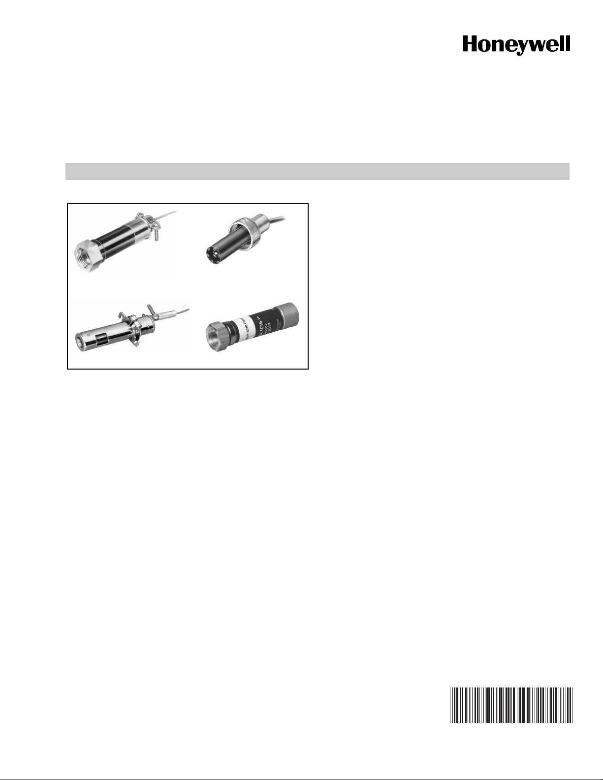
C7027A, C7035A, C7044A, C7927A
Minipeeper® Ultraviolet Flame Detectors
PRODUCT DATA
• C7927A is used with only the R7851B Flame Amplifier
and the 7800 SERIES controls.
• C7044A may also be used with the following 50 Hz
Honeywell combustion controls/amplifiers:
— R4341/R7323
C7027A C7035A
C7044A C7927A
APPLICATION
The C7027A, C7035A, C7044A and C7927A Minipeeper®
Ultraviolet Flame Detectors detect the ultraviolet radiation
emitted by combustion flames. The flame detectors are used
with Honeywell flame safeguard controls to provide flame
supervision for gas, oil, or combination gas-oil burners.
FEATURES
• C7027A, C7035A, and C7044A Flame Detectors are
used with RA890G devices or R7249A, R7290A,
R7749B and R7849A,B Amplifiers and the appropriate
Honeywell controls.
— R4343/R7323
— R4344/R7323
• C7027A/C7927A has an integral collar threaded
(internal 1/2-14 NPSM) for mounting on a one-half-inch
sight pipe.
• C7035A has an integral collar threaded (internal
1-11-1/2 NPSM) for mounting on a one-inch sight pipe.
• C7035A housing meets Underwriters Laboratories Inc.
requirements for rain tightness and complies with
NEMA enclosure standards, types 4 and 4X.
• C7044A mounts with a two screw bracket. The UV
sensor tube is enclosed in a stainless steel housing.
• C7044A has the capability of side or end viewing in
flame monitoring applications.
• Because of their compact size, the C7027A and
C7044A are particularly suitable for blast tube
mounting.
• Properly installed, the C7027A, C7035A and C7927 are
pressure rated for 5 psi.
• C7035A ultraviolet radiation sensor tube is field
replaceable.
• Two C7027A, C7035A or C7044A Flame Detectors can
be wired in parallel for difficult flame sighting
installations. (C7927cannot be used in parallel.)
• C7927A, C7027A1049, C7027A1064, C7027A1072 come
with 1/2-in. spud connection for electrical wiring.
Contents
Application ........................................................................ 1
Features ........................................................................... 1
Specifications ................................................................... 2
Ordering Information ........................................................ 2
Wiring (All Models—Fig. 9) ............................................... 8
Adjustments and Checkout .............................................. 9
Troubleshooting ................................................................ 12
Maintenance ..................................................................... 12
60-2026-13
Page 2
C7027A, C7035A, C7044A, C7927A MINIPEEPER® ULTRAVIOLET FLAME DETECTORS
SPECIFICATIONS
4 (102)
3-1/2 (89)
COLLAR WITH 1/2-14 NPSM
INTERNAL THREADS
1
C7027A1064 HAS 24 FOOT (7.32 METER) LEADWIRES.
C7027A1114 HAS 44 IN. (1.118 M) LEADWIRES WITH
22 IN. (558 MM) FLEXIBLE CONDUIT.
2
MODELS AVAILABLE WITH SPUD CONNECTOR (1/2-14 NPSM INTERNAL
THREADS) INSTEAD OF CLAMP TYPE CONNECTOR.
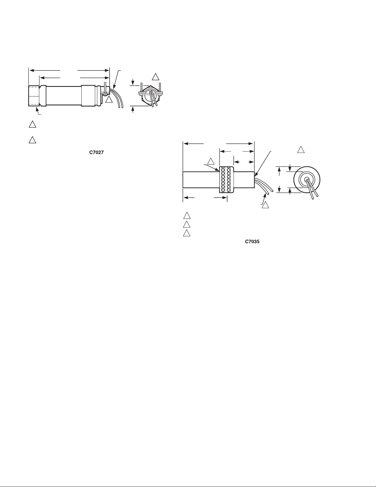
Fig. 1. Installation dimensions of C7027A in in. (mm).
C7027A Minipeeper® Ultraviolet Flame Detector:
Ambient Operating Temperature Ratings: 0°F to 215°F
(-18°C to 102°C), or -40°F to 215°F (-40°C to +102°C),
depending on model.
Maximum Pressure Rating: 5 psi (34.5 kPa).
Mounting: Collar with 1/2-14 NPSM internal threads for
mounting on a 1/2 in. sight pipe.
Wiring Connections: Two 8 ft (2.44 m), color-coded,
NEC Class 1 leadwires, rated for 221°F (105°C).
(C7027A1064 has 24 ft [7.32 m] leadwires.) Rear of
detector has a clamp type connector for 1/2 in. flexible
metallic conduit. (Models are available with 1/2 in.
internally threaded spud connector instead of the clamp).
C7027A1114 has 44 in. (1.118 m) leadwires and 22 in. (558
mm) flexible conduit.
8 FOOT (2.44 METER)
LEADWIRES (2)
2
1-1/16
(27)
1
M1943F
Dimensions: See Fig. 1.
Replacement Part: 129685 Flange Gasket.
NOTE: The ultraviolet radiation sensing tube is not field
replaceable.
Accessory:
136733 Heat Block, laminated plastic, insulating the
flame detector from sight pipe temperatures up to
266°F (130°C), 1/2-14 NPSM external threads on one
end and 1/2-14 NPSM internal threads on the other end
(see Fig. 7). Included with C7027A1080.
390427B Bushing, for mounting to 3/8 in. sight pipe. Included
with C7027A1080.
4-1/8 (105)
31/32
(25)
2
M1945D
COLLAR WITH
1 - 1-1/2 NPSM
INTERNAL
THREADS
INSERTION DEPTH
DIN APPROVED C7035A1064 HAS 1-11 BSP.P1 INTERNAL MOUNTING THREADS.
1
DIN APPROVED C7035A1064 HAS 1/2-14 BSP-F INTERNAL MOUNTING THREADS.
2
C7035A1056 HAS 12 FOOT (3.66 METER) LEADWIRES.
3
1
2-5/8 (67)
2 (51)
1-3/16
(30)
6 FOOT
[1.83 METER]
LEADWIRES (2)
1/2-14 NPSM
INTERNAL THREADS
1-1/2
(38)
3
Fig. 2. Installation dimensions of C7035A in in. (mm).
ORDERING INFORMATION
When purchasing replacement and modernization products from your TRADELINE® wholesaler or distributor, refer to the
TRADELINE® Catalog or price sheets for complete ordering number.
If you have additional questions, need further information, or would like to comment on our products or services, please write or
phone:
1. Your local Honeywell Automation and Control Products Sales Office (check white pages of your phone directory).
2. Honeywell Customer Care
1885 Douglas Drive North
Minneapolis, Minnesota 55422-4386
In Canada—Honeywell Limited/Honeywell Limitée, 35 Dynamic Drive, Toronto, Ontario M1V 4Z9.
International Sales and Service Offices in all principal cities of the world. Manufacturing in Australia, Canada, Finland, France,
Germany, Japan, Mexico, Netherlands, Spain, Taiwan, United Kingdom, U.S.A.
60-2026—13 2
Page 3
C7027A, C7035A, C7044A, C7927A MINIPEEPER® ULTRAVIOLET FLAME DETECTORS
C7035A Minipeeper® Ultraviolet Flame Detector:
Flame Detection: End viewing.
Ambient Operating Temperature Ratings: 0°F to 250°F
(-18°C to +121°C), or -40°F to 250°F (-40°C to +121°C),
depending on model.
Maximum Pressure Rating: 5 psi (34.5 kPa).
Mounting: Collar with 1-11-1/2 NPSM internal threads for
mounting on a 1 in. sight pipe. (The DIN approved
C7035A1064 has 1-11 BSP.P1 threads.)
Wiring Connections: Two 6 ft. (1.83 m), color-coded
NEC Class 1 leadwires rated for 302°F (150°C). One model
is available with 12 ft. (3.66 m) leadwires.
Rear of detector has 1/2-14 NPSM internal threads for
connecting to a conduit. The DIN-approved C7035A1064
has 1/2-14 BSP-F threads.
C7035A1056 has 12 ft (3.66 m) leadwires.
C7035A1080 leadwire is rated for 600°F (204°C).
6 FOOT [1.83 METER]
LEADWIRES (2)
Dimensions: See Fig. 2.
Replacement Parts:
129808 Flange Gasket.
129464M Ultraviolet Sensing Tube, 0°F to 250°F
(-18°C to +121°C).
129464N Ultraviolet Sensing Tube, -40°F to +250°F
(-40°C to 121°C).
C7027A, C7035A AND C7044:
Approvals:
Underwriters Laboratories Inc. listed: File No. MP268.
Canadian Standards Association certified:
Master Report LR 95329-1.
Factory Mutual approved.
Industrial Risk Insurers acceptable.
DIN approved models: C7027A1056, C7035A1049,
C7035A1064.
General Accessories:
118367A Swivel Mount; provides adjustable positioning of
the C7027A or C7035A.
204342 Ultraviolet mirror, 3/4 in. NPT.
105172C Seal off adapter, 3/4 in. NPT.
MOUNTING BRACKET
3/8
(10)
7/8
(22)
3-5/8 (92)
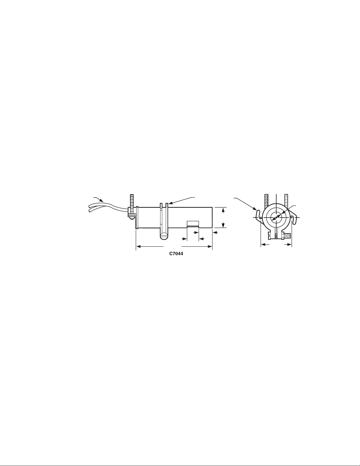
Fig. 3. Installation dimensions of C7044A in in. (mm).
C7044A Minipeeper® Ultraviolet Flame Detector:
Flame Detection: Housing has two openings to permit either
side or end viewing. Side viewing is 1/8 as sensitive as end
viewing.
Mounting: Bracket (included in 4074BVK Bag Assembly),
secured by two 8-32 RHIS (European M-4) screws (not
included).
Wiring Connections: Two 6 ft. (1.83 m) color-coded NEC
Class 1 leadwires. Rear of detector has a clamp type
connector for 1/2 in. flexible metallic conduit.
Dimensions: See Fig. 3.
9/16
(14)
1/2
(13)
1-27/64
(36)
M1944B
C7927A Minipeeper® Ultraviolet Flame Detector:
Ambient Operating Temperature Ratings:
C7927A1016: -40°F to +200°F
(-40°C to +93°C).
Storage Temperature Rating: -20°F to +120°F
(-28°C to +49°C).
Maximum Pressure Rating: 5 psi (34.5 kPa).
Mounting: Collar with 1/2-14 NPSM internal threads for
mounting on a 1/2 in. (13mm) sight pipe.
Wiring Connections: Two eight-foot (2.4 meter) color-coded
NEC Class 1 leadwires. Rear of detector has a clamp-type
connector for 1/2 in. (13mm) flexible metal conduit.
Dimensions: See Fig. 4.
Approvals:
Underwriters Laboratories Inc. (cUL), MP268, Volume 30 and 31.
Factory Mutual (FM) Approved, report number 3011020, June
26, 2002.
3 60-2026—13
Page 4

C7027A, C7035A, C7044A, C7927A MINIPEEPER® ULTRAVIOLET FLAME DETECTORS
3-7/8 (98)
3-3/8 (86)
COLLAR WITH 1/2-14 NPSM
INTERNAL THREADS
C7927A1016
Fig. 4. Installation dimensions of C7927A1016 in in. (mm).
INSTALLATION
When Installing This Product...
1. Read these instructions carefully. Failure to follow
them could damage the product or cause a hazardous
condition.
2. Check the ratings given in the instructions and on the
product to make sure the product is suitable for your
application.
3. Installer must be a trained, experienced, flame safeguard
control technician.
4. After installation is complete, check out product
operation as provided in these instructions.
Disconnect power supply before beginning installation to
prevent electrical shock and equipment damage. All wiring
must comply with applicable electrical codes, ordinances
and regulations. Use NEC Class 1 wiring.
8 FOOT (2.44 METER)
LEADWIRES (2)
SPUD CONNECTOR (1/2-14
NPSM INTERNAL THREADS)
IMPORTANT
Ultraviolet radiation sensing tubes have a life
expectancy of 40,000 hours of continuous use within
the flame detector's specified ambient temperature
and voltage ratings. Wearout of an ultraviolet
radiation sensing tube results in failure of the UV
sensor to properly discriminate between flame
conditions.
The C7027A, C7035A, C7044A and C7927 Flame
Detectors should only be used on burners that cycle
on/off or, in the absence of cycling, are periodically
checked for proper operation following the application
instructions provided by the equipment manufacturer.
Recommended industry standards for the frequency
of sensor checks, either through cycling (employing
safe-start check methods) or periodic maintenance. If
uncertain, FM guidelines suggest one burner cycle in
a 24-hour period.
(25)
1
M24714
Consult the equipment manufacturer or the governing
standard for recommendations about frequency of
checks.
Controls incorporating safe-start checks, and sensors
and controls employing constant check means are
available from Honeywell. See your Honeywell
representative for specific information.
60-2026—13 4
Page 5

C7027A, C7035A, C7044A, C7927A MINIPEEPER® ULTRAVIOLET FLAME DETECTORS
WARNING
Explosion Hazard and Electrical Shock Hazard.
Can cause serious injury, death or property
damage.
1. The C7027A, C7035A, C7044A and C7927 Flame
Detectors must be used with Honeywell flame
safeguard controls (primaries, programmers,
multiburner systems, and burner management
systems). Using with controls not manufactured by
Honeywell could result in unsafe conditions.
2. Disconnect power supply before beginning
installation to prevent electrical shock or equipment
damage, more than one disconnect may be
involved.
3. Read the installation instructions before starting the
installation.
4. All wiring must be NEC Class 1 (line voltage).
5. The flame detector must be positioned so that it
sights the flame and does not respond to the UV
radiation emitted by sparks generated by a spark
ignitor. The Q624A Solid-State Igniter may be useful
in difficult installations.
Other Radiation Sources Sensed By The UV Detector
Examples of radiation sources (other than flame) that could
actuate the detection system are:
1. Ultraviolet Sources:
a. Hot refractory above 2500°F (1371°C).
b. Spark.
c. Ignition transformers.
d. Welding arcs.
e. Lightning.
f. Gas lasers.
g. Sun lamps.
h. Germicidal lamps.
2. Gamma Ray and X-ray Sources:
a. Diffraction analyzers.
b. Electron microscopes.
c. Radiographic X-ray machines.
d. High voltage vacuum switches.
e. High voltage condensers.
f. Radiosotopes.
Except under unusual circumstances, none of these sources
except hot refractory and ignition spark would be present in or
near the combustion chamber.
Basic Requirements For Ultraviolet Detector Installations
All flames emit ultraviolet radiation, invisible to the human eye
but detected by the UV sensing tube. There are two important
factors in UV detector installation:
The detector must have a line-of-sight view of the flame.
The detector must not be exposed to other sources of
ultraviolet radiation, the most common being ignition spark.
Other sources are listed in the next section.
Because it is necessary for the detector to actually see the
flame, it is desirable to locate the detector as close to the flame
as physical arrangement and temperature restrictions permit.
Sighting requirements for different types of flame supervision
are:
1. Pilot flame only—Sighting must be along the axis of the
pilot flame. The smallest pilot flame that can be sighted
must be capable of igniting the main burner (see Pilot
Turndown Test, page 10).
2. Main flame only—Sighting must be at the most stable
part of the flame for all firing rates.
3. Pilot and main flame—Sighting must be at the junction of
both flames.
The detector may respond to hot refractory above 2500°F
(1371°C) if the refractory surface represents a significant
percentage of the field of view of the detector. If the
temperature of the hot refractory causes the flame relay
(in the flame safeguard control) to pull in, re-position the sight
pipe so the detector views a cooler area of the refractory.
Ignition spark is a source of ultraviolet radiation. When
installing the C7027A, C7035A, C7044A or C7927 Flame
Detector, make sure it does not respond to ignition spark (see
Ultraviolet Response Test, page 11.)
For C7027A, C7035, and C7044A applications whose
response to ignition spark cannot be avoided, the Q624A
Solid-State Ignition Transformer may eliminate the ignition
spark response. The Q624A, when properly installed, prevents
C7027A, C7035A and C7044A ignition spark response by
alternately activating the spark generator and the UV sensing
tube.
5 60-2026—13
Page 6
C7027A, C7035A, C7044A, C7927A MINIPEEPER® ULTRAVIOLET FLAME DETECTORS
Mounting a C7027A, C7927 or C7035A
Locate the Sight Pipe
The location of the sight pipe is the most critical part of the
installation. A black iron pipe is recommended. Do not use a
stainless steel or galvanized pipe because its internal surface
blackens with use as deposits from the combustion chamber
settle on it. Initially, its shiny internal surface reflects ultraviolet
radiation, which could result in a satisfactory flame signal, even
though the pipe may be improperly located. As it blackens, less
ultraviolet radiation is reflected and the flame signal may
become marginal.
Under optimum sighting conditions, the C7027A, C7927 and
C7035A Flame Detectors can detect most common gas and oil
combustion flames at a distance of six feet. The critical factors
in determining the flame-detector distance separation are the
optimized flame signal (current or voltage) and the flame
detector temperature. Other factors may be influential and are
associated with the specific installation. For minimum flame
signals, see Table 1 and for ambient operating temperatures,
refer to Specifications, page 2.
Use 1/2 in. pipe for a C7027 or C7927, and 1 in. pipe for
a C7035. Since no two situations are likely to be the same,
length and sighting angle of the pipe must be determined at the
time and place of installation. Generally, it is desirable
to have the sight pipe tilting downward to prevent soot or dirt
buildup.
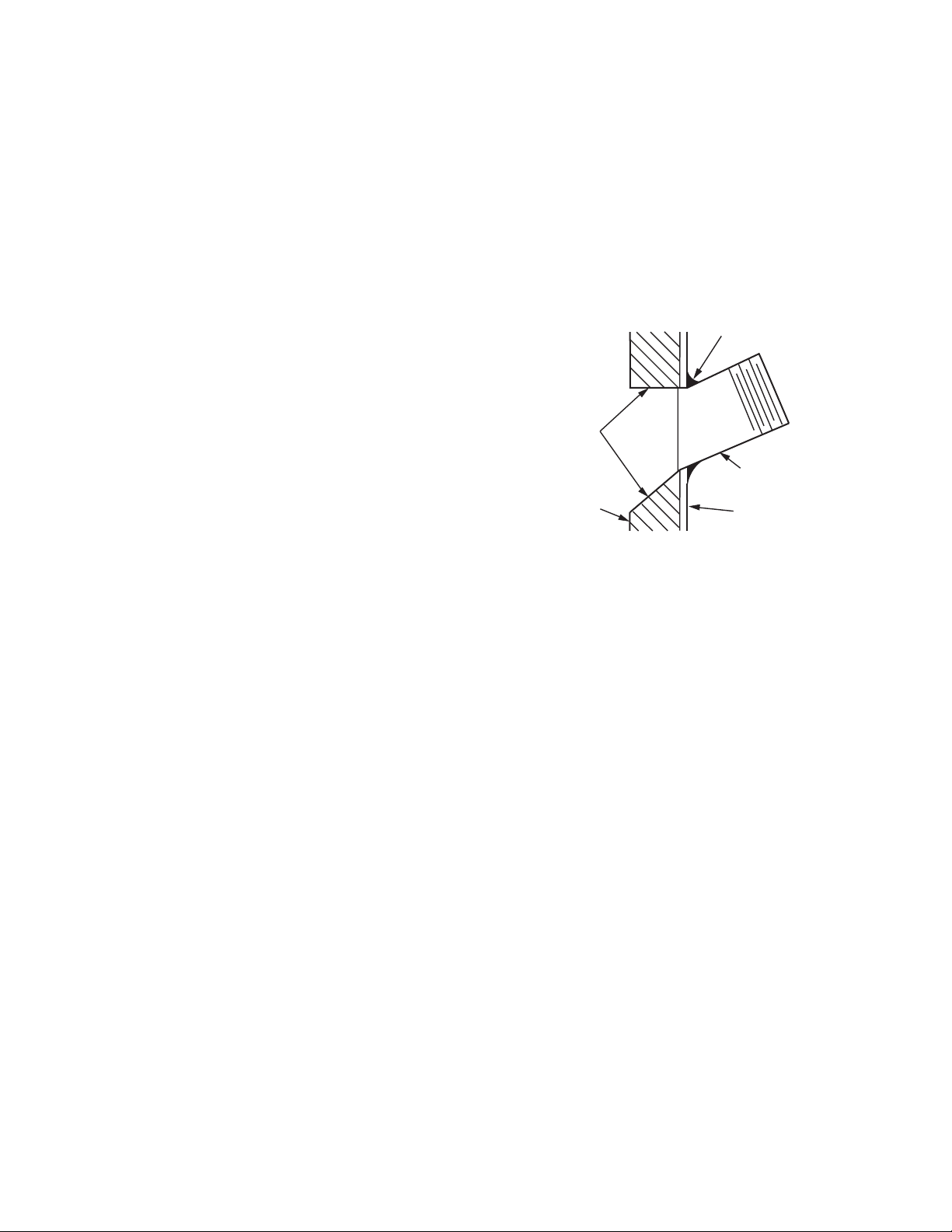
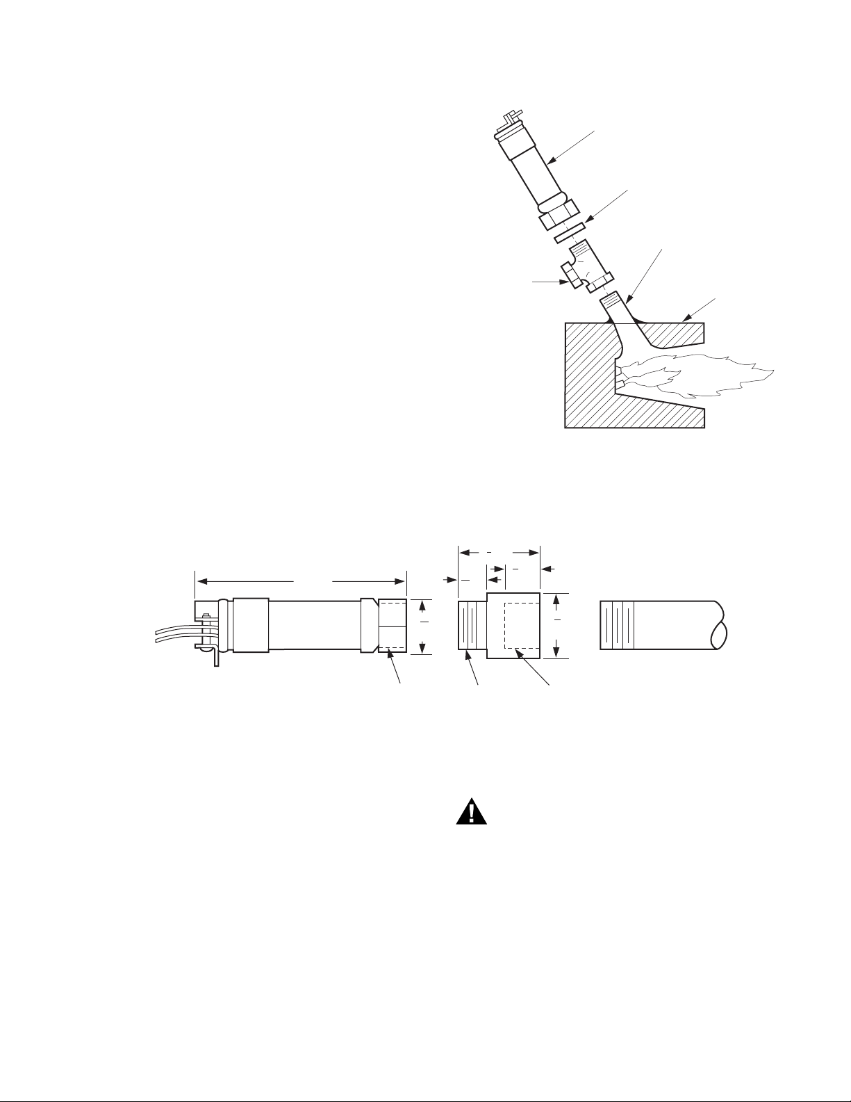
Mounting The Sight Pipe (Fig. 5)
Thread one end of the pipe to fit the mounting collar on the
detector. Cut the pipe to the desired length (as short as
practicable), and at an angle so it fits flush with the wall of the
combustion chamber. Tack-weld the pipe to the wall in a trial
position. Do not permanently weld the sight pipe in place until
after completing the Adjustments and Checkout beginning on
page 9.
NOTE: If you use a swivel mount (part no. 118367A) and you
are positive about the location and sighting angle, you
can permanently weld the pipe.
TEMPORARY
TACK WELD
FLARED HOLE
BLACK IRON
SIGHT PIPE
REFRACTORY
M3019A
BOILER
PLATE
Fig. 5. Mounting sight pipe.
If a C7027A or C7927A is to be used for a blast tube
installation, its location should be determined by the burner
manufacturer; contact the manufacturer before making any
modifications to the installation.
In locations where water is usually sprayed on the body of the
detector, use a C7035A. Internal threads in its base permit the
use of waterproof flexible conduit for this type of application.
Prepare Hole In Wall Of Combustion Chamber
Cut a hole of the proper diameter for the sight pipe in the wall
of the combustion chamber at the selected location. Flare the
hole to leave room for small adjustments of the sighting angle.
The taper of the hole should be about 1 in. for every 3 in.
(25 mm for every 76 mm) of wall thickness.
Sight Pipe Ventilation
It may be necessary to ventilate the sight pipe to cool the flame
detector or to clear the sight pipe of UV radiation absorbing
substances such as smoke, excessive moisture or, in some
instances, unburned fuel.
For a negative pressure combustion chamber, drilling a few
holes in the section of the sight pipe outside of the combustion
chamber will allow air at atmospheric pressure to flow through
the sight pipe into the chamber. A perforated pipe nipple
between the sight pipe and the detector can also be used
(see Fig. 6).
For a positive pressure combustion chamber, connect a supply
of pressurized air from the burner blower through the sight pipe
into the chamber. The supply air pressure must be greater than
the chamber pressure.
60-2026—13 6
Page 7
C7027A, C7035A, C7044A, C7927A MINIPEEPER® ULTRAVIOLET FLAME DETECTORS
Swivel Mount
To facilitate proper sighting of the flame, a swivel mount
(part no. 118367A) is available. The swivel mount will require a
3/4 to 1/2 in. reducer and a 1/2 in. close nipple to mount a
C7027A or C7927, or a 1 in. pipe at least 2-1/2 in. (63.5 mm)
long to mount a C7035A. For mounting details, refer to form
60-0361 for the 118367A Swivel Mount.
Mount The Detector (Fig. 6)
Mount the detector onto the sight pipe, pipe tee, nipple, or
other fitting. Make sure the flange gasket is in place inside the
mounting collar on the detector, and then screw the collar onto
the sight pipe or fitting.
NOTE: If a window is installed between the UV detector and
the flame, it must be fabricated from quartz or fused
silica. Ordinary glass filters out ultraviolet radiation.
Using a Heat Block With a C7027 or C7927 (Fig. 7)
If the temperature of the sight pipe will become high enough to
cause the C7027A or C7927 to overheat (above 215°F (102°C)
up to 266°F (130°C), screw a 136733 Heat Block (order
separately) onto the sight pipe before mounting the detector.
C7027A, C7927 (OR C7035A)
FLANGE
GASKET
ADD PIPE TEE,
PERFORATED
NIPPLE, OR OTHER
SUITABLE DEVICE
FOR VENTILATION,
IF REQUIRED.
BLACK IRON
SIGHT PIPE
Fig. 6. Mounting a C7027A or C7927A on a
combustion chamber (viewed from above).
C7035A mounting is similar.
COMBUSTION
CHAMBER
WALL
M24735
C7027A DETECTOR
4 [102]
1
[27]
1/2-14 NPSM
INTERNAL
THREADS
HIGH TEMPERATURES (ABOVE 215 F [102 C])
DO NOT USE FOR TEMPERATURES ABOVE 266 F [130 C]
Fig. 7. Mounting dimensions of 136733 Heat Block in in. (mm).
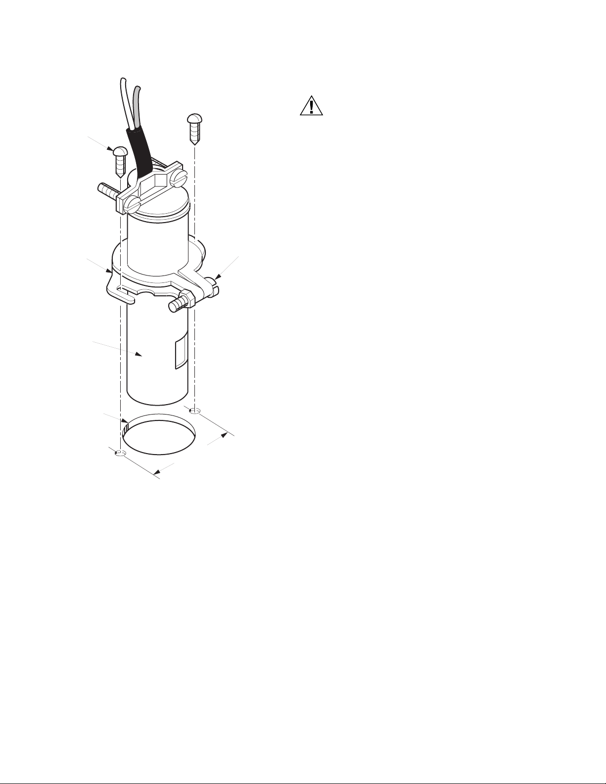
Mounting a C7044A On a Blast Tube (Fig. 8)
The C7044 is designed to be mounted on the blast tube of a
burner. The exact location should be determined by the burner
manufacturer. Contact the manufacturer before making any
modifications to the installation.
136733 HEAT BLOCK
9
[14]
16
1
16
5
1 [41]
8
5
[16]
8
1/2-14 NPSM
EXTERNAL
THREADS
1
[32]
1/2-14 NPSM
INTERNAL
THREADS
1/2-INCH SIGHT PIPE
1
4
M1942
WARNING
Explosion Hazard.
Can cause serious injury or property damage.
The C7044 will allow air leakage through its housing.
Do not locate the C7044 in an atmosphere of fuel
vapors under positive pressure. The C7027, C7035 or
C7927 should be used if internal pressure seal-off is
required.
7 60-2026—13
Page 8
C7027A, C7035A, C7044A, C7927A MINIPEEPER® ULTRAVIOLET FLAME DETECTORS
WIRING (ALL MODELS—FIG. 9)
8-32 RHIS
(EUROPEAN M-4)
SCREW (2)
MOUNTING
BRACKET
C7044A
DETECTOR
29/32 IN. (23.0 mm)
MOUNTING HOLE
IN BLAST TUBE
CLAMP
SCREW
CAUTION
Equipment Damage Hazard.
Can cause improper operation.
The blue (tan with blue tracer with C7035A1080)
leadwire must be connected to the F terminal of the
flame safeguard control subbase or terminal strip and
the white (tan leadwire without blue tracer with
C7035A1080) to the G terminal (see Fig. 9). Failure to
observe the circuit polarity by reversing the leadwires
(even momentarily) may cause the flame detector to
improperly supervise the combustion flame.
IMPORTANT
All wiring must comply with applicable local electrical
codes, ordinances and regulations. Use NEC Class 1
wiring.
The detector has color-coded and labeled, plastic-insulated,
no. 18 AWG leadwires, eight ft. (2.44 m) long, rated for 221°F
(105°C).
1. Keep the flame signal leadwires as short as possible
from the flame detector to the terminal strip or wiring
subbase. Capacitance increases with wire length, reducing the signal strength.
NOTE: The maximum permissible leadwire length depends
on the type of leadwire and the conduit type and
diameter. The ultimate limiting factor in flame signal
leadwire length is the signal current or voltage at the
flame safeguard device. See Table 1.
1-27/64 IN.
(36.1 mm)
M3020
Fig. 8. Mounting C7044A Detector on blast tube.
The C7044 is mounted in a 29/32 in. (23.0 mm) hole in the
blast tube. The mounting bracket is fastened to the blast tube
with 2 screws on 1-27/64 in. (36.1 mm) centers.
The mounting bracket is designed so that the detector can be
removed from the blast tube for cleaning and then replaced
without disturbing the sighting angle. Loosen the 2 screws
holding the bracket to the blast tube, but do not loosen the
clamp screw on the bracket. Twist both the bracket and
detector to remove them.
2. If needed, splice detector leadwires for longer leadwire
runs, observing the following considerations:
a. Make required splices in a junction box.
b. Use moisture-resistant no. 14 wire suitable for at
least 167°F (75°C).
c. For high temperature installations, use Honeywell
Specification no. 32004766-003 or equivalent for the
F leadwire. This wire is rated up to 400°F (250°C) for
continuous duty. It is tested for operation up to 20 Kv
and for breakdown up to 35 Kv. For the other
leadwires, use moisture-resistant no. 14 wire
selected for a temperature rating above the
maximum operating temperature.
d. F and G wires must be run in their own conduit
independent of other power carrying leadwires. More
than one scanner F and G wire can be run in the
same conduit.
e. A shielded twisted pair wire may be substituted for
using conduit for routing the F leadwire. Be advised
of the capacitance per foot of shielded wire
effectively reduces the flame signal at the flame
safeguard device. Be sure to ground the shield to the
G terminal at the flame safeguard wiring subbase.
f. The detector wires need to be run in their own
conduit as well, avoiding other electrical noise
carrying wiring.
g. The scanner wires should remain separated a
minimum of two in. (51 mm) from other line voltage
wires in the main control panel to the flame
safeguard device.
60-2026—13 8
Page 9

C7027A, C7035A, C7044A, C7927A MINIPEEPER® ULTRAVIOLET FLAME DETECTORS
3. Avoid installation considerations that can influence
detector operation and maximum leadwire length, such
as:
a. Moisture.
b. Ignition interference.
c. High resistance connections—poor grounds.
d. Leadwire capacitance.
e. Voltage fluctuations.
f. Induced line transients.
g. Floating grounds—ground at some voltage above
earth ground.
h. No G wire—burner used as ground.
i. Detector output less than maximum attainable for the
installation (inadequate sighting.
IMPORTANT:
Do not run the flame detector wiring in the same conduit with high voltage ignition transformer wires.
Connecting Detectors In Parallel
(C7927 Can Not be Used in Parallel)
For a flame that is difficult to sight, using two flame detectors
connected in parallel will reduce the occurrence of nuisance
shutdowns. If only one of the parallel detectors loses the flame
signal, the other will continue to indicate the presence
of the flame and keep the burner in operation.
When the flame detectors are connected in parallel, the low
level background signals are additive. Therefore, no more than
two C7027A, C7035A, or C7044A Flame Detectors should be
paralleled. Furthermore, the background signal increases as
temperature decreases. Because of this, the minimum ambient
operating temperature must be increased when the C7027A,
C7035A or C7044A Flame Detectors are paralleled. (C7927
can not be used in parallel.)
When using detectors rated for a minimum of 0°F (-18°C), limit
the minimum ambient temperature at the detectors to 32°F
(0°C). When using detectors rated for a minimum of
-40°F (-40°C), limit the minimum ambient temperature at the
detectors to -10°F (-23°C).
Connect the blue leadwires of both detectors to the F terminal
of the wiring subbase or terminal strip, and the white leadwires
of both detectors to the G terminal, as shown in Fig. 9.
Earth Ground
The detector and the flame safeguard control must be
connected to earth ground. A convenient method of
accomplishing this is to connect the detector to the flame
safeguard control with a flexible conduit, or ensure a good
ground connection at the mounting bracket.
WIRING SUBBASE
OR
TERMINAL STRIP
M3018
UV DETECTOR
UV DETECTOR
OPTIONAL
SECOND
DETECTOR
BLUE
WHITE
BLUE
WHITE
F
G
Fig. 9. Wiring C7027A, C7035A, and
C7044A flame detectors in parallel.
ADJUSTMENTS AND CHECKOUT
Before welding the C7027A, C7927A or C7035A sight pipe
in its final location, or before tightening the C7044A clamp
screw, complete both the adjustments and checkout tests that
follow and any required by the burner manufacturer.
UV Sensor Tube Test
NOTE: For initial burner lightoff, consult the burner
manufacturer instructions or the instructions
for the flame safeguard control.
During the initial burner lightoff, make sure the flame safeguard
control starts (i.e., the load relay, usually 1K, pulls in). If it does
not start, visually check the sensing tube in the C7027A,
C7035A, or C7044A flame detector. If the tube continues to
glow when no flame is present, replace the sensing tube
(C7035A), or replace the detector (C7027A or C7044A).
Adjust Detector Sighting Position
With the flame detector installed and burners running, adjust
the position of the flame detector for optimum flame signal. The
flame signal will be read in microamps or voltage (Vdc)
depending on the Honeywell flame safeguard combustion
control used.
Most existing Honeywell flame safeguard controls incorporate
a flame current jack on the flame amplifier or on the control
itself. The flame signal can be measured with a volt-ohmmeter
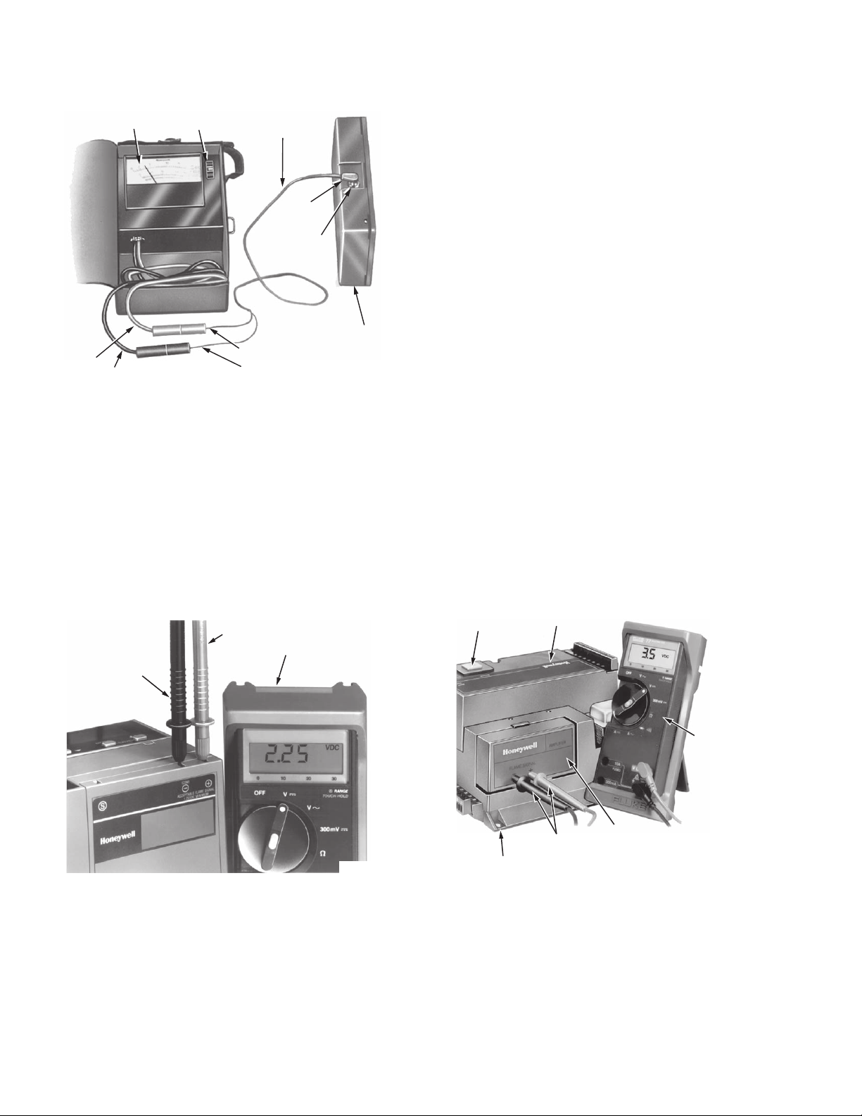
such as the Honeywell W136A. To measure the flame current
(signal), use a cable connector (part number 196146, included
with the W136A) in conjunction with the meter. With the
W136A (or equivalent) positioned at the zero to 25
microampere scale, make connections from the meter probes
to the two ends of the cable connector plug (red to red, black to
black). Make these connections before inserting the plug end
of the connector plug into the flame jack of the control
or control amplifier (see Fig. 10). Read the flame signal in
microamperes directly from the W136A meter. Refer to
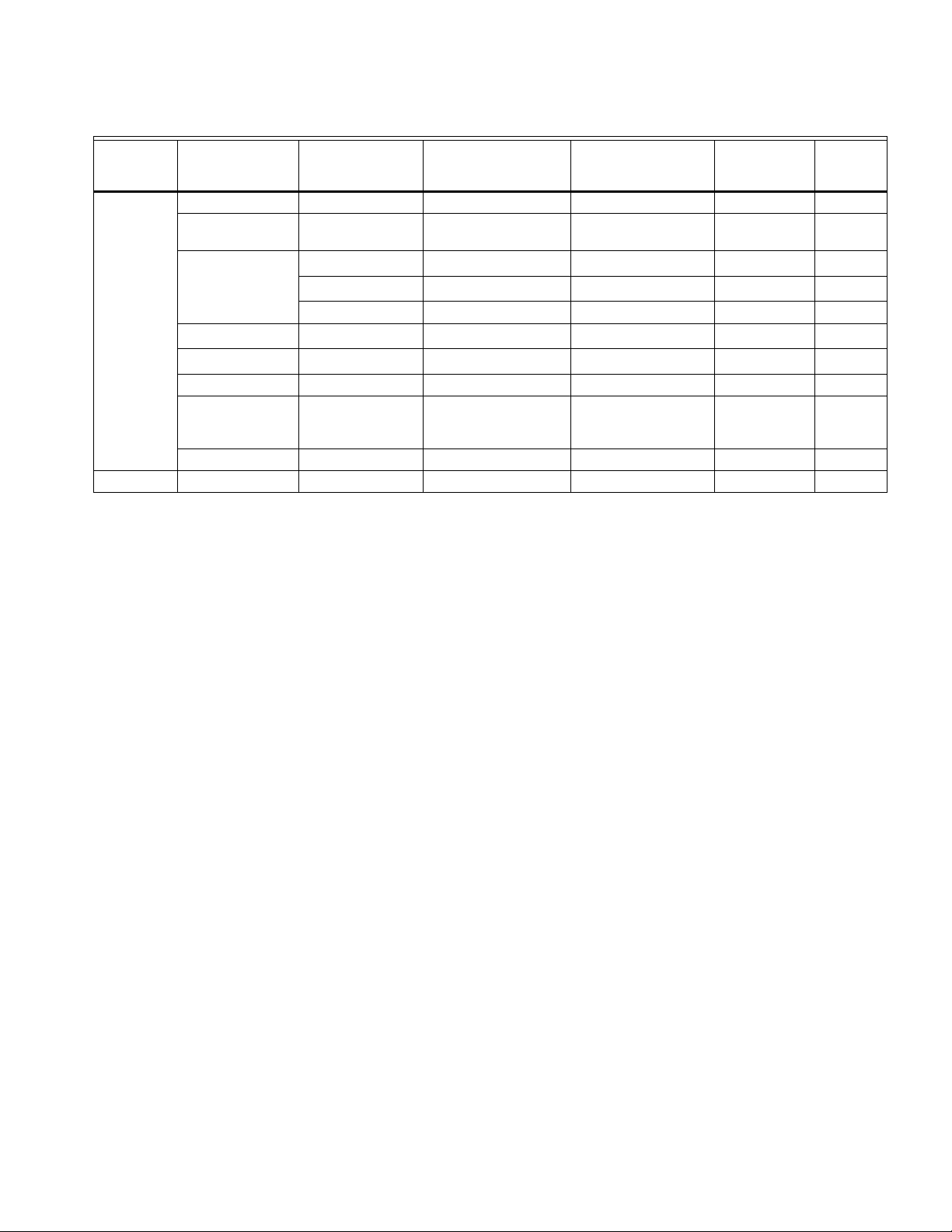
Table 1 for the minimum acceptable flame currents.
9 60-2026—13
Page 10
C7027A, C7035A, C7044A, C7927A MINIPEEPER® ULTRAVIOLET FLAME DETECTORS
Measure the flame signal voltage as illustrated in Fig. 11 and
W136A VOLTOHMMETER
W136A SELECTOR
SWITCH
196146 METER
CONNECTOR
PLUG
12. Be careful to connect the positive meter lead to the positive
(+) amplifier jack and the negative meter lead to the negative
(-) amplifier jack (BCS 7700) or the (-Com) jack for a 7800
SERIES control. If the BCS 7700 and Series 7800 controls
have the optional Keyboard Display Module, a zero to five Vdc
reading will be displayed on the module.
PLUG
FLAME SIGNAL
METER JACK
Move the flame detector and sight pipe (if not permanently
attached to the burner/boiler) to view the flame from various
positions. Allow a few seconds for the meter reading to
stabilize. A maximum steady microamp or voltage reading is
desirable. The flame signal must be above the minimum
acceptable level for the flame safeguard control and
associated amplifier as indicated in Table 1.
RED (+)
METER
LEAD
PLUG-IN FLAME
SIGNAL AMPLIFIER
RED CONNECTOR
BLACK CONNECTORBLACK (-) METER LEAD
M6532A
Measure the flame signal for the pilot alone, the main burner
flame alone, and both together (unless monitoring pilot only
when using an intermittent pilot or supervising the main flame
only when using direct spark ignition). Also, measure the flame
signal at low and high firing rates and while modulating (if
Fig. 10. Measuring microamp flame signal.
applicable).
The R7749B and R7849A,B Amplifiers used with the
Honeywell BCS 7700 and 7800 SERIES controls, respectively,
have a dc voltage flame signal output.
For the R7749B Amplifier, a volt-ohmmeter with a zero to 5 or
10 Vdc scale and a minimum sensitivity of 20,000 volts/ohm is
suggested.
For the R7849A,B or R7851B Amplifiers used with the 7800
SERIES controls, a volt-ohmmeter with a zero to 5 or 10 Vdc
scale and a minimum sensitivity of one megohm/volt is
recommended, (see Fig. 11).
POSITIVE (+)
NEGATIVE (-)
METER LEAD
METER LEAD
ONE
MEGOHM/VOLT
METER
M7382
Fig. 11. Measuring flame signal voltage
of 7800 SERIES controls.
With the flame detector in its final position, all flame signals
must be steady with a current/voltage value as indicated in
Table 1. If the minimum signal cannot be obtained or is
unstable, refer to Troubleshooting, page 12.
Pilot Turndown Test
If the detector is used to prove a pilot flame before the main
fuel valve can be opened, perform a Pilot Turndown Test.
Follow the procedures in both the Instructions for the
appropriate flame safeguard control, and in the burner
manufacturer's instructions.
RESET
BUTTO N
BCS 7700 CHASSIS MODULE FOOTMOUNT
Fig. 12. Measuring the BCS 7700 flame signal voltage.
PRO G RA M
MODULE
METER
PRO BES
FLAM E
AM PLIFER
20,000
VO LTOHMM
M7860
60-2026—13 10
Page 11
C7027A, C7035A, C7044A, C7927A MINIPEEPER® ULTRAVIOLET FLAME DETECTORS
Table 1. Flame Signal.
Honeywell Flame
Flame
Detector
C7027A,
C7035A,
C7044A
C7927A R7851B 7800 SERIES — — 1.25 5.0
a
Currently obsolete.
Plug-in
Amplifier
R7249A BC7000 + PM720 3.5 7.5 — —
R7749B
(AMPLICHECK™)
R7249A
R7290A
None
NONE R7795A,C,E,G 1.5 2.25 — —
R7849A or
R7849B
(AMPLICHECK™)
None RA890G 1.5 2.25 — —
Safeguard
Control
BCS7700A — — 2.2 4.98
R4075C
R4138C
R4140G,L,M 3.5 7.5 — —
R4795A,D
R7023C
7800 SERIES — — 1.25 5.0
a,Da,Ea
a,Da
a
a
Minimum Acceptable
Steady Current
(microamps)
3.5 7.5 — —
3.5 7.5 — —
1.5 2.25 — —
1.5 2.25 — —
Maximum Current
Expected
(microamps)
Minimum
Acceptable
Voltage (Vdc)
Maximum
Vol tag e
(Vdc)
Ignition Spark Response Test
Test to be sure that ignition spark is not actuating the flame
relay (usually 2K) or flame LED in the flame safeguard control.
1. Close the pilot and main burner manual fuel shutoff
valves.
2. Connect the appropriate meter to the flame safeguard
control amplifier. Start the burner and run through
the ignition period. Ignition spark should occur, but
the flame relay must not pull in or the flame LED
should not light. The flame signal should not be more
than 0.25 microamp or 1.25 Vdc with the BC7700 or
7800 SERIES.
3. If the flame relay does pull in or the flame LED lights,
reposition the flame detector to increase the distance
between the flame detector and the ignition spark. If the
flame detector is not in the line of sight of the ignition
spark but appears to respond to the spark, it may be
responding to reflected spark generated UV radiation. If
so, relocate the flame detector so it does not receive the
reflected UV radiation. It may be necessary to construct
a barrier to block the UV radiation generated by the
spark from the flame detector view.
4. Continue making the adjustments until the flame signal
due to ignition spark is less than 0.25 microamp or
1.25 Vdc.
5. The use of the Q624 or Q652 solid-state ignition
transformer may also provide a method to eliminate the
C7027A, C7035A, or C7044A flame detector response
to UV radiation generated by ignition spark. The Q624
and Q652 prevents flame detector response to ignition
spark by providing alternating periods of spark
generation and UV sensor activation. If ignition spark is
detected, try reversing the leads on the Q624 or Q652.
Response to Other Ultraviolet Sources
Some sources of artificial light produce small amounts of
ultraviolet radiation. Under certain conditions, an ultraviolet
detector will respond to them as if it is sensing a flame.
Do not use an artificial light source to check the response
of an ultraviolet detector. To check for proper flame detector
operation, test for flame failure response under all operating
conditions.
Weld The Sight Pipe (or Tighten the C7044A Clamp Screw)
When the flame signal is acceptable after all adjustments are
made, remove the flame detector and weld the sight pipe in its
final position. If you are using a swivel mount, the pipe may
already be welded. Then reinstall the flame detector.
NOTE: If using a C7044A Detector with no sight pipe,
do not remove the detector; tighten the clamp
screw securely.
Final Checkout
Before putting the burner into service, check out the installation
using the procedures in the Checkout section of the
Instructions for the appropriate flame safeguard control. After
completing the checkout, run the burner through at least one
complete cycle to verify correct operation.
11 60-2026—13
Page 12

C7027A, C7035A, C7044A, C7927A MINIPEEPER
®
ULTRAVIOLET FLAME DETECTORS
TROUBLESHOOTING
WARNING
Electrical Shock Hazard.
Can cause serious injury or death.
Be extremely careful while troubleshooting the
detector; line voltage is present on some of the
terminals when power is on.
Open the master switch to disconnect power before
removing or installing the detector.
Inadequate Flame Signal
If a satisfactory flame signal cannot be obtained while
adjusting the sighting position of the detector, perform the
procedures indicated in steps 1 through 7. If other difficulties
are encountered in the system, refer to Troubleshooting in the
Instructions for the appropriate Honeywell flame safeguard
control.
1. Check for proper line voltage. Make sure the master
switch is closed, connections are correct, and power
supply is the correct voltage and frequency.
2. Check the detector wiring for defects, including:
a. incorrect connections.
b. wiring type or size of wire.
c. deteriorated wire.
d. open circuits.
e. short circuits.
f. leakage paths caused by moisture, soot, or dirt.
3. With the burner running, check the temperature at the
detector. When it exceeds 215°F (102°C) for a C7027,
C7927 or C7044, or 250°F (121°C) for a C7035:
a. use a heat block (part no. 136733) if using a
C7027A Flame Detector.
b. add the additional insulation between the wall of the
combustion chamber and the detector.
c. add a shield or screen to reflect radiated heat away
from the detector, or
d. add cooling (refer to Sight Pipe Ventilation, page 6).
4. Remove the detector and clean the viewing window with
a soft, clean cloth.
5. Clean the inside of the sight pipe (if one is used) before
reinstalling the detector.
6. If the flame signal continues to be too low, replace the
plug-in amplifier (if the control has one).
7. If you still cannot obtain a proper flame signal, replace
flame detector (C7027A, C7927, C7044A) or UV
radiation sensing tube (C7035A).
IMPORTANT:
At the completion of troubleshooting, be sure to
perform the Adjustments and Checkout beginning
on page 9.
MAINTENANCE
Periodic Maintenance
1. Clean the viewing window and sight pipe (if used) when
necessary. Remove the detector and use a soft, clean
cloth to remove accumulated contaminants from the
UV radiation sensor tube glass envelope.
2. Ultraviolet sensing tubes have a life expectancy of
40,000 hours of continuous use within the ambient
temperature and voltage ratings. Replace the sensing
tube in the C7035, or replace the C7027, C7927 or
C7044 Detector, at appropriate intervals.
3. Keep the flame detection system adjusted for the
smoothest, most reliable operation as recommended by
the burner manufacturer.
Cleaning the C7044A Detector
When necessary, clean the C7044 Flame Detector by using
the following procedure:
1. Loosen the two screws holding the C7044 mounting
bracket to the blast tube. To remove, twist the bracket
and detector. Do not loosen the clamp screw that holds
the mounting bracket to the detector.
2. Clean the viewing window with a soft, clean cloth.
3. Insert the detector into the mounting hole, and to realign
it, twist against the mounting screws. Tighten the two
mounting screws.
Automation and Control Solutions
Honeywell International Inc. Honeywell Limited-Honeywell Limitée
1985 Douglas Drive North 35 Dynamic Drive
Golden Valley, MN 55422 Toronto, Ontario M1V 4Z9
customer.honeywell.com
® U.S. Registered Trademark
© 2007 Honeywell International Inc.
60-2026—13 M.S. Rev. 04-07
 Loading...