

Page 1
63-2590-05
Series 2000
C7021F
C7023F
C7031G
C7041F
C7021P
C7023P
C7041P
C7021R
C7023R
C7041R
C7021K
C7023K
C7041K
C7021D
C7023D
C7031D
C7041D
C7021J
C7023J
C7031J
C7041J
C7021B/C
C7023B/C
C7031B
C7041B/C
C7021N
C7023N
C7041N
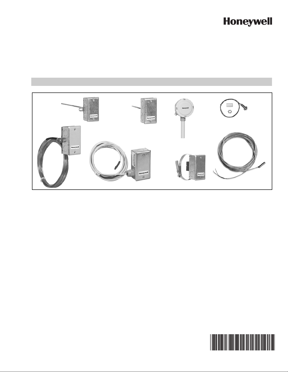
Electronic Temperature Sensors
PRODUCT DATA
APPLICATION
The Series 2000 C7021, C7023, C7031 and C7041 Electronic
Temperature Sensors are designed for use with electronic
controllers in domestic or commercial heating and cooling
systems.
FEATURES
• C7021D, C7023D, C7031D, C7041D for immersion
mounting sense water temperature.
• C7021F, C7023F, C7031G, C7041F sense outdoor air
temperature and are weatherproof for outdoor use
(knockouts allow for 1/2 in. conduit connection).
• C7021J/R, C7023J/R, C7031J, C7041J/R sense average
duct air temperature.
• C7021B/C, C7023B/C, C7031B, C7041B/C sense duct
air temperature.
• C7021K, C7023K, C7041K with strap-on mounting
senses water temperature.
• C7021N, C7023N, C7041N probe senses water or air
temperature.
• C7021P, C7023P, C7041P senses air temperature.
• Solid state components not affected by dust or dirt.
Application......................................................................... 1
Features ............................................................................ 1
Specifications .................................................................... 2
Installation ......................................................................... 8
Wiring ................................................................................11
Operation and Checkout ...................................................11
Contents
Page 2

SERIES 2000 ELECTRONIC TEMPERATURE SENSORS
SPECIFICATIONS
See Table 1 for additional specifications.
Compatability:
Use Series 2000 C7031, C7041 Temperature Sensors with
Excel 10, 15, 80, 100, and 500 controllers.
Series 2000 C7031B,D,G,J sensors are compatible with
various Honeywell controllers. The C7031G2014 is
compatible with the T7350 Commercial Thermostat.
Series 2000 C7021 temperature sensors are compatible with
TB7600, TB7300 and TB7200 communicating thermostats.
Series 2000 C7023 temperature sensors are compatible with
WEBs-AX I/O modules.
Table 1. Sensor Selection and Application Guide
Element
Model Control Application
C7021B Duct discharge air 6 in. (152) or 12
C7021C Duct discharge air 18 in. (457 mm)
C7021D
C7021F Outdoor air — -40° to 158°F
C7021J Duct discharge air
C7021K Hot water (strap-on
C7021N Water / Air (bullet
C7021P Space air
C7021R Duct discharge air
C7023B Duct discharge air 6 in. (152) or 12
C7023C Duct discharge air 18 in. (457 mm)
C7023D
Hot or chilled water
(averaging sensor
with 4 elements)
mounting)
probe)
temperature (button
probe)
(rigid copper
averaging sensor)
Hot or chilled water
f
Insertion Length
b
5 in. (127 mm)
12 ft (3.7m)
12 ft (3.7m) or 24
ft (7.3m)
in. (305 mm)
b
5 in. (127 mm)
Element
Operating Range
(-40° to 70°C)
-40° to 250°F
(-40° to 121°C)
-40° to 250°F
(-40° to 121°C)
Dimensions:
See Fig. 1 through Fig. 11.
Sensor Accuracy:
±0.36°F at 77°F (±0.2°C at 25°C) for 20K ohm NTC sensors
and 10K ohm NTC Type II and Type III sensors.
Accessories:
32006523-001 20K Probe: to allow replacement of old style
C7031D1062-1 with non-threaded well.
50001774-001 Stainless Steel 304 Well Assembly: 1/2 in.
external and internal NPT threading. Use with C7021D/
C7023D/C7031D/C7041D.
50001775-001 Well Adapter: Used with C7021D/C70231D/
C7031D/C7041D to allow threading sensor into previouslyinstalled Series 1000 32005960-001 Well.
Element Max
Ambient
Tempe rature
250°F (121°C) 10K Ohms NTC @
250°F (121°C)
Sensor Resistance
in Ohms Sensitivity
77° F Type II
10K Ohms NTC @
77° F Type III
—
—
a
ORDERING INFORMATION
When purchasing replacement and modernization products from your TRADELINE® wholesaler or distributor, refer to the
TRADELINE® Catalog or price sheets for complete ordering number.
If you have additional questions, need further information, or would like to comment on our products or services, please write or
phone:
1. Your local Honeywell Automation and Control Products Sales Office (check white pages of your phone directory).
2. Honeywell Customer Care
1885 Douglas Drive North
Minneapolis, Minnesota 55422-4386
3. http://customer.honeywell.com or http://customer.honeywell.ca
International Sales and Service Offices in all principal cities of the world. Manufacturing in Belgium, Canada, China, Czech
Republic, Germany, Hungary, Italy, Mexico, Netherlands, United Kingdom, and United States.
63-2590—05 2
Page 3

Table 1. Sensor Selection and Application Guide
Model Control Application
C7023F Outdoor air
C7023J Duct discharge air
(averaging sensor
with 4 elements)
Element
Insertion Length
12 ft (3.7m)
Element
Operating Range
-40° to 158°F
(-40° to 70°C)
-40° to 250°F
(-40° to 121°C)
C7023K Hot water (strap-on
mounting)
f
C7023N Water / Air (bullet
probe)
C7023P Space air
temperature (button
probe)
C7023R Duct discharge air
(rigid copper
averaging sensor)
12 ft (3.7m) or 24
ft (7.3m)
-40° to 250°F
(-40° to 121°C)
C7031B Duct discharge air 6 in. (152 mm) -40° to 250°F
(-40° to 121°C)
C7031D Hot or chilled water 5 in. (127 mm) 40° to 350°F
(4° to 115°C)
C7031G
-2006
C7031G
-2014
C7031J Duct discharge air
Outdoor air — -40° to 120°F
(-40° to 49°C)
Outdoor air —
d
-40° to 120°F
(-40° to 49°C)
12 ft (3.7m) 40° to 180°F
(averaging sensor
(4° to 82°C)
with 4 elements)
C7041B Duct discharge air 6 in. (152 mm) or
12 in. (305 mm)
-40° to 250°F
(-40° to 121°C)
C7041C Duct discharge air 18 in. (457 mm)
b
C7041D
Hot or chilled water
5 in. (127 mm)
C7041F Outdoor air — -40° to 158°F
(-40° to 70°C)
C7041J Duct discharge air
12 ft (3.7m)
(averaging sensor
with 4 elements)
SERIES 2000 ELECTRONIC TEMPERATURE SENSORS
Element Max
Ambient
Tempe rature
250°F (121°C)
250°F (121°C)
370°F (187°C)
120°F (49°C)
120°F (49°C)
250°F (121°C)
250°F (121°C)
Sensor Resistance
in Ohms Sensitivity
10K Ohms NTC @
77° F Type III
1097 at 77° (25°C)
1097 at 77° (25°C)
c
c
1715 at 90°F (32°C)
3484 at 77°F (25°C)
1097 at 77° (25°C)
c
20K Ohms NTC at
77°F (25°C)
e
2.1 (3.9)
2.1 (3.9)
c
2.2 (3.4)
c
2.1 (3.9)
2.1 (3.9)
—
a
—
C7041K Hot water (strap-on
f
C7041N
mounting)
Water / Air (bullet
probe)
C7041P Space air
temperature (button
probe)
C7041R Duct discharge air
(rigid copper
averaging sensor)
-40° to 250°F
(-40° to 121°C)
—
—
12 ft (3.7m) or
24 ft (7.3m)
3 63-2590—05
Page 4

SERIES 2000 ELECTRONIC TEMPERATURE SENSORS
a
Control sensitivity in ohms per degree F (per degree C) for element operating range.
b
Order immersion well separately (50001774-001)
c
Resistance increases as temperature increases.
d
Use with T7350 Commercial Thermostat.
e
Nonlinear resistance decreases as temperature increases.
f
Not equipped with well; temperature sensed at surface of pipe.
63-2590—05 4
Page 5
SERIES 2000 ELECTRONIC TEMPERATURE SENSORS
2-5/16
(59)
15/16
(23)
1-11/16
(43)
4-3/16
(107)
3/4
(19)
4
(102)
1-11/16
(43)
C7031B: 5-11/16 (145)
C7021B, C7023B, C7041B: 11-5/8 (295)
C7021B, C7023B, C7041C: 17-5/8 (448)
M27010A
1-13/16
(46)
7/16 (12)
1/8 NPSM (3)
3-7/8 (99)
1 (26)
11/16
(18)
5/8 (16)
M22821
5/16
(8)
SPACER SENSOR
1 (26)
7/8 (22)
3/16 (4)
3/8 IN.-16 THREAD
Sensor Resistance
Table 2. Typical Resistance of Sensor Models.
Typical Resistance (in ohms)
C7021 Sensors
(10K Ohm NTC Type II)
At 41°F (5°C) 25,392 23,467 1,020 54,200
At 50°F (10°C) 19,901 18,789 1,039 41,758
At 59°F (15°C) 15,712 15,137 1,059 32,427
At 68°F (20°C) 12,493 12,268 1,078 25,370
At 77°F (25°C) 10,000 10,000 1,097 20,000
At 86°F (30°C) 8,057 8,196 1,117 15,856
At 95°F (35°C) 6,531 6,754 1,136 12,654
C7023 Sensors
(10K Ohm NTC Type III)
C7031 Sensors
(1097 Ohms PTC)
C7041 Sensors
(20K ohm NTC)
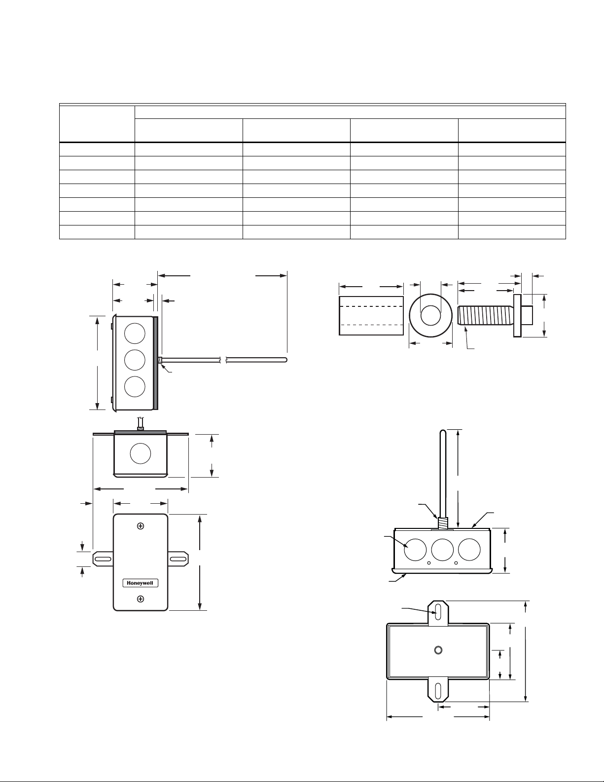
Fig. 1. C7021B/C, C7023B/C, C7041B/C dimensions in in.
(mm).
Fig. 2. Dimensions of the C7021P, C7023P, C7041P in in.
(mm)
5.75 ± 0.25
(146)
1/8 INCH NPSM
STRAIGHT
THREADS
[8] 1/2 INCH
CONDUIT
KNOCKOUTS
SINGLE GANG
RACO COVER
[2] 1/64 (5) X 5/8 (16)
MOUNTING HOLES
2-3/32 (53)
4-3/16 (106)
FOAM PAD
1-59/64
(49)
2-19/64
(58)
1-5/32
(29)
3-57/64
(99)
M27006
Fig. 3. C7031B dimensions in in. (mm)
5 63-2590—05
Page 6

SERIES 2000 ELECTRONIC TEMPERATURE SENSORS
2-1/4 (57)
3/4
(19)
1 (25)
5
(127)
7/8
(22)
8-5/16
(211)
M22132
3-5/8 (91)
2-5/16
(59)
1-11/16
(43)
4-3/16
(107)
1/4
(6)
4
(70)
1-11/16
(43)
6-11/16 (170)
M22596
5 (127)
1/2 NPSM (13)
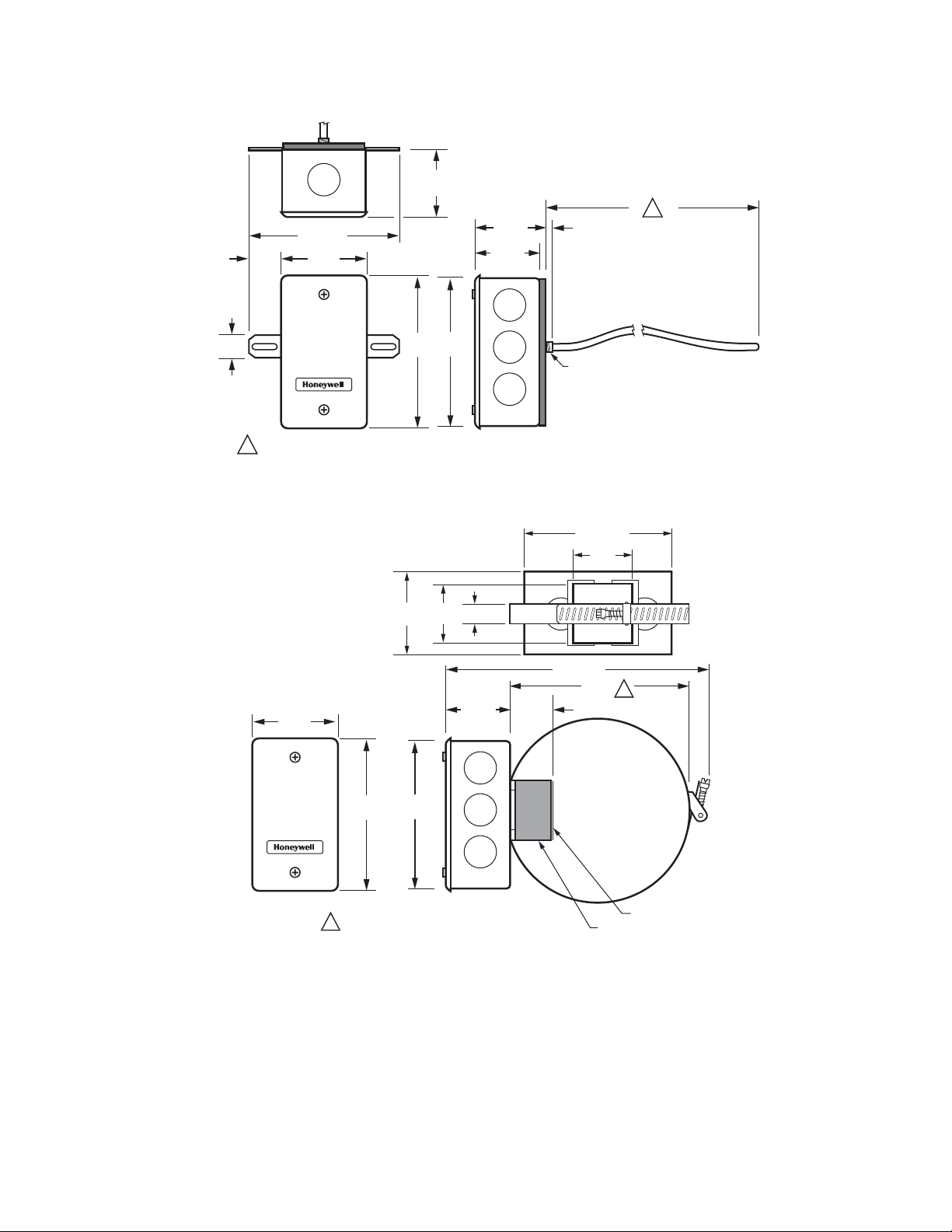
Fig. 4. C7031G, C7021F, C7023F, C7041F dimensions in in.
(mm).
Fig. 5. C7021D, C7023D, C7031D, C7041D dimensions in in. (mm)
NOTE: The C7021D, C7023D, C7041D uses the 50001774-
001 Well Assembly. See Fig. 4 for dimensions.
FITS 1/2 NPT TAPPED HOLE
(26)
3/4
1
(19)
(mm)
1/2 NPSM
INTERNALLY
THREADED
Fig. 6. 50001774-001 Immersion Well dimensions in in.
4 (102)
3/8 (10)
M27052
63-2590—05 6
Page 7
SERIES 2000 ELECTRONIC TEMPERATURE SENSORS
2-5/16
(59)
15/16
(23)
1-11/16
(43)
4-3/16
(107)
3/4
(19)
4
(70)
1-11/16
(43)
M22818
1-13/16
(46)
7/16 (12)
1/8 NPSM (3)
3-7/8 (99)
DEPENDING ON THE MODEL, THE ELEMENT LENGTH IS EITHER 12 FT (366 CM) OR 24 FT (732 CM).
1
1
2-5/16
(59)
4-3/16
(107)
4
(70)
1-11/16
(43)
7-1/8 (182)
9/16 (14)
1-1/2
(38)
1-1/2
(38)
2-5/16
(59)
M22134
1-1/4
(32)
5 (127)
MAXIMUM PIPE DIAMETER SHOWN.
MINIMUM PIPE DIAMETER: 1-5/8 (41)
1
1
4-3/16 (107)
COPPER PLATE
FOAM PAD
Fig. 7. C7021R, C7023R, C7041R dimensions in in. (mm).
Fig. 8. C7021K, C7023K, C7041K dimensions in in. (mm).
7 63-2590—05
Page 8

SERIES 2000 ELECTRONIC TEMPERATURE SENSORS
CAUTION
2-5/16
(59)
1(25)
1-11/16
(43)
4-3/16
(107)
4 THERMISTORS PLACED
ON A 12 FOOT (3.7M) WIRE.
4
(70)
1-11/16
(43)
M22133
PROBE
1 X Ø 1/32 (1)
CONDUCTOR CABLE
POTTING MATERIAL LEVEL
0.063 MAX. FROM TOP OF PROBE
6 FT ± 6 IN (1829 ±152)
Fig. 9. C7021N, C7023N, C7041N dimensions in in. (mm).
Fig. 10. C7021J, C7023J, C7031J, C7041J dimensions in in.
(mm).
INSTALLATION
STRIP LENGTH
2X 1/4 (6)
2 ± 1/2 (51 ± 13)
M33019
Electrical Shock or Equipment Damage Hazard.
Can shock individuals or short equipment
circuitry.
Disconnect power supply before installation.
Mounting
The method of mounting depends on the particular application
of the temperature sensor. The following procedures include
outdoor, duct, immersion well and strap-on applications. Also
refer to the instructions for the electronic control.
Outdoor Mounting (C7031G, C7021F,
C7023F, C7041F)
The C7031G, C7021F, C7023F and C7041F sense outdoor air
temperature. Mount this control where it can sense average
outdoor air temperature. Normally, the north side of a building
provides a suitable location.
NOTE: These sensors are weatherproof for outdoor use.
Knockouts allow for 1/2 in. conduit connection.
1. Remove and set aside the wiring box cover.
2. Mount the sensor to standard 1/2 in. conduit.
NOTE: Mount sensor so that the element points down.
3. Make wiring connections using two wire nuts.
4. Reattach the wiring box cover.
When Installing this Product...
1. Read these instructions carefully. Failure to follow them
could damage the product or cause a hazardous
condition.
2. Check the ratings given in the instructions and on the
product to make sure the product is suitable for your
application.
3. Installer must be a trained, experienced service
technician.
4. After installation is complete, check out product
operation as provided in these instructions.
63-2590—05 8
Duct Mounting
The C7031B, C7031J, C7021B/C/J, C7023B/C/J, C7041B/C/J
can be mounted in a duct to sense air temperature.
IMPORTANT
Select a spot for the sensor where it will be exposed
to average duct air temperature. Avoid locations
where stratification can cause sensing errors.
C7021B,C/C7023B/C, C7041B/C MOUNTING
1. Cut a hole in the duct just large enough to accept the
sensing element.
2. Use the sensor case to mark the locations of the pilot
holes for the mounting screws.
3. Drill the pilot holes and fasten the sensor to the duct.
Page 9
SERIES 2000 ELECTRONIC TEMPERATURE SENSORS
M8929A
SENSING ELEMENTS (4)
DUCT
GROMMET
(NOT
INCLUDE)
SENSOR
SUPPORTS (2)
PLASTIC
TIES (5)
A
M22820
COPPER TUBING
WITH SENSING
ELEMENTS (4 OR 9)
DUCT
SENSOR
SUPPORTS (2)
PLASTIC
TIES (5)
NUMBER OF ELEMENTS DEPENDS
ON LENGTH OF COPPER TUBING.
1
1
M22819
DUCT
SENSOR
COPPER TUBING WITH
SENSING ELEMENTS (4 OR 9)
NUMBER OF ELEMENTS DEPENDS
ON LENGTH OF COPPER TUBING.
1
1
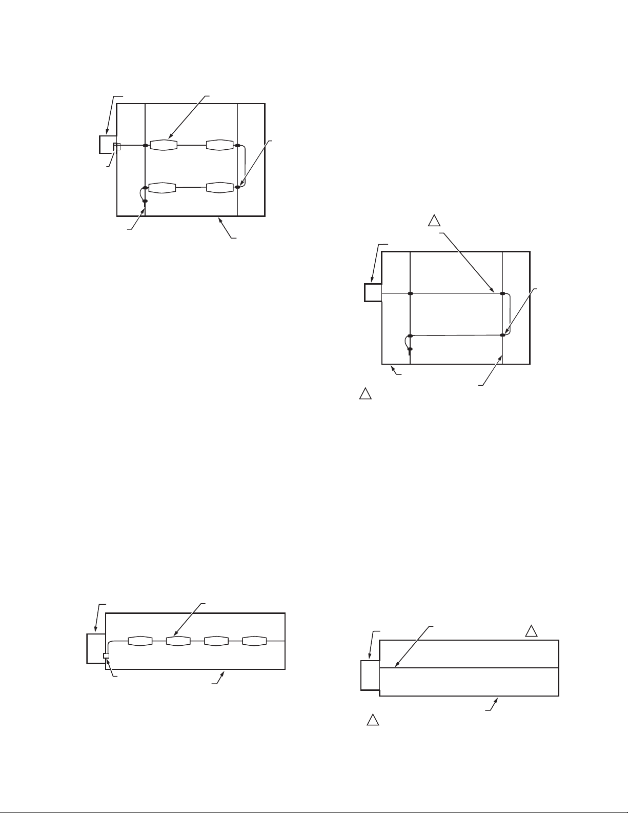
C7021J, C7023J, C7031J, C7041J MOUNTING
Fig. 11. Duct cross section showing method of installing
C7021J, C7023J, C7031J, C7041J Averaging Electronic
Sensor.
1. Install two supports inside the duct to hold the averaging
element.
2. Cut a 7/8 in. (22 mm) hole in the side of the duct to insert
the averaging element.
3. Fasten the terminal box to the outside of the duct and
thread the element through the hole and into the duct.
4. Use plastic wire ties to fasten the element to supports.
Seal the hole around the element with a rubber
grommet.
5. Secure the end of the element to the duct on the
support to prevent continuous flexing or abrasion.
C7021R, C7023R, C7041R MOUNTING
1. Install two supports inside the duct to hold the
averaging element.
2. Cut a 7/8 in. (22 mm) hole in the side of the duct.
3. Insert the averaging element into the duct through the
hole.
4. Fasten the terminal box to the outside of the duct and
thread the element through the hole and into the duct.
5. Use plastic wire ties to fasten the element to the
supports. Seal the hole around the element with a rubber
grommet.
6. Secure the end of the element to the duct on the
support to prevent continuous flexing or abrasion.
IMPORTANT
NOTE: When the sensor is used as a deck sensor in a
Install one C7021J, C7023J, C7031J, C7041J just upstream
from the cold deck zone dampers and the other C7021J,
C7023J, C7031J, C7041J upstream from the hot deck zone
dampers. Position the thermistors to sense the average deck
temperature.
Fig. 12. Duct cross section showing method of installing
C7021J, C7023J, C7031J, C7041J in a multizone system.
To assure that the C7021J, C7023J, C7031J, C7041J
senses average duct temperature, position the
temperature elements approximately as shown in Fig.
11. Do not allow the elements to touch or be close to
the duct sides.
multizone system, be sure to space the elements
equally in the duct midstream as shown in Fig. 12.
SENSOR
GROMMET
(NOT FURNISHED)
SENSING ELEMENTS (4)
DUCT
Fig. 13. Duct cross section showing method of installing
C7021R, C7023R, C7041R Averaging Electronic Sensor.
IMPORTANT
To ensure that the C7021R, C7023R, C7041R senses
average duct temperature, position the temperature
elements approximately as shown in Fig. 13. Do not
allow the elements to touch or be close to the duct
sides.
NOTE: When the sensor is used as a deck sensor in a
multizone system, be sure to space the elements
equally in the duct midstream as shown in Fig. 14.
Install one C7021R, C7023R, C7041R just upstream from the
cold deck zone dampers and the other C7021R, C7023R,
C7041R upstream from the hot deck zone dampers. Position
the thermistors to sense the average deck temperature.
M8928
Fig. 14. Duct cross section showing method of installing
C7021R, C7023R, C7041R in a multizone system.
9 63-2590—05
Page 10

SERIES 2000 ELECTRONIC TEMPERATURE SENSORS
1/2 NPT (13)
M22135
SENSING ELEMENT
(SEALED IN STAINLESS STEEL
TUBE INSIDE OF INSERTION WELL)
M22136
SENSOR
PIPE
COPPER PLATE MUST
MAKE GOOD CONTACT
WITH METAL PIPE
WORM GEAR
Immersion Well Mounting (C7021D,
C7023D, C7031D, C7041D)
The C7031D Sensor includes an immersion well. The C7021D,
C7023D, and C7041D sensors do not include a well. For the
C7021D, C7023D, and C7041D, order the well as an
accessory (part no.: 50001774-001).
When used on a boiler, follow the manufacturer instructions for
location. If a tapped hole is not provided for the immersion well,
provide one as follows:
1. Drain boiler and drill a 23/32 in. (18 mm) hole at the
selected location.
2. Cut threads in the hole with a 1/2 in. (13 mm) by 14 NPT
tap.
In other installations, mount the immersion well in an elbow
with a heel outlet as shown in Fig. 15.
1. Drain the system, if you have not already done it, and
open the tapped hole.
2. Put pipe joint compound on the threads of the
immersion well and screw it into the tapped hole or
elbow, tightening it securely.
3. Refill the system and check for leaks.
Mount the C7021D, C7023D, C7031D and C7041D into the
well:
NOTE: Mounting using previously installed Honeywell
wells (part no.: 32005960-001) requires an
adapter (part no.: 50001775-001).
makes contact before mounting (remove insulation from the
pipe at the point of installation if necessary). Thermal
compound is recommended with the strap-on C7021K,
C7023K, C7041K Sensor. Locate the sensor on the discharge
pipe within 3 feet (0.9m) of the boiler. See Fig. 16.
Fig. 16. Strap-on mounting of C7021K, C7023K, C7041K
Sensor.
NOTE: Insulation around the contact area increases sensor
accuracy.
1. When an adapter is required, first thread it into the well
no more than one or two turns.
2. Slide the sensor into the well.
3. Rotate the sensor to thread it tightly into the adapter and
the adapter tightly into the well.
Fig. 15. Method of mounting C7021D, C7023D, C7031D,
Strap-On Mounting (C7021K, C7023K,
C7041K)
Strap-on mounting is well-suited for retrofit applications where
installation costs can be reduced by not draining the system.
The C7021K, C7023K, C7041K Sensor mounts on metal pipes
from 1-5/8 inch to five inches in diameter using the straps
supplied. Clean the surface of the pipe where the sensor
C7041D Sensor.
Button Probe Mounting
The C7021P, C7023P, C7041P Button Probe Sensor design
simplifies mounting into a variety of standard structural
materials.
The locking nut can be used to secure the probe. See Fig. 18.
The plastic spacer helps insulate the probe from drywall, wood,
or other material in which the probe is mounted. The spacer is
sized to fit snugly into 1/2 in. metal conduit. See Fig. 17.
NOTES:
— The plastic spacer is threaded for easy installation.
— Use of both the locking nut and spacer requires
cutting spacer to shorter length.
C7041P MOUNTING RECOMMENDATIONS
Determine the proper location based upon the following:
— Mount the probe to an inside wall approximately 54 in.
(1372 mm) from the floor (or in the specified location) to
allow exposure to the average zone temperature.
— Do not mount the probe to an outside wall, a wall containing
waterpipes, or near air ducts.
— Avoid locations exposed to register discharge air, or
radiation from lights, appliances, or the sun.
M22797
Fig. 17. Mounting sensor in conduit.
63-2590—05 10
Page 11

Fig. 18. Mounting sensor in wall with nut only.
CAUTION
CAUTION
M22799
WALL
Bullet Probe Sensor Mounting (C7021N,
C7023N, C7041N)
The bullet probe sensor is a water-resistant sensor that
provides a cost-effective solution for surface contact
temperature measurement of conditioned water pipes, low
pressure steam or refrigerant lines. These sensors are ideal for
applications where immersion wells are not practical to install.
These sensors can also be use to sense air temperature.
SERIES 2000 ELECTRONIC TEMPERATURE SENSORS
Electrical Shock or Equipment Damage Hazard.
Can shock individuals or short equipment
circuitry.
Disconnect power supply before installation.
IMPORTANT
1. All wiring must agree with applicable codes,
ordinances and regulations.
2. Do not mount sensor in incorrect environment.
3. Wire according to the applicable controller
instructions.
OPERATION AND CHECKOUT
Operation
The C7041 Temperature Sensors are designed for use with
XL500, XL100, XL50, XL15, XL10, and Honeywell LCBS
Controllers or any controller requiring 20K ohm NTC
non-linear input. As the temperature at the C7041 Sensor
increases, the resistance of the sensor decreases, causing the
controller to operate and offset the temperature change.
The C7021 Temperature Sensors are designed for use with the
TB7600, TB7300, and TB7200 Series Communicating
Thermostats or any controller requiring a 10K ohm NTC Type II
input.
The C7023 Temperature Sensors are designed for use with
WEBs-AX I/O Modules or any controller requiring a 10K ohm
NTC Type III input.
WIRING
Erratic System Operation Hazard.
Failure to follow proper wiring practices can
introduce disruptive electrical interference (noise).
Keep wiring at least one foot away from large inductive
loads such as motors line starters, lighting ballasts,
and large power distribution panels.
Shielded cable is required in installations where these
guidelines cannot be met.
Ground shield only to grounded controller case.
Checkout
Refer to the applicable controller instructions when checking
out the complete heating and cooling systems.
To check out the sensors, move the thermostat or remote
setpoint potentiometer below the temperature of the cooling or
heating medium. Watch the motor, valve or damper for the
correct movement.
11 63-2590—05
Page 12

SERIES 2000 ELECTRONIC TEMPERATURE SENSORS
Automation and Control Solutions
Honeywell International Inc.
1985 Douglas Drive North
Golden Valley, MN 55422
customer.honeywell.com
® U.S. Registered Trademark
© 2011 Honeywell International Inc.
63-2590—05 M.S. Rev. 08-11
Printed in United States
 Loading...