

Page 1
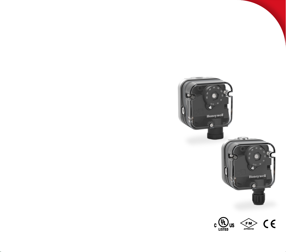
Gas pressure switch C6097
Technical Information · GB
4 Edition 01.19
• Monitoring of gas and air pressures (positive, negative and
differential pressures)
• Switches with falling or rising pressure.
• FM and UL certified:
With lock-off and hand wheel with "WC/mbar scale
• EU certified pursuant to EN 1854: Hand wheel with mbar scale
Page 2

Contents
Gas pressure switch C6097..........................1
Contents ............................................2
1 Application ........................................3
1.1 Use .................................................4
1.1.1 CE approved pressure switches .......................4
1.1.2 FM approved and UL listed pressure switches........4
1.2 Application examples ..............................5
1.2.1 Low gas pressure monitoring .........................5
1.2.2 Differential pressure monitoring . . . . . . . . . . . . . . . . . . . . . .5
1.2.3 Systems leak tightness check .........................5
1.2.4 Air line with minimum pressure and flow monitoring .6
1.2.5 Low and high gas pressure protection device.........6
2 Certification .......................................7
2.1 EU cer tified ........................................ 7
2.2 FM approved ....................................... 7
2.3 UL listed ........................................... 7
2.4 Overview of product approvals .................... 7
3 Function ...........................................8
3.1 Vent limiter .........................................8
3.2 Positive pressure measurement ...................9
3.3 Negative pressure measurement ..................9
3.4 Differential pressure measurement ...............9
3.5 Connection diagram ..............................11
3.5.1 Blue pilot lamp for 230 V AC or 110/120 V AC .......11
3.5.2 Red/green pilot LED for 24 V DC/AC or 110 –
230 V AC ....................................................11
3.6 Wiring .............................................12
4 Project planning information . . . . . . . . . . . . . . . . . . . . .13
4.1 Installation ........................................13
4.2 Ports ..............................................14
4.2.1 CE cer tified pressure switches ......................14
4.2.2 UL , FM certified pressure switches .................15
4.3 Resetting pressure switches with manual reset ..16
5 Accessories.......................................17
5.1 Fastening set with screws, U-shape bracket .....17
5.2 Connecting set ...................................17
5.3 Restrictor orifice ..................................17
5.4 Standard socket set...............................18
5.5 Standard coupler plug ............................18
5.6 Pilot lamp set, red or blue .........................18
5.7 LED set, red/green................................19
5.8 Cover for auto reset ...............................19
5.9 Cover for manual reset............................19
5.10 Weather protection cover ...................... 20
6 Technical data . . . . . . . . . . . . . . . . . . . . . . . . . . . . . . . . . . . .21
6.1 General............................................21
6.2 EU certified pressure switches ...................21
6.3 UL, FM certified pressure switches ..............22
6.4 Adjusting range, switching hysteresis ............22
6.4.1 CE certified pressure switches ......................22
6.4.2 UL, FM certified pressure switches .................23
6.5 Dimensions .......................................24
6.5.1 EU certified pressure switches...................... 24
6.5.2 UL, FM certified pressure switches .................25
6.6 Converting units ..................................26
7 Maintenance cycles...............................26
Feedback ...........................................27
For more information ...............................27
C60 97 · Edition 01.19 2
= To be continued
▼
Page 3
Application
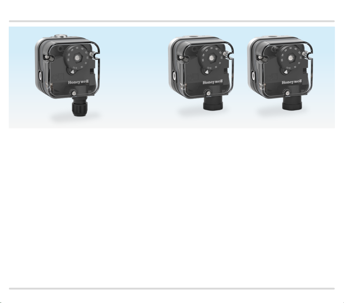
C6097 with CE approval.
Hand wheel with mbar scale.
M16 cable gland for electrical connection.
C6097 with UL listing and FM approval.
Hand wheel with "WC and mbar scale.
1/2" NPT conduit for electrical connection.
C6097 can be supplied with lock-off function.
1 Application
The pressure switch monitors extremely low pres-
sure differentials and triggers switch-on, switch-off
or switch-over operations if a set switching point is
reached.
The switching point can be adjusted using a hand
wheel.
The pressure switch monitors positive and negative gas
pressures on various industrial gas and air appliances,
such as boiler fan monitoring and differential pressure
monitoring in firing, ventilation and air-conditioning
systems.
C60 97 · Edition 01.19 3
Pressure switch C6097A switches in the event of decreasing pressure, C6097B switches in the event of
increasing pressure.
Pressure switches with manual reset lock off after
switching.
Pressure switches with an 0.2 mm (0.008") nozzle are
supplied with an integrated vent limiter, see page 8
(Vent limiter).
Page 4
Application
1.1 Use
1.1.1 CE approved pressure switches
Type Hand wheel setting/Switching properties Positive pressure Negative pressure Electrical connection
C6 097A 4110
C6 097A 4210
C6 097A 4310
C6 097A 441 0
1.1.2 FM approved and UL listed pressure switches
Type Hand wheel setting/Switching point Positive pressure Negative pressure Electrical connection
C6097A3004
C6097A3053
C6097A3079
C6097A3137
C6097A3012
C6097A3038
C6097A3095
C6097A3111
C6097B3002
C6097B3028
C6097B3051
C6097B3085
C6097B3101
C6097B3119
Hand wheel set to decreasing pressure/
C6097 switche s with rising and falling pressure
Hand wheel set to decreasing pressure/
C6097 switche s with rising and falling pressure
Hand wheel set to decreasing pressure/
C6097 switche s with falling pressure and locks of f
Hand wheel set to increasing pressure/
C6097 switche s with rising pressure and locks off
Hand wheel set to increasing pressure/
C6097 switche s with rising and falling pressure
Gas, air, flue gas or
biogas
Gas, air, flue gas or
biogas
Gas, air, flue gas or
biogas
Gas, air, flue gas or
biogas
Gas, air, flue gas or
biogas
Air, flue gas
Air, flue gas
Air, flue gas
Air, flue gas
Air, flue gas
Screw terminals and
M16 cable gland
Screw terminals
½" NPT conduit
Screw terminals and
½" NPT conduit
Screw terminals
½" NPT conduit
Screw terminals
½" NPT conduit
C60 97 · Edition 01.19 4
Page 5
Application
1.2 Application examples
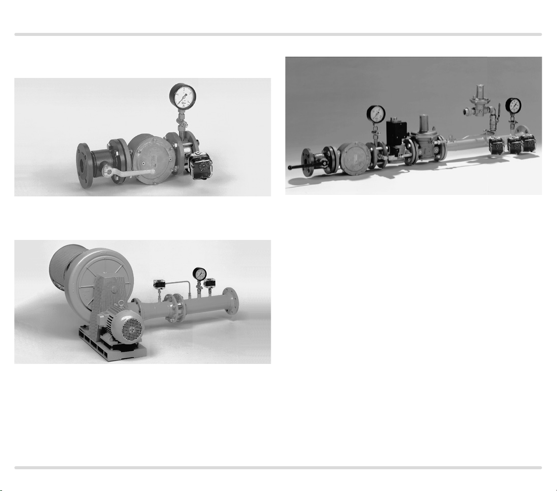
1.2.1 Low gas pressure monitoring
For monitoring the minimum gas inlet pressure
1.2.2 Differential pressure monitoring
1.2.3 Systems leak tightness check
Electronic safety shut-off valve SAV with leak tightness
check of downstream devices
Differential pressure switch for monitoring air filters
C60 97 · Edition 01.19 5
Page 6
Application
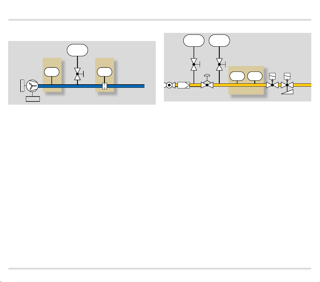
1.2.4 Air line with minimum pressure and flow
monitoring
PI
PZL PDS
C6097 C6097
1/min
KFM/RFM
The air flow generated by the fan may be monitored as
follows:
The static pressure is monitored by the pressure switch
(PZL) as long as it can be demonstrated that the display consequently shows an adequate and secured flow
of air, or the pressure switch (PDS) checks the flow of air
via the differential pressure on the orifice.
If there is no air pressure supplied or if there is no differential pressure on the orifice, the system will be blocked.
1.2.5 Low and high gas pressure protection device
AKT GFK
PI
KFM GDJ
PI
PZL PZH
KFM C6097
VAS..N VAS..L
Min./Max.
If the pressure is either too low or too high,
the min./max. pressure switch (PZL/PZH) switches in
order to avoid start-up or to initiate a safety shut-down.
C60 97 · Edition 01.19 6
Page 7
Certification
2 Certification
Certificates – see Docuthek.
2.1 EU certified
– 2014/35/EU (LVD) – Low Voltage Directive
– 2014/30/EU (EMC) – Electromagnetic Compatibility
Directive
– (EU) 2016/426 (GAR) – Gas Appliances Regulation
– EN 13611:2015+AC:2016
– EN 1854:2010
2.2 FM approved
Factory Mutual Research Class: 3510 Flow and pres-
sure safety switches. Designed for applications pursuant to NFPA 85 and NFPA 86. www.approvalguide.com
2.3 UL listed
USA and Canada
UL 353 Limit control.
Underwriters Laboratories – www.ul.com Tools (at the
bottom of the page) Online Certifications Directory
2.4 Overview of product approvals
Type EU certified FM approved UL listed
C6 097A 4110
C6 097A 4210
C6 097A 4310
C6 097A 441 0
C6097A3004
C6097A3012
C6097A3038
C6097A3053
C6097A3079
C6097A3095
C6097A3111
C6097A3137
C6097B3002
C6097B3028
C6097B3051
C6097B3085
C6097B3101
C6097B3119
–
– –
C60 97 · Edition 01.19 7
Page 8
Function
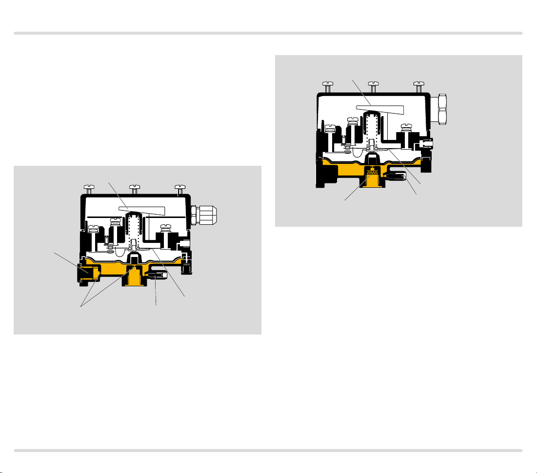
3 Function
Pressure switch C6097A switches with falling pressure,
C6097B switches with rising pressure.
Once the set switching point is reached, a micro switch
is activated in the pressure switch which is designed as
a change-over contact.
The switching pressure is adjusted using a hand wheel.
CE approved pressure switches
Hand wheel
M16 x 1.5
Screw plug,
Rp 1/4"
2
Nozzle
0.8 mm
NO
NC
COM
4
3
1
Measurement point
Micro switch
FM approved and UL listed pressure switches
Hand wheel
1/2" NPT
Conduit
NO
NC
COM
4
Micro switch
1
Filter pad/nozzle
Pressure switches which lock off after switching can
only be unlocked with a manual reset, see page 16
(Resetting pressure switches with manual reset).
Measurement point
3.1 Vent limiter
The flow on FM approved and UL listed pressure
switches is limited by the nozzle. In the event of a
diaphragm tear, the escape of gas is limited to less
than 1.0 CFH of natural gas, see max. inlet pressure,
page 23 (UL, FM certified pressure switches), Adjusting range, switching hysteresis.
C60 97 · Edition 01.19 8
Page 9
Function
▼
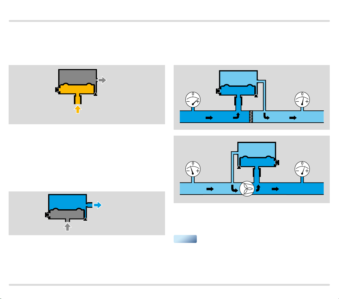
3.2 Positive pressure measurement
Positive pressure measurement is designed, for ex-
ample, for checking the fan function or measuring the
min./max. gas pressure.
4
2
1
3
Gas, air, flue gas, biogas
The positive pressure is measured in the lower dia-
phragm chamber, port 1 (or 2). The upper diaphragm
chamber is ventilated via port 4 (or 3).
3.3 Negative pressure measurement
Negative pressure measurement is designed, for exam-
ple, for monitoring a suction pressure blower.
4
2
1
Air, flue gas
3
3.4 Differential pressure measurement
Differential pressure measurement is designed for
safeguarding an air flow rate or for monitoring filters
and fans, for example.
4
2
1
4
The higher absolute pressure is connected to port 1 (or
2), and the lower absolute pressure to port 4 (or 3). The
remaining ports must be tightly plugged.
3
2
3
1
The negative pressure is measured in the upper dia-
phragm chamber, port 4 (or 3). The lower diaphragm
chamber is ventilated via port 1 (or 2).
C60 97 · Edition 01.19 9
Page 10

Function
-6 -5 -4 -3 -2 -1 0 1 2 3 4 5 6
Increasing
negative pressure
Decreasing
negative pressure
Do not connect port 4 (or 3) to pipes carrying gas! For
further information, see page 14 (Ports).
Increasing pressure
Decreasing pressure
C60 97 · Edition 01.19 10
Page 11

Function
NC
1
COM
3
NO
NO
2
N
NO
2
NC
1
COM
3
L1
N
3.5 Connection diagram
L1
3
COM
0
NO
2
NC
1
Contacts 3 and 2 close when subject to increasing
pressure.
Contacts 1 and 3 close when subject to falling pressure.
On pressure switches that switch with rising pressure:
The contact switches from NC 1 to NO 2.
On pressure switches that switch with falling pressure:
The contact switches from NO 2 to NC 1.
NO
1
2
NC
3
COM
3.5.1 Blue pilot lamp for 230 V AC or 110/120 V AC
N
3
COM
2
NO
2
NO
L1
L1
3
COM
NC
1
NC
1
N
NO
NC
NO
NO
1
2
NC
1
2
NC
3
COM
N
3
COM
N
3.5.2 Red/green pilot LED for 24 V DC/AC or 110 –
230 V AC
NO
+
2
3 COM
1 NC
–
NO
1
2
NC
3
COM
N
C60 97 · Edition 01.19 11
Page 12

Function
3.6 Wiring
When using silicone tubes, only use silicone tubes which
have been sufficiently cured. Vapours containing silicone can adversely affect the functioning of electrical
contacts. In the case of low switching capacities, such
as 24 V, 8 mA, for example, we recommend using an
RC module (22 Ω, 1 μF) in air containing silicone or oil.
C = 1 µF R = 22 Ω
NO
2
NC
1
In the case of high humidity or aggressive gas components (H2S), we recommend using a pressure switch
with gold contact due to its higher resistance to corrosion. Closed-circuit current monitoring is recommended under difficult operating conditions.
COM
3
C60 97 · Edition 01.19 12
Page 13

Project planning information
4 Project planning information
4.1 Installation
Installation in the vertical or horizontal position, or
sometimes upside down, preferably with vertical diaphragm.
If installed in a vertical position, the switching point p
will correspond to the scale value SK set on the hand
wheel. If installed in another position, the switching point pS will change and no longer correspond to
the scale value SK set on the hand wheel. Switching
point pS must be checked.
ps =
SK
ps = SK + 0.18 mbar ps = SK - 0.18 mbar
The housing must not be in contact with masonry. Mini-
mum clearance 25 mm (1").
Continuous operation at high temperatures (e.g. maxi-
mum ambient temperature) accelerates the ageing
of elastomer materials and reduces the service life
(please contact manufacturer). Ozone concentrations
exceeding 200 µg /m
3
or gases containing more than
0.1 %-by-vol. H2S accelerate the ageing of elastomer
materials and reduce the service life.
S
Vapours containing silicone can adversely affect the
functioning of electrical contacts. When using silicone
tubes, only use silicone tubes which have been sufficiently cured.
Condensation must not be allowed to get into the
housing (if possible, install pipework with an ascending
gradient). Otherwise, there is a risk of icing of condensation at subzero temperatures, the switching point
shifting or corrosion in the device which can lead to
malfunctions.
When installing outdoors, place the pressure switch
in a roofed area and protect from direct sunlight (even
IP 65 version).
In case of highly fluctuating pressures, install a restrictor orifice, see page 17 (Restrictor orifice).
C60 97 · Edition 01.19 13
Page 14

Project planning information
4.2 Ports
4.2.1 CE certified pressure switches
2
Rp ¼"
Rp ¼"
1
1
"
8
/
Rp
3
Positive ressure Connect Seal Free*
C6097
1 2 3 or 4
2 1 3 or 4
Negative ressure Connect Seal Free*
C6097
*
It is recommended that the port which is best protected from water
and dirt be left open.
4 3 1 or 2
3 4 1 or 2
Connect
Differential
pressure
for the higher
absolute
pressure
C6097 1 or 2 3 or 4
4
1
Rp
/
8
"
for the lower
absolute
pressure
Seal
Seal por ts that
are not in use
Ports 3 and 4 are connected to the micro switch chamber.
Pipes carrying gas must not be connected to port 3
or 4!
The port that is best protected against soiling (dust/hu-
midity) is to be left open for ventilation (positive pressure measurement) to the atmosphere.
C60 97 · Edition 01.19 14
Page 15

Project planning information
4.2.2 UL, FM certified pressure switches
¼"
NPT
1
4
1
/
8
" NPT
Positive pressure Connect Free
C6097 1 4
Negative pressure Connect Free
C6097 4 1
Connect
Differential pressure
C6097 1 4
Port 4 is connected to the micro switch chamber.
For this reason, pipes carrying gas must not be con-
nected to port 4!
If necessary, port 4 (1/8" NPT) can be used to connect
the venting line.
A filter pad at port 4 protects the electrical contacts in
the pressure switch from dirt particles in the surrounding air or in the medium.
for the higher
absolute pressure
for the lower absolute
pressure
4
IP 65
If port 4 is at the top, IP 65 will not be satisfied.
C60 97 · Edition 01.19 15
Page 16

Project planning information
4.3 Resetting pressure switches with
manual reset
Manual reset
C6097A3012, C6097A3038, C6097A3095,
C6097A3111 lock off if the pressure drops to the set
switching point.
For resetting, the pressure must have risen to at least
the set switching point plus the pressure differential
between the switching pressure and possible reset.
C6097B3002, C6097B3028, C6097B3051 lock off if
the pressure rises to the set switching point.
For resetting, the pressure must have dropped to
at least the set switching point minus the pressure
differential between the switching pressure and
possible reset.
For details of the pressure differential between the
switching pressure and possible reset, see page 22
(Adjusting range, switching hysteresis).
C60 97 · Edition 01.19 16
Page 17

Accessories
47,5 (1.87"
5 Accessories
5.1 Fastening set with screws, U-shape
bracket
50 (1.97")
30 (1.18")
20
(0.79")
45 (1.77")
25 (0.98")
5,2
6 (0.24")
16
24 (0.94")
43
(1.69")
-0,3
64 (2.52")
(0.63")
+0,1
4,20
Order No.: 32003042003/U
20
(0.79")
10
(0.4")
(0.2")
(0.17")
75 (2.95")
M4 x 12
M4 x 10
39 (1.53")
)
5.2 Connecting set
For monitoring a minimum and maximum inlet pressure with two pressure switches attached to one another.
Order No.: 32003043003/U
40 (1.57")
2
1
21 3 4
2
2 x
1 x
5.3 Restrictor orifice
For CE certified pressure switches
Rp
¼
¼
R
In the case of high pressure fluctuations, we recommend using a restrictor orifice (contains non-ferrous
metals):
Hole diameter Ø 0.2 mm, Order No.: 32003051003/U,
Hole diameter Ø 0.3 mm, Order No.: 32003052003/U.
C60 97 · Edition 01.19 17
Page 18

Accessories
5.4 Standard socket set
For CE certified pressure switches
Order No.: 32003053003/U.
For FM, UL certified pressure switches
Order No.: 32003054003/U.
5.5 Standard coupler plug
For CE certified pressure switches
Order No.: 32003055003/U.
For FM, UL certified pressure switches
Order No.: 32003056003/U.
5.6 Pilot lamp set, red or blue
Pilot lamp, red:
110/120 V AC, I = 1.2 mA, Order No.: 32003044003/U.
230 V AC, I = 0.6 mA, Order No.: 32003046003/U.
Pilot lamp, blue:
110/120 V AC, I = 1.2 mA, Order No.: 32003045003/U.
230 V AC, I = 0.6 mA, Order No.: 32003047003/U.
21 3 4
C60 97 · Edition 01.19 18
Page 19

Accessories
5.7 LED set, red/green
24 V DC, I = 16 mA; 24 V AC, I = 8 mA, Order No.:
32003048003/U
110 – 230 V AC, Order No.: 32003049003/U.
.
21 3 4
5.8 Cover for auto reset
Order No.: 32003040003/U
5.9 Cover for manual reset
Order No.: 32003041003/U
C60 97 · Edition 01.19 19
Page 20

Accessories
5.10 Weather protection cover
When the DG is installed outdoors, the weather protection cover provides permanent protection against condensation and weathering of housing parts.
The weather protection cover is made of 1 mm (0,04")-
thick stainless steel.
Installation position: vertical with the cable gland pointing downwards.
E
A
D
C
B
F
2 M4 x 16 screws with 2 cap nuts.
The enclosed filter pad is designed to protect the open
" port from the ingress of dirt or insects.
Scope of delivery:
A 2 x covers, 100 x 100 x 100 mm
B 2 x M4 x 16 screws
C 4 x nuts
D 2 x washers
E 2 x cap nuts
F 1 x filter pad (" port)
Order No.: 32003050003/U.
C60 97 · Edition 01.19 20
Page 21

Technical data
▼
6 Technical data
6.1 General
Gas type: natural gas, town gas, LPG (gaseous), flue
gas, biogas (max. 0.1 %-by-vol. H2S) and air.
Max. inlet pressure p
page 22 (Adjusting range, switching hysteresis).
Electrical connection type: screw terminals.
Diaphragm pressure switch, silicone-free.
Diaphragm: NBR.
Housing: glass fibre reinforced PBT plastic with low gas
release.
Lower housing section: AlSi 12.
Enclosure: IP 65, safety class: 1.
Max. medium and ambient temperatures, see
page 21 (EU certified pressure switches) and
page 22 (UL, FM certified pressure switches).
Storage and transport temperature:
20 to +40°C (4 to +104°F).
Long-term use in the upper ambient temperature range
accelerates the ageing of the elastomer materials and
reduces the service life (please contact manufacturer).
The set switching point may palpably change in media
and ambient temperatures below 22°F (30 °C).
= withstand pressure, see
max.
Recommended tightening torque:
Component Tightening torque [Ncm]
Cover screws 65
M16 x 1.5 cable gland 50
½" NPT conduit 170 (15 lb")
Rp pipe connection, aluminium 250
Rp ¼ (¼" NPT) gas connection 1300
Rp air connection, switch housing 250
Clamping terminal screws 80
T15 test point screw 150
Weight:
270 to 320 g (9.5 to 11.3 oz) depending on equipment.
6.2 EU certified pressure switches
Max. test pressure for testing the entire system:
temporarily < 15 minutes 2 bar (29 psig).
Switching capacity:
U = 24–250 V AC,
I = 0.05–5 A at cos ϕ = 1,
I = 0.05–1 A at cos ϕ = 0.6.
Maximum medium and ambient temperatures:
20 to +80°C (4 to +176°F),
Line entrance:
M16 x 1.5 cable gland,
clamping range: diameters of 4 to 10 mm.
Cable diameter: AWG 24 to AWG 13,
0.5 to 1.8 mm (0.02 to 0.07").
C60 97 · Edition 01.19 21
Page 22

Technical data
▼
6.3 UL, FM certified pressure switches
Switching capacity:
U = 24–240 V AC,
I = max. 5 A at cos ϕ = 1,
I = max. 0.5 A at cos ϕ = 0.6.
Maximum medium and ambient temperatures:
40 to +60°C (40 to +140°F).
Line entrance:
½" NPT conduit.
Cable diameter: AWG 24 to AWG 13,
0.02 to 0.07" (0.5 to 1.8 mm).
6.4 Adjusting range, switching hysteresis
6.4.1 CE certified pressure switches
Type
C6 097A 4110 1–10 0.25–0.4 500 – ± 15% ± 15%
C6 097A 4210 2.5–50 0.8–1.5 500 – ± 15% ± 15%
C6 097A 4310 30–150 3–5 600 – ± 15% ± 15%
C6 097A 441 0
* Adjusting tolerance = ± 15% of the scale value.
Adjusting
range*
mbar
100–500 8–17 600 – ± 15% ± 15%
Mean switching
differential at min. and
max. setting
mbar
Max. inlet pressure
p
= withstand
max.
pressure
mbar
Difference between
switching pressure and
possible reset
mbar
Deviation from the switching point during
testing pursuant to EN 1854
Gas pressure switch Air pressure switch
Switching properties, see page 4 (Use).
C60 97 · Edition 01.19 22
Page 23

Technical data
6.4.2 UL, FM certified pressure switches
pressure and
Lock-off
possible reset
Difference
between
switching
"WC (mbar)
0.16 – 0.4
(0.4–1)
Medium
Air/ga s 1 /4"
Max. inlet pressure
Type
Adjusting range
"WC (mbar)
Mean switching
*
differential at min.
and max. setting
"WC (mbar)
with without
venting line
psi (mbar) psi (mbar)
C6097A3004
C6097A3012
C6 097A 303 8
C6 097A 305 3
0.4 – 4 (1–10) 0.1 – 0.16 (0.25–0.4) 8.5 (600) 7 (480) No – Air/ga s 1 /4"
1 – 20 (2.5–50) – 8.5 (600) 7 (4 80) Yes 0.4 – 0.8 (1–2) Air/ga s 1/4"
12 – 60 (30–150) – 8.5 (600) 7 (480) Ye s 0.8 – 4.8 (2–12) Air/g as 1 /4"
1 – 20 (2.5–50) 0.3 – 0.6 (0.75–1.5) 8.5 (600) 7 (480) No – Air/ga s 1 /4"
C6097A3079 12 – 60 (30–150) 1.2 – 2 (3–5) 8.5 (600) 7 (480) No – Air/ga s 1 /4"
C6097A3095
C6097A3111
0.4 – 4 (1–10) – 8.5 (600) 7 (480) Ye s
40 – 200 (100–500) – 8.5 (600) 7 (480) Yes 2 – 7.2 (5–18) Air/gas 1 /4"
C6097A3137 40 – 200 (100–500) 3.2 – 6.8 (8–17) 8.5 (600) 7 (480) No – Air/g as 1 /4"
C6097B3002
C6097B3028
C6097B3051
C6097B3085
C6097B3101
C6097B31 19
* Adjusting tolerance = ± 15% of the scale value.
12 – 60 (30–150) – 8.5 (600) 7 (480) Ye s 0.8 – 4.8 (2–12) Air/g as 1 /4"
1 – 20 (2.5–50) – 8.5 (600) Yes 0.4 – 0.8 (1–2) Air/ga s 1/4"
40 – 200 (100–500) – 8.5 (600) Yes 2 – 7.2 (5–18) Air/g as 1 /4"
12 – 60 (30–150) 1.2 – 2 (3–5) No – A ir/gas 1/4"
40 – 200 (100–500) 3.2 – 6.8 (8–17) No – A ir/gas 1/4"
1 – 20 (2.5–50) 0.3 – 0.6 (0.75–1.5) No – A ir/gas 1/4"
For further information, see page 4 (Use).
properties at
NPT
setpoint value
connection
NO-toCOM
connection is
interrupted if the
pressure drops
NC-toCOM
connection is
interrupted if the
pressure rises
Switching
C60 97 · Edition 01.19 23
Page 24

Technical data
6.5 Dimensions
6.5.1 EU certified pressure switches
13,1
(0.52")
ø 4,2
(ø 0.17")
76 (3")
10,5 (0.41")
36 (1.42")
1
Rp
/
8
1)
Holes 10 mm (0.4") deep, for self-tapping screws.
(2.76")
50 (2")
70
Rp ¼
4 x ø 3,6
(ø 0.14")
17 (0.7")
Rp 1/
8
M16 x 1,5
1)
30,5 (1.2")
43 (1.7")
30 (1.2")
28,5
13 (0.51")
2,5 (0.1")
64 (2.52")
(1.12")
C60 97 · Edition 01.19 24
Page 25

Technical data
6.5.2 UL, FM certified pressure switches
13,1
(0.52")
ø 4,2
(ø 0.17")
76 (3")
10,5 (0.41")
36 (1.42")
1
/
8" NPT
50 (2")
1)
Holes 10 mm (0.4") deep, for self-tapping screws.
70
(2.76")
11
(0.43")
¼" NPT
½" NPT
Conduit
43 (1.7")
30 (1.2")
13 (0.51")
4 x ø 3,6
(ø 0.14")
64 (2.52")
18
1)
(0.7")
C60 97 · Edition 01.19 25
Page 26

7 Maintenance cycles
At least once per annum, at least twice per annum for
biogas.
C60 97 · Edition 01.19 26
Page 27

03251584
 Loading...