

Page 1
User Manual
| Gas Detection
Honeywell BW™ Ultra
Portable Five-gas Detector
with Internal Pump
50122982265 ENB
Page 2

Limited Warranty and Limitation of Liability
BW Technologies by Honeywell LP (Honeywell) warrants
the product to be free from defects in material and
workmanship under normal use and service for a period
of three years, beginning on the date of shipment to the
buyer. This warranty extends only to the sale of new and
unused products to the original buyer. Honeywell’s warranty
obligation is limited, at Honeywell’s option, to refund of the
purchase price, repair, or replacement of a defective product
that is returned to a Honeywell authorized service center
within the warranty period. In no event shall Honeywell’s
liability here under exceed the purchase price actually paid
by the buyer for the product.
This warranty does not include:
• fuses, disposable batteries, or the routine replacement of parts due to the normal
wear and tear of the product arising from use;
• any damage or defects attributable to repair of the product by any person other
than an authorized dealer, or the installation of unapproved parts on the product
• any product which in Honeywell’s opinion has been misused, altered, neglected,
or damaged by accident or abnormal conditions of operation, handling, or use.
The obligations set forth in this warranty are conditional on:
• Proper storage, installation, calibration, use, maintenance, and compliance with
the product manual instructions and any other applicable recommendations of
Honeywell.
• The buyer promptly notifying Honeywell of any defect and, if required, promptly
making the product available for correction. No goods shall be returned to
Honeywell until receipt by the buyer of shipping instructions from Honeywell.
• The right of Honeywell to require that the buyer provides proof of purchase such
as the original invoice, bill of sale, or packing slip to establish that the product is
within the warranty period.
Warranty Registration
www.honeywellanalytics.com/support/productregistration
THE BUYER AGREES THAT THIS WARRANTY IS THE
BUYER’S SOLE AND EXCLUSIVE REMEDY AND IS IN LIEU
OF ALL OTHER WARRANTIES, EXPRESS OR IMPLIED,
INCLUDING BUT NOT LIMITED TO ANY IMPLIED
WARRANTY OF MERCHANTABILITY OR FITNESS FOR A
PARTICULAR PURPOSE. HONEYWELL SHALL NOT BE
LIABLE FOR ANY SPECIAL, INDIRECT, INCIDENTAL, OR
CONSEQUENTIAL DAMAGES OR LOSSES, INCLUDING
LOSS OF DATA, WHETHER ARISING FROM BREACH OF
WARRANTY OR BASED ON CONTRACT, TORT, OR RELIANCE
OR ANY OTHER THEORY.
Since some countries and states do not allow limitation of
the term of an implied warranty, or exclusion or limitation
of incidental or consequential damages, the limitations
and exclusions of this warranty may not apply to every
buyer. If any provision of this warranty is held invalid or
unenforceable by a court of competent jurisdiction, such
holding will not affect the validity or enforceability of any
other provision.
Page 3

Table of Contents
Before You Begin ............................................................................................... 1
About this Publication ...............................................................................................................1
Trademarks .......................................................................................................................... 1
Introduction ................................................................................................................................... 1
What’s in the Box ......................................................................................................................... 1
Monitored Gases.......................................................................................................................... 1
Safety Information ...................................................................................................................... 2
Sensor Poisons and Contaminants ..................................................................................... 3
International Symbols ............................................................................................................... 3
Getting Started ................................................................................................... 4
Appearance .................................................................................................................................... 4
Main Screen. ...........................................................................................................................................................................................................................4
Screen Icons .................................................................................................................................. 4
Alarms ............................................................................................................................................... 5
Detector Operations ......................................................................................... 6
Activate the detector ..................................................................................................................6
Activate the backlight ................................................................................................................6
Deactivate the detector ............................................................................................................ 6
Navigate the menu ..................................................................................................................... 6
View detector’s general information ................................................................................... 6
Reset TWA or STEL readings .................................................................................................. 6
Reset Peak readings ................................................................................................................... 6
Reset TWA/STEL and Peak readings ..................................................................................7
Zero sensors ...................................................................................................................................7
Acknowledge alarms and messages ................................................................................... 7
Latching Alarms ........................................................................................................................... 7
Calibrate the detector ............................................................................................................... 7
Start a Bump Test ........................................................................................................................ 8
Perform a manual bump test ..................................................................................... 8
Set up IntelliFlash ....................................................................................................................... 8
Set up Reverse IntelliFlash ...................................................................................................... 8
Set up the Confidence and Compliance Beep interval .............................................. 8
Select an operation mode........................................................................................................ 9
Essentials mode ................................................................................................................ 9
Hole Watch mode ............................................................................................................. 9
Inert mode ............................................................................................................................ 9
Configure the Detector .............................................................................................................9
Connect With IntelliDoX ...........................................................................................................9
Connect With an IR Link........................................................................................................... 9
Bluetooth Pairing ..................................................................................................................... 10
Replace a Sensor ...................................................................................................................... 10
Review Logs ................................................................................................................................ 10
Maintenance .................................................................................................... 11
Maintenance .............................................................................................................................. 11
Gas Cylinder Guidelines ........................................................................................................ 11
Charge the Battery................................................................................................................... 11
Maintain the Battery ............................................................................................................... 11
Real Time Clock Display ........................................................................................................ 11
Languages ...................................................................................................................................11
Clean the Detector ................................................................................................................... 11
Upgrade the Firmware ........................................................................................................... 11
Service ............................................................................................................... 12
Replace the Printed Circuit Board (PCB) .......................................................................12
Replace the LCD ....................................................................................................................... 14
Replace the 1Series Sensors .............................................................................................16
Replace the 4R+ Sensors ...................................................................................................... 18
Replace the Pump ....................................................................................................................19
Replace the Battery .................................................................................................................20
Replace the Pump Inlet Filter ............................................................................................. 20
Appendices ....................................................................................................... 21
Auto detect gas ......................................................................................................................... 21
Gas Alarm Setpoints ................................................................................................................21
Sample Factory Alarm Setpoints .......................................................................................21
Specifications ............................................................................................................................21
Standards and Certifications .............................................................................................. 22
Label Information.....................................................................................................................24
BW Ultra Battery label ................................................................................................. 24
BW Ultra Instrument label ........................................................................................ 24
Part Number Format ............................................................................................................... 25
Troubleshooting .......................................................................................................................26
Glossary ........................................................................................................................................ 27
Contact Honeywell .................................................................................................................. 28
Page 4

Page 5

Before You Begin
About this Publication
While this information is presented in good faith and
believed to be accurate, Honeywell disclaims the implied
warranties of merchantability and fitness for a particular
purpose and makes no express warranties except as
may be stated in its written agreement with and for its
customers.
In no event is Honeywell liable to anyone for any indirect,
special, or consequential damages. The information and
specifications in this document are subject to change
without notice.
Trademarks
Brand or product names are trademarks of their respective
owners. The following brand or product names are
trademarks of Honeywell:
• Honeywell BW™ Ultra • IntelliDoX
• IntelliFlash • Reverse IntelliFlash
Introduction
The Honeywell BW™ Ultra gas detector warns of hazardous
gas at levels above user-defined alarm setpoints.
The detector is a personal safety device. It is your
responsibility to respond properly to the alarm.
This publication is intended for people who understand
how to configure, maintain and use personal gas detectors,
docking systems, and accessories.
Monitored Gases
The detector can monitor up to five gases at a time. Four
gases detected by default, and one optional gas selected
from the following list.
Monitored Gas Unit of Measure
Default detected gases
Hydrogen Sulfide (H2S) parts per million (ppm)
Carbon Monoxide (CO) parts per million (ppm)
Oxygen (O2) % volume
Combustible gases (LEL)
Lower explosive limit
IR Flammable (IR LEL) % volume
Hydrogen (H2) parts per million (ppm)
Sulfur Dioxide (SO2) parts per million (ppm)
IRCarbon Dioxide (CO2) parts per million (ppm)
Ammonia (NH3) parts per million (ppm)
Volatile Organic Compounds
(VOC)
Chlorine (Cl2) parts per million (ppm)
Nitrogen Dioxide (NO2) parts per million (ppm)
Hydrogen Cyanide (HCN) parts per million (ppm)
Nitric Oxide (NO) parts per million (ppm)
CO sensor with a Hydrogen
filter (COH)
a) percent of lower explosive limit (%LEL)
b) percent by volume methane 05.0% v/v
Optional gases
parts per million (ppm)
parts per million (ppm)
What’s in the Box
• Honeywell BW™ Ultra gas
detector
• Battery (factory-installed) • Screwdriver telescope with double end
• Charging adapter • Quick Reference Guide
• 3m PVC tube • 1 Dust porous filter 7/16”
• 5 AssemblyHydrophobic filter • 2 Fitting male LuerLock to 1/8”
• 5 Pump filters • USB memory stick containing user
BW Ultra User Manual 1
• 1 Screen protector
manuals
Page 6

Safety Information
a CAUTION
READ THIS FIRST
Use the detector only as specified in this manual, otherwise
the protection provided by the detector may be impaired.
• Only the instrument capable of sounding the alarms and showing readings on a
display should be used for immediate safety critical use. Wireless communication
and infrastructure are only for informational monitoring.
• Use only Honeywell approved batteries (order number: HUBAT (P/N:
50122982130) with the Honeywell BW™ Ultra detector. Using any other
battery can cause an explosion or fire.
• The lithium battery in this product presents a risk of fire, explosion, and chemical
burn if misused. Do not open, crush, disassemble, incinerate, or heat above
212°F (100°C). Batteries exposed to heat at 266°F (130°C) for 10 minutes
can cause fire and explosion. Follow the manufacturer’s instruction. Batteries
must only be charged in a hazardous free area.
• Deactivating the detector by removing the battery pack may cause improper
operation and harm the detector.
• Use only Honeywell approved battery charger, that is certified for SELV/LVLC
(isolated) with an output Um of 6.3 V.
• If using the detector near its upper or lower operating temperature, Honeywell
recommends zeroing or activating the detector in that environment.
• Charge the detector before first-time use. Honeywell recommends the detector
also be charged after every workday.
• Calibrate the device on a regular schedule, depending on use and sensor
exposure to poisons and contaminants. Honeywell recommends calibrating at
least once every six months.
• For optimal performance, periodically zero the sensor in a normal atmosphere
(20.9% v/v O) that is free of hazardous gas.
• The combustible sensor is factory calibrated to 50% LEL methane. If monitoring
a different combustible gas in the % LEL range, calibrate the sensor using the
appropriate gas.
• Only the combustible gas detection portion of this detector has been assessed
for performance by CSA standard.
• Honeywell recommends that the combustible sensor is checked with a known
concentration of calibration gas after any exposure to contaminants/poisons
such as sulfur compounds, silicone vapors, halogenated compounds, etc.
• Honeywell recommends that the sensors be bump tested before each day’s
use to confirm their ability to respond to gas. Manually verify that the audible,
visual, and vibrator alarms are activated. Calibrate if the readings are not within
the specified limits.
• The detector is designed for use only in potentially explosive atmospheres
where oxygen concentrations do not exceed 20.9% (v/v). Oxygen deficient
atmospheres (<10% v/v) may suppress some sensor outputs.
• Extended exposure of the detector to certain concentrations of combustible
gases and air may stress the detector element and seriously affect its
performance. If an alarm occurs due to a high concentration of combustible
gases, a calibration should be performed. If necessary, contact Honeywell service
representative to replace the sensor.
• High concentrations of certain toxic gases, for example, H2S, may hurt the LEL
sensor. This effect, known as inhibition, is usually temporary but in extreme
circumstances can impair the sensitivity of the LEL sensor after any gas exposure
that causes alarm in the toxic gas sensors.
• The Honeywell BW™ Ultra is provided with an antistatic coating over the LCD
window to minimize the risk of ignition due to electrostatic discharge. Periodic
inspection of this coating is required to ensure no degradation, delamination,
abrasions or other deformities to this surface.
• Care must be taken to avoid exposure to excessive heat, harsh chemicals or
solvents, sharp edges and abrasive surfaces. Clean the exterior with a soft,
damp cloth.
• Portable safety gas detectors are life safety devices. The accuracy of ambient
gas reading(s) is dependent upon factors such as accuracy of the calibration
gas standard used for calibration and frequency of calibration.
• When Honeywell BW™ Ultra detector is equipped with Infrared (IR) sensor, do
NOT use BW Ultra at an atmospheric pressure exceeding 1.1 bar (110 kPa).
The IR sensor used in the detector is intended for use at atmospheric pressure
and shall not be used in pressures exceeding 1.1 bar (110 kPa).
• DO NOT rely on the Bluetooth BW Ultra output indication for security purposes.
a WARNINGS
• FOR SAFETY REASONS THIS EQUIPMENT MUST BE OPERATED AND
SERVICED BY QUALIFIED PERSONNEL ONLY. READ AND UNDERSTAND
INSTRUCTION MANUAL COMPLETELY BEFORE OPERATING OR SERVICING.
• Substitution of components may impair Intrinsic Safety.
• Protect the combustible sensor from exposure to lead compounds, silicones,
and chlorinated hydrocarbons. Although certain organic vapors (such as
leaded gasoline and halogenated hydrocarbons) can temporarily inhibit sensor
performance, in most cases the sensor will recover after calibration.
• The Canadian Standards Association (CSA) requires the LEL sensor to be bump
tested before each day’s use with calibration gas containing between 25%
and 50% LEL. The instrument must be calibrated if the displayed LEL value
during a bump test fails to fall between 100% and 120% of the expected
value for the gas.
• High off-scale LEL readings may indicate an explosive concentration.
• Any rapid up scaling reading followed by a declining or erratic reading may indicate
a gas concentration beyond the upper scale limit, which can be hazardous.
• Products may contain materials that are regulated for transportation under
domestic and international dangerous goods regulations. Return product in
compliance with appropriate dangerous goods regulations. Contact freight
carrier for further instructions.
• Dispose of used lithium cells immediately. Do not disassemble and do not
dispose of in fire. Do not mix batteries with the solid waste stream. Spent batteries
should be disposed of by a qualified recycler or hazardous materials handler.
Keep children away from the lithium cells.
• The pellistors used in the Catalytic flammable gas sensor can suffer from a
loss of sensitivity when in the presence of poisons or inhibitors, e.g. silicones,
sulphides, chlorine, lead or halogenated hydrocarbons.
• DO NOT rely on the Bluetooth BW Ultra output indication for security purposes.
• DO NOT use the screen protector in the hazardous location. The screen protector
must be removed in the explosive atmospheres.
• The accessories (e.g., fitting mini quick-connector to 1/8”, fitting male Luer-lock
to 1/8” etc.) are not the scope of intrinsic safe certification
• Do not install or remove any components when an explosive gas atmosphere
is present.
BW Ultra User Manual2
Page 7

a MISES EN GARDE
• POUR DES RAISONS DESECURITE, CET EQUIPEMENT DOlT ETRE UTILISE,
ENTRETENU ET REPARE UNIQUEMENT PAR UN PERSONNEL QUALIFIE.
ETUDIER LE MANUEL D’INSTRUCTIONS EN ENTIER AVANT D’UTILISER,
‘ENTRETENIR OU DE REPARER L’EQUIPEMENT.
• Avertissement : Le remplacement d’un composant de l’appareil peut altérer
sa sécurité intrinsèque.
• Pour éviter l’inflammation d’atmosphères inflammables ou combustibles,
couper l’alimentation électrique avant tout entretien.
• Avertissement: Pour réduire le risque d’ignition dans les atmosphères
inflammables, les piles doivent être chargées in a dans une zone sûre, exempte
de gaz dangereux.
• Protégez le capteur de gaz combustibles contre toute exposition aux composés
de plomb, aux silicones et aux hydrocarbures chlorés. Bien que certaines
vapeurs organiques (comme l’essence au plomb ou les hydrocarbures
halogénés) puissent neutraliser provisoirement les performances du capteur,
dans la plupart des cas, le capteur retrouvera son fonctionnement normal
après l’étalonnage.
• Attention : Des valeurs LIE hors échelle élevées peuvent indiquer la présence
d’une concentration explosive.
• Toute mesure en rapide augmentation suivie d’une diminution ou d’une
mesure fantaisiste peut indiquer une concentration de gaz au-delà de la limite
d’échelle supérieure, risquant donc d’être dangereuse.
• Les produits peuvent contenir des matériaux qui sont réglementés pour
le transport en vertu des règlements nationaux et internationaux de
marchandises
• dangereuses. Retourner le produit conformément à la réglementation sur
les marchandises dangereuses appropriées. Contactez transporteur pour
plus d’instructions.
• Avertissement: La batterie au lithium peut présenter un risque d’incendie ou
de brûlure chimique en cas de mauvaise utilisation. Elle ne doit jamais être
démontée, incinérée ni chauffée au-delà de 100 °C.
• Avertissement: Les piles au lithium polymère exposées à une température
supérieure à 130 °C pendant plus de 10 minutes peuvent provoquer un
incendie et/ou une explosion.
• Mettez immédiatement au rebut les batteries au lithium usagées. Ne pas
démonter et ne pas jeter au feu. Ne pas les mélanger aux autres déchets
solides. Les piles usagées doivent être éliminées par un centre de recyclage
agréé ou un centre de traitement des matières dangereuses. Éloignez les
enfants des piles au lithium.
• Ne comptez PAS sur l’indication de sortie Bluetooth BW Ultra à des fins de
sécurité.
• N’utilisez PAS le protecteur d’écran dans un endroit dangereux. Le protecteur
d’écran doit être retiré dans les atmosphères explosives
Sensor Poisons and
Contaminants
Many chemicals can contaminate and permanently
damage sensors. Follow these guidelines when using
cleaners, solvents, or lubricants near the detector:
• Use water-based (not alcohol-based) cleaners
• Clean the exterior only with a soft, damp, cloth
These products can damage the sensors. Do not use them
around the detector:
• Soaps • Tissues containing silicone
• Solvents • Aerosols
• Alcohol-based cleaners • Anionic detergents
• Brake cleaners • Citrus-based cleaners
• Dishsoaps • Hand sanitizers
• Insect repellents • Lubricants
• Methanol (fuel or antifreeze) • Mold release agents
• Polishes • Rust inhibitors
• Window and glass cleaners • Silicone-based adhesives,
sealants, or gels
• Silicone-based cleaners or
protectants
• Hand/body/medicinal creams
containing silicone
International Symbols
Symbol Meaning
Approved to both United States and Canada
standards by UL LLC.
International Electrotechnical Commission
IECEx
Scheme for Certification to Standards for
Electrical Equipment for Explosive Atmospheres
Natural Institute of Metrology, Quality, and
Technology. Conforms to Brazilian
INMETRO Certification.
ATEX
BW Ultra User Manual 3
Conforms to European ATEX Directives
Page 8
BW ULTRA
Getting Started
1
1
5
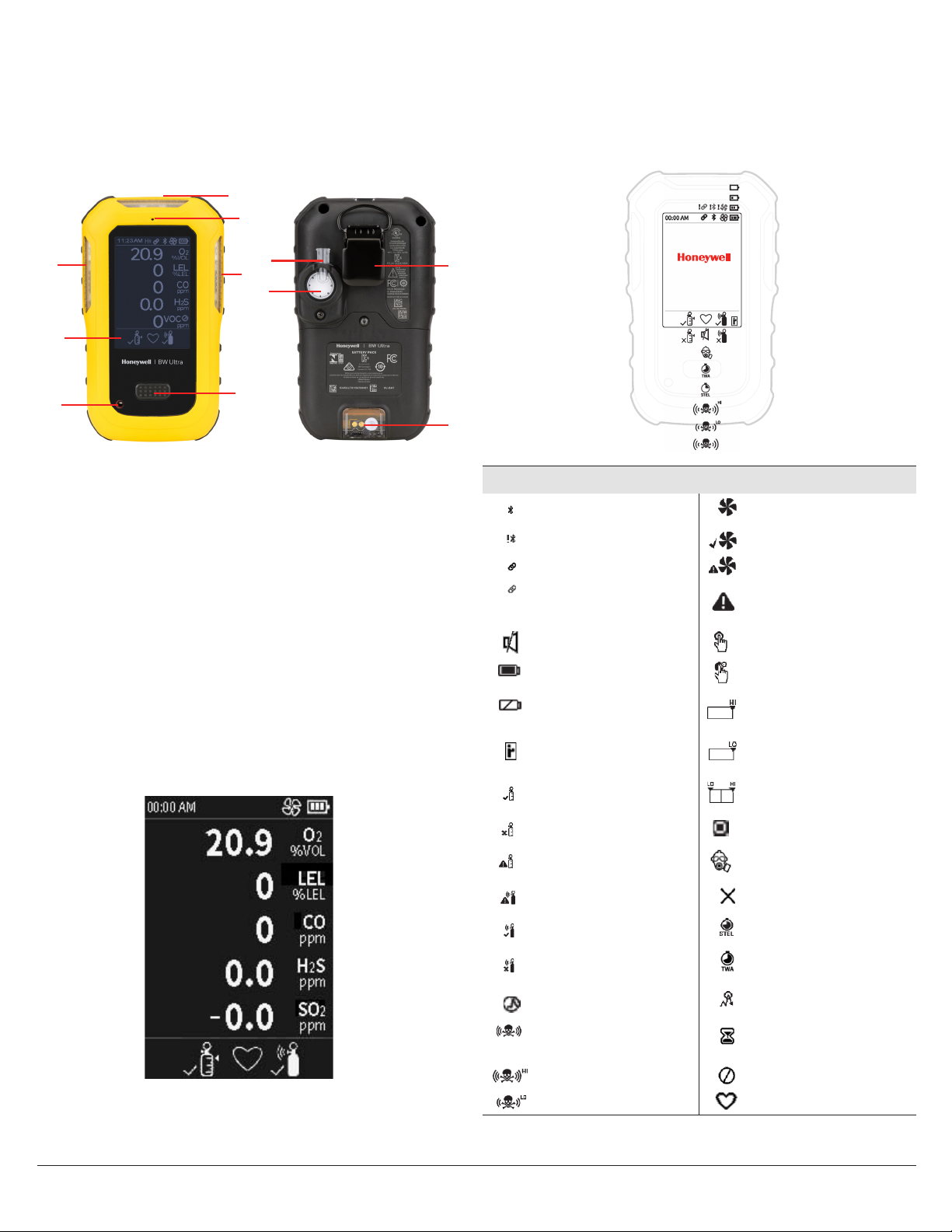
Appearance
2
Screen Icons
The detector’s screen, shown here with typical icons, will
display those shown in the following table as conditions
dictate.
6
1
8
3
4
1. Visual alarm indicator
2. Exhaust port
3. Screen
4. Button
5. Beeper Aperture
6. Pump inlet
7. Alligator clip
8. Pump assembly
9. Charging connector and IR Interface
Main Screen.
The start-up main screen is displayed as follows:
7
9
Screen Icons
BLE Pump/header
BLE Pairing Error Pump passed
Paired Pump critical fail
Pairing failed Warning/failure/
error/low battery
Stealth mode Press button
Battery -three levels Press & hold button
Low battery Hole watch mode
high
IR LINK connection Hole watch mode low
Calibration passed Hole watch Oxygen
bar
Calibration failed Target gas
Calibration cancelled Inert mode
Bump test cancelled Sensor failure
Bump test passed STEL alarm
Bump test failed TWA alarm
Correction factor Peak gas exposure
Over limit alarm Firmware update in
High alarm Sensor disabled
Low alarm Heartbeat
progress
BW Ultra User Manual4
Page 9
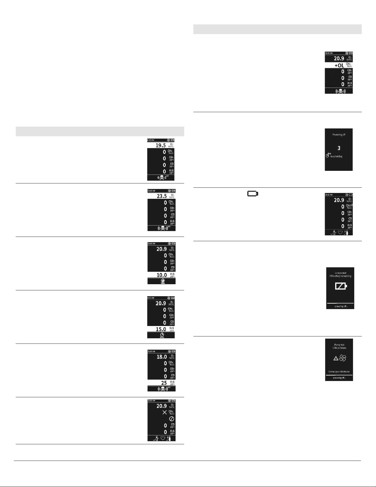
Alarms
When the detector goes into alarm, it flashes, vibrates,
and produces a loud siren noise. Depending on the type of
alarm, these flashes, vibrations, and noises will be different.
NOTE: In Stealth mode the Honeywell BW™ Ultra only
vibrates.
IMPORTANT: Regardless, when a detector goes into alarm,
always take appropriate action. Never ignore or dismiss an
alarm.
Refer to this information about the different alarm types
and their corresponding screens.
Alarm Type Description Screen
Slow siren (upward tone)
Slow flash
Low Alarm
High Alarm
Time
Weighted
Average
(TWA) Alarm
Short Term
Exposure
Limit (STEL)
Alarm
Multi Alarm
Black box around gas
flashes
Vibrator alarm activates
Fast siren (downward
tone)
Fast flash
Black box around gas
flashes
Vibrator alarm flashes
Fast siren (downward
tone)
Fast flash
Black box around gas
flashes
Vibrator alarm activates
Fast siren (downward
tone)
Fast flash
Black box around gas
flashes
Vibrator alarm activates
Alternating low and high
alarm
Black box around gas
flashes
Type of alarm alternates
Vibrator alarm alternates
Alarm Type Description Screen
Fast siren (downward
tone)
Fast flash
Over Limit
(OL) Alarm
Normal
Deactivation
Low Battery
Alarm
Critical
Battery
Alarm
Pump Alarm
Black box around gas
flashes
Vibrator alarm activates
Sequence of alternating
beeps and alternating
flashes
Vibrator alarm activates
Countdown initiates
“OFF” is displayed
Sequence of 10 rapid
sirens and alternating
flashes followed by
7 seconds of silence
(continues for 15
minutes)
Vibrator alarm pulses
After 15 minutes of
the low battery alarm
sequence, the detector
will enter critical alarm
Fifteen minutes after low
battery alarm activates,
sequence of 10 rapid
sirens and alternating
flashes with 1 second
of silence in between
(sequence reactivates
seven times)
Vibrator alarm pulses
“Low Battery Powering
Off” is displayed and the
detector deactivates
Detector is in pump alarm
when gas is turned off
during calibration.
flashes
Sensor
Failure
Alarm
BW Ultra User Manual 5
is displayed
Î
Page 10

Detector Operations
Activate the detector
Turn-on the detector in a safe area with an atmosphere of
20.9% oxygen and free of hazardous gas.
1. For first time use, charge the battery for up to 8 hours
or until LED light turns green using the charging
adapter provided. Refer to Charge the battery for more
information.
2. Press and hold the button for three seconds.
3. For first time use, a Warming sensors message is
displayed and a 30 minutes countdown is displayed.
In most cases, this countdown only lasts a couple of
minutes.
4. When the detector displays Pump test Block inlet,
block the pump inlet with a finger, and then after a
couple of seconds unblock the pump inlet.
The detector performs a quick pump test. A Pump Test
passed message is displayed.
If you do not block the pump inlet, the detector will turn
off after two minutes.
The detector will then perform a self-test, including
testing the sensors. This process could take several
minutes.
If necessary, you will be instructed by screen prompts to
calibrate newly-installed sensors.
5. When the self-test is complete, press and hold the
button to zero sensors. After the autozero is complete,
the detector then checks the sensors for calibration and
bump test.
If the detector identifies sensors requiring calibration or
bump testing, press the button and follow the on-screen
instructions.
Navigate the menu
There are four main menu items.
• See Information
• Start Bump Test
• Zero Sensors
• Start Calibration
1. Double pressing the button displays all four options on
the screen. See Information is selected and highlighted
by default.
2. Press the button to transition the selection to the next
choice.
3. Press and hold for three seconds to enter the selected
option.
4. Follow on-screen instructions for your selected
operation. Most of the detector’s procedures are
described in this guide.
View detector’s general information
1. Double-press the button to enter the main menu.
2. Select See information and press the button to scroll
through the following information:
Peak readings
STEL readings
TWA readings
Bump test intervals
Calibration
BLE information (BLE should be enabled)
LEL Correction Factor
Low Alam setpoint
Hi Alam setpoints
STEL setpoints
TWA setpoints
Activate the backlight
To activate the backlight on the screen, press the button.
Deactivate the detector
1. Press and hold the button during the powering-off
countdown.
2. Release the button when OFF is displayed.
Reset TWA or STEL readings
Before you begin.
You need to enable TWA/STEL Reset in Fleet Manager II to
reset readings in the detector.
1. Go to the main menu and select > See Information >
TWA readings or STEL readings.
2. Press and hold for 3 seconds to reset readings.
A reset message is displayed.
Reset Peak readings
Before you begin.
You need to enable Peak Reset in Fleet Manager II to reset
readings in the detector.
1. Go to the main menu and select > See Information >
Peak readings.
2. Select Hold to reset peak readings. Press and hold for 3
seconds to reset readings.
BW Ultra User Manual6
Page 11

Reset TWA/STEL and
Latching Alarms
Peak readings
Before you begin.
You need to enable TWA/STEL Reset and Peak Reset in
Fleet Manager II to reset readings in the detector.
1. Go to the main menu and select > See Information >
Peak readings.
2. Select Hold to reset all readings. Press and hold for 3
seconds to reset readings.
Zero sensors
Before you begin.
Connect the Nitrogen if this is a CO2 unit.
1. Go to the main menu and select Zero Sensors.
2. Press and hold for 3 seconds.
A Zeroing process starts automatically.
The screen displays all current gas measurements,
highlighting entries above zero.
Ambient air is applied to zero all sensors that are not
CO2.
The screen displays all current gas measurements,
highlighting entries being reset to zero.
3. If you are not zeroing O2, Click NO in the prompted
message: Is this a CO2 unit?.
Zero results are displayed.
Press the button or wait for six seconds to end the
Zeroing process.
4. Click Yes if this is a CO2 unit and you want to apply
Nitrogen to zero CO2.
A two minutes gas measure process starts
automatically.
All current gas measurements and entries reset to zero
are displayed.
5. Turn off the gas following on-screen instructions.
Zero results are displayed.
6. Press the button or wait for six seconds to end the
Zeroing process.
Zero results are displayed as follows:
• A check mark for sensors that passed Zero
• A cross mark for sensors that failed Zero
• An exclamation mark for sensors that skipped Zero
Acknowledge alarms and messages
Press and release the button to perform any of the
following:
• To acknowledge a latching alarm
• To acknowledge a low alarm
• To acknowledge due today message (for example, calibration and bump test
reminders). Note that the force calibration and force bump test features cannot
be bypassed.
If enabled, during an alarm condition the Latching Alarms
option causes the low and high gas alarms (audible, visual,
and vibrator) to persist until the alarm is acknowledged and
the gas concentration is below the low alarm setpoint. The
LCD displays the peak concentration until the alarm no
longer exists. Local regulations in your region may require
the Latching Alarms option be enabled.
The detector is shipped with the Latching Alarms option
disabled.
Calibrate the detector
Perform a calibration to adjust the sensitivity levels of
sensors and ensure accurate responses to gases.
The detector can be calibrated in two ways:
• Apply gas from a cylinder to the sensors manually through the pump inlet.
• Use an IntelliDoX module.
Before you begin. Move to a normal atmosphere (20.9%
v/v O2) that is free of hazardous gas.
1. Go to the main menu and select > Start Calibration.
2. Press and hold the button for three seconds to display
the Powering Off countdown and continue to hold for
the Starting Calibration countdown.
The detector will enter the zero function. The Zeroing
process starts automatically and lasts for five minutes.
Current gas measurements are displayed, and entries
above zero are highlighted.
3. Connect the calibration hose to the pump inlet. Make
sure to use a demand flow regulator.
4. Confirm that you want to apply Nitrogen to zero CO2.
5. When Apply calibration gas now is displayed,
apply the gas and wait for a maximum of five minutes.
The detector first tests for a specific type of gas. When
it detects enough of that gas for sensor calibration, a
check box will be displayed next to that gas. Calibration
then begins. Gas values will adjust on the screen during
the calibration.
6. When Turn gas o is displayed, disconnect the device
from gas. Check marks will be displayed next to the
calibrated sensors. These sensors reset to the number
of days until the next calibration is due (for example,
180 days).
The calibration cycle will take about two minutes after
which the user will be prompted to Press button to
continue.
7. If the calibration was successful, Calibration
Passed will be displayed. Press the button to exit
calibration.
If the calibration failed for some or all of the gases,
either a Cal Error All gases applied mixed
results message (if the detector was not successfully
BW Ultra User Manual 7
Page 12

calibrated for all gases) or a Fail all gases message
will be displayed. After the button is pressed, a Cal
overdue message will be displayed.
Start a Bump Test
Perform a bump test regularly to test sensors and alarms.
To bump test, expose the sensors to a gas concentration
that exceeds alarm setpoints and confirm that the sensors
and alarms work correctly.
The detector can be bump tested in two ways:
• Apply gas from a cylinder to the sensors manually through the pump inlet.
• Use an IntelliDoX module.
Perform a manual bump test
Before you begin.
Connect the calibration hose to a demand flow regulator on
the gas cylinder.
1. Double-press the button and select > Start Bump test.
2. Press and Hold the button for three seconds.
The detector displays Starting Bump test.
Bump test started is displayed, and then the
detector makes noise, flash, and vibrate.
3. The detector will prompt you Did you see and hear
the alarms?, select Pass, and Press and hold for
three seconds to confirm that the visual, audible, and
vibrator alarms work correctly.
An Audio-Visual test passed message is
displayed.
Skip to Step 5.
4. If the visual, audible, and vibrator alarms failed, select
Fail, and press and hold the button. An Audio-Visual
test failed message is displayed.
Then you can:
a) Apply gas, Skip to Step 5
b) Press the button to skip gas application and follow
on-screen instructions to end the Bump Test.
Bump test results are displayed, and the test ends.
5. If you want to apply gas, follow on-screen instructions.
Wait for about 30 seconds; gas measurements are
displayed for each pertinent gas sensor.
A Bump Test pass confirmation is displayed.
6. After the Turn gas o message is displayed, remove
the hose from the pump inlet. The detector will remain
in alarm until the gas clears from the sensors.
Bump test results are displayed showing check marks
next to the tested sensors. These sensors reset to the
number of days until the next Bump Test is due.
7. Press the button to finish the procedure.
Set up IntelliFlash
The IntelliFlash® feature causes the detector, if it is in
compliance (for example, bump tested and calibrated),
to flash a green light every second (the factory setting
default) from the top visual alarm indicator. In Fleet
Manager II, use the IntelliFlash Interval option to change
how often the detector flashes.
Set up Reverse IntelliFlash
IntelliFlash flashes a green light when the detector is in
compliance, but Reverse IntelliFlash® flashes an amber
light when the detector is not in compliance (a bump test
or calibration is overdue, or a sensor is not working and has
been overridden).
Use Fleet Manager II to change how often the detector
flashes for Reverse IntelliFlash.
IntelliFlash and Reverse IntelliFlash can be configured in
one of four scenarios:
Scenario 1
When both IntelliFlash and Reverse IntelliFlash are
enabled, the detector’s green LED will flash until it goes out
of compliance, then its amber LED will flash instead.
Scenario 2
If IntelliFlash is enabled and Reverse IntelliFlash is
disabled, the detector’s green LED flashes until it goes out
of compliance, then it stops flashing.
Scenario 3
If IntelliFlash is disabled and Reverse IntelliFlash is
enabled, neither LED will flash while the detector is in
compliance. The amber LED will flash if it goes out of
compliance.
Scenario 4
When both IntelliFlash and Reverse IntelliFlash are
disabled, neither LED will flash under any circumstances.
Set up the Confidence and
Compliance Beep interval
The Confidence Compliance Beep is a sound that tells
the user the detector is in compliance (for example,
bump tested and calibrated). In Fleet Manager II use the
Confidence/Compliance Beep option to change how often
the detector beeps for Confidence Compliance Beep.
a CAUTION
Honeywell recommends to bump test the sensors before each day’s
use to confirm their ability to respond to gas by exposing the sensors
to a gas concentration that exceeds the alarm setpoints.
BW Ultra User Manual8
Page 13

Select an operation mode
The detector can be used in one of three modes: Essentials
mode, Hole Watch mode, and Inert mode.
Note: Honeywell BW™ Ultra always monitors gas levels, regardless of
the operating mode. If the detector detects a sudden gas exposure,
it will flash, vibrate, and produce a loud siren noise. A gas level alarm
takes precedence over all of the detector’s other functions.
Configure the Detector
You can configure the Honeywell BW™ Ultra detector’s
device and sensor using Fleet Manager II.
Necessary to configure detector settings:
• Honeywell BW™ Ultra detector
• IR Link adapter or IntelliDoX docking station
• Computer with Fleet Manager II software installed.
Essentials mode
The detector only shows the gas readings.
Hole Watch mode
The Hole Watch mode is the default operating mode. It is
used for confined space monitoring. Use Hole Watch mode
to monitor all gas levels in the same screen view. Hole
Watch mode uses bar graphs that fill when the detector
detects rising gas concentrations.
• When the detector detects normal gas levels, Hole Watch mode displays
empty bar graphs.
• When the detector detects non-critical gas levels, Hole Watch mode displays
filling bar graphs.
• When the detector activates a single gas alarm, Hole Watch mode highlights
the detected gas level for that gas in a solid bar.
• When the detector activates a multiple gas alarm, Hole Watch mode continues
to display the first detected gas level, as well as highlight other detected gas
levels in a solid bar.
• For oxygen, Hole Watch mode displays low and high levels in a bar graph. As
the detector detects a low oxygen level, the bar graph fills toward LO.
• As the detector detects a high oxygen level, the bar graph fills toward HI.
Inert mode
You can configure Inert Mode in Fleet Manager II. The
threshold for operation is 10%. If oxygen readings fall
below 10%, the detector prompts the user to enter the Inert
mode. The detector does not start automatically in Inert
Mode.
When the detector goes into Inert Mode, the alarms
setpoint get activated. If the detector does not enter in Inert
mode, The O2 readings are considered normal.
For device settings, a startup message can be added;
Confidence Compliance Beep can be activated, bump tests
can be forced, stealth mode can be enabled, etc.
For sensor settings, the calibration gas type and frequency
can be changed, the bump test interval and alarm setpoints
can be set, STEL and TWA can be selected, etc.
You can perform some other calibrations with Fleet
Manager II.
Note: When the operator configures the Honeywell BW™ Ultra using
FleetManager II, Honeywell strongly recommends reviewing the
detector’s settings before the operation to ensure that settings were
applied successfully and comply with performance requirements.
Custom configuration created in Fleet Manager II can be
used to configure detector settings.
Example: Five detectors must have the same bump test
reminders and alarm setpoints. Each detector could be
configured separately or Fleet Manager II can be utilized to
create a custom settings configuration. This configuration
can then be loaded on each detector. This saves time and
allows settings to be managed from one location.
Connect With IntelliDoX
If a detector’s calibration is overdue and the forced
calibration feature is enabled, the calibration can be
performed with an IntelliDoX docking station or through
the calibration option from the detector’s main menu.
Connect With an IR Link
The detector can be paired with an IR link, aka dongle.
There is an IR connection at the bottom of the detector
that allows FleetManager II configurations to be efficiently
transferred to multiple detectors. The IR link will also allow
new firmware to be transferred to detectors or data/event
logs to be transferred to FleetManager II.
Note: You should have the IR Connectivity Kit (sold separately) to
transfer the data from a computer to the detector.
BW Ultra User Manual 9
Page 14

Bluetooth Pairing
The user can pair the Honeywell BW™ Ultra to a mobile
device via built in Bluetooth Low Energy (BLE). The
Honeywell Safety Communicator app, installed on the
mobile phone, can then show gas readings and alarms
from the Honeywell BW™ Ultra unit that is connected.
Readings and alarms can then be sent to Honeywell’s
remote monitoring software.
1. On the mobile device, turn on the Bluetooth connection
and look for available detectors.
On the Honeywell BW™ Ultra, the Bluetooth connection
is on by default.
2. On the mobile device, select the detector and then enter
100000.
Note: Pairing is not allowed at start up, during calibration, or bump
test.
Warning: Wireless communication and infrastructure
should be used as informational monitoring only.
Replace a Sensor
Use only sensors designed by Honeywell for the
Honeywell BW™ Ultra detectors. Replace the sensors in a
non-hazardous location.
The Honeywell BW™ Ultra detector can be configured for a
maximum of 5 gases and may contain dummy sensors.
Review Logs
Many of the detector events are logged and can be
reviewed via IntelliDoX or BLE. Typical logged events would
be:
• bump test failed • self-test failed
• last calibration failed • calibration overdue
• calibration forced • calibration canceled
• calibration error • calibration passed
• sensors in alarm • system reset
• sensors zeroed • event logs vs. data logs
• “Turn cal gas off...” message is displayed
BW Ultra User Manual10
Page 15

Maintenance
Maintenance
Perform the following tasks to maintain the detector in
good operating condition:
• Calibrate, bump test, and inspect the detector on a regular schedule.
• Maintain an operations log of all maintenance, bump tests, calibrations, and
alarm events.
• Keep the exterior of the detector clean.
Gas Cylinder Guidelines
• Use a premium-grade calibration gas that is approved by the National Institute
of Standards and Technology.
• Verify the expiration date on the cylinder before use.
• Do not use an expired gas cylinder.
• Contact Honeywell if a certified calibration of the detector is required.
Languages
Honeywell BW™ Ultra supports eight languages: English,
French, German, Portuguese, Spanish, Simplified Chinese,
Russian, Italian, Dutch, Slovak, Czech, Polish, Norwegian,
Danish, Swedish, Finnish, Turkish, and Arabic.
These are configurable through FleetManager II.
Custom startup text can be entered in all languages except
Simplified Chinese through FleetManager II.
Clean the Detector
Clean the exterior of the detector with a soft, damp cloth.
Use only water-based (non-alcohol) cleaners. Do not use
soaps, solvents, or polishes.
Upgrade the Firmware
Upgrade the Firmware via IR Link using the Fleet Manager
II Software.
Charge the Battery
You can charge the battery using the provided charging
adapter, that is certified for SELV/LVLC (isolated) with an
output Um of 6.3 V.
It can take up to 8 hours to get the battery fully charged in a
temperature range from 5 °C to 35 °C.
Note: If you charge with the power on, charging may not be completed
within 8 hours.
Maintain the Battery
Lithium-ion batteries do not respond well to cycles of full
discharge followed by a full charging cycle. Recharge the
battery before it is exhausted.
Do not charge the battery at low or elevated temperatures.
30°C (86ºF) is considered an elevated temperature and
should be avoided whenever possible.
A rechargeable battery’s runtime decreases approximately
20% over a two-year period of typical use.
Real Time Clock Display
The real time clock is displayed in the upper left corner
of the detector’s screen. It is configurable through
FleetManager II in 12 or 24-hour formats.
The date display can also be configured in several formats
through FleetManager II.
The time/date information is retained even when the
detector’s battery is being changed.
Before you begin.
• You should have the IR Connectivity Kit (sold separately) to transfer the data
from a computer to the detector.
• Download and save the firmware update file to a PC or network drive.
Do not rename the file.
• Download the BWFleetManager2.exe file and install Fleet Manager II.
• For more information refer to the Fleet Manager II User Manual.
1. Turn on the detector.
2. Start Fleet Manager II application.
a) Expand Administration from the left pane.
b) Click Login/Logout.
c) Type in the default password: Admin.
d) Click OK to continue.
3. In the left pane select Devices > Configure device via IR
link.
In the Device Selection window:
a) Select Honeywell BW™ Ultra.
b) Click OK.
4. In the Honeywell BW™ Ultra configuration window, click
Bootloader to select the binary file.
In the Honeywell BW™ Ultra Bootloader window, click
Choose File.
5. In the Choose Firmware File to Upload window, select
the downloaded file, and then click Open.
6. Connect the Honeywell BW™ Ultra detector to the
computer using the IR Link connector.
7. Click Send to initiate the file transfer to the gas detector.
After the file transfer is complete, the Bootload process
will start. During Bootload, the display will go blank and
the detector will beep several times.
8. The Programming Succeeded message is displayed.
Press the button to finish the procedure, and then
disconnect the detector from the computer.
BW Ultra User Manual 11
Page 16

Service
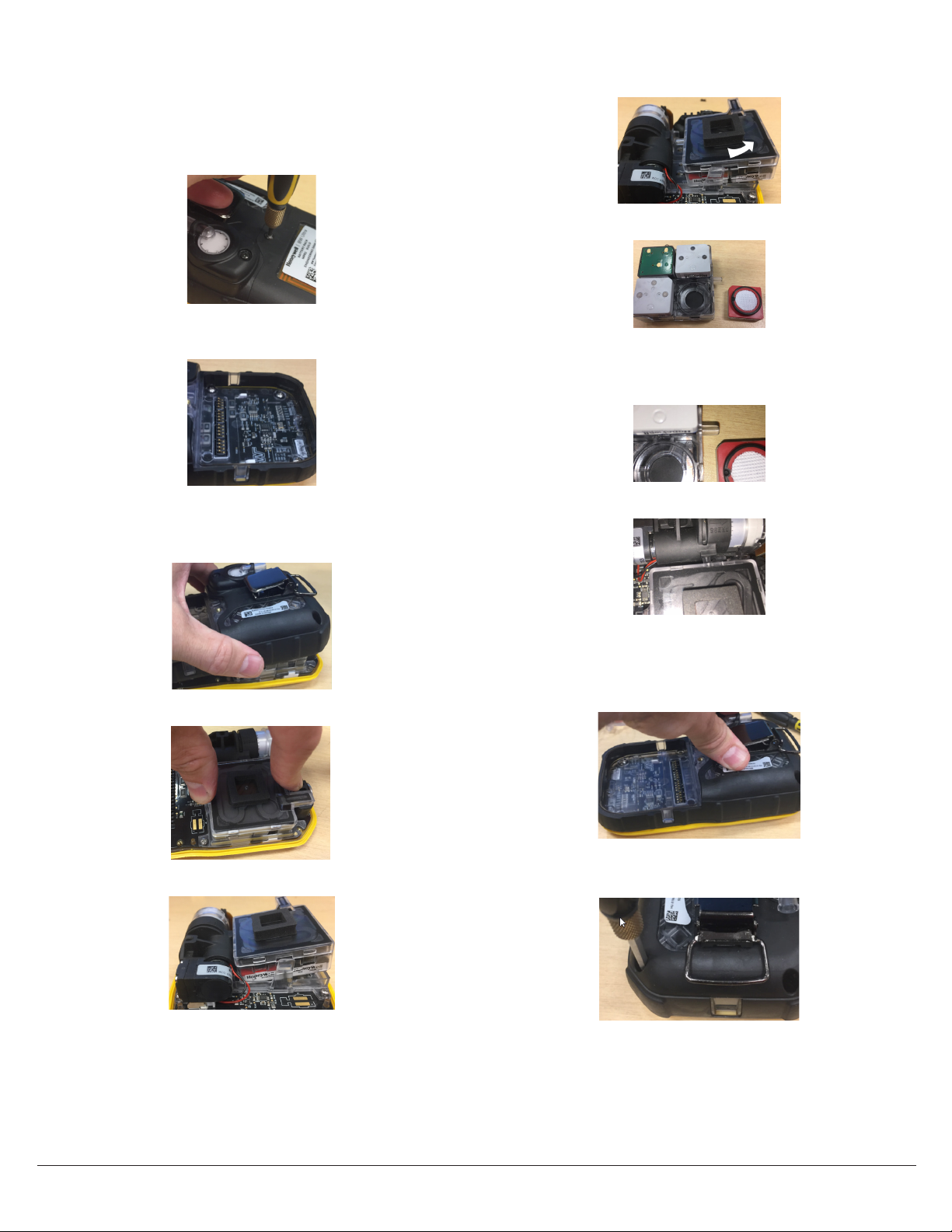
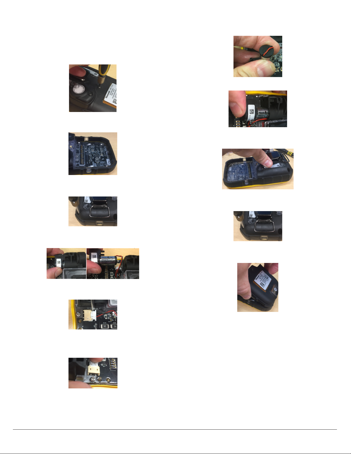
Replace the Printed Circuit Board
(PCB)
3. Remove the LCD:
a) Disengage the two snaps on the upper sides of the
LCD carrier.
1. Turn the instrument off.
2. Remove the front shell:
a) Turn the instrument face down and unscrew on the
battery pack.
b) Remove the battery pack and the four screws in the
battery compartment.
c) Remove the two screws at the top of the instrument
and pull the back shell apart from the front shell.
b) Swing LCD forward watching for the ZIF connector.
c) Lift the latch on the ZIF connector, and then pull the
LCD cable forward and remove LCD assembly.
4. Disengage the two snaps holding the manifold carrier
in place and carefully pull up the manifold carrier off the
PCB.
d) Remove the two screws holding the PCBA in place.
e) Remove the PCB assembly from the front shell.
5. Lift the latch on the 4R+ ZIF connector and pull out the
4R+ cable assembly to disconnect the pump connector
from the PCB.
6. Retrieve the new PCB.
7. Connect the pump to the PCB.
8. Align the snaps on the manifold carrier and push down
to engage the snaps to the PCB.
BW Ultra User Manual12
Page 17

9. Insert the 4R+ ribbon cable into the ZIF connector and
press down on the 4R+ ZIF latch to engage the cable.
10. Re-connect the 4R+ sensor cable.
b) Place the PCB into the front shell and insert the two
screws (torque 34 in-lbs) to fasten both pieces.
c) Replace the back shell and install the four screws
back into the battery compartment (torque 45 in-lbs).
11. Attach the LCD:
a) Insert the LCD ribbon cable into the ZIF connector
and press down on the ZIF connector latch to engage
the cable.
b) Lever the LCD assembly back toward the PCB, then
press down until the side snaps are engaged.
12. Attach the shells:
a) On the front shell, ensure the LCD gasket is aligned
with the pins. The frame should be facing up.
d) Reinstall the two screws at the top of the instrument
(torque 45 in-lbs).
13. Place the battery pack:
a) Engage hooks on the bottom of the battery pack.
b) Push the battery pack into place.
c) Tighten the battery retention screw (torque 45 inlbs).
14. Turn on the instrument and allow for the sensors to
stabilize.
Calibrate sensors.
BW Ultra User Manual 13
Page 18

Replace the LCD
1. Turn the instrument off.
2. Remove the battery:
a) Turn the instrument face down and unscrew on the
battery pack.
b) Remove the battery pack and the four screws in the
battery compartment.
3. Remove the front shell:
a) Remove the two screws at the top of the instrument
and pull the back shell apart from the front shell.
4. Remove the LCD:
a) Disengage the two snaps on the upper sides of the
LCD carrier.
b) Swing LCD forward watching for the ZIF connector.
c) Lift the latch on the ZIF connector, pull the LCD cable
forward and remove LCD assembly to remove the LCD
assembly.
b) Remove the two screws holding the PCB in place.
c) Remove the PCB assembly from the front shell.
d) Pull the LCD cable forward and remove the LCD
assembly.
5. Retrieve the new LCD.
6. Attach the LCD:
a) Insert the LCD ribbon cable into the ZIF connector
and press down on the ZIF connector latch to engage
the cable.
b) Lever the LCD assembly back towards the PCB, then
press down until the side snaps are engaged.
BW Ultra User Manual14
Page 19

c) On the front shell, ensure the LCD gasket is aligned
with the pins. The frame should be facing up.
7. Attach the front shell:
a) Place the PCB into the front shell and insert the two
screws (torque 34 in-lbs) to fasten both pieces.
b) Replace the back shell and install the four screws
back into the battery compartment (torque 45 in-lbs).
b) Push the battery pack into place and tighten the
battery retention screw (torque 45 in-lbs).
c) Turn on the instrument and allow for the sensors to
stabilize.
c) Reinstall the 2 screws at the top of the instrument
(torque 45 in-lbs).
8. Attach the battery:
a) To place the battery pack correctly, first engage
hooks on the bottom of the battery pack.
BW Ultra User Manual 15
Page 20
Replace the 1-Series Sensors
1. Turn the instrument off.
2. Remove the battery:
a) Turn the instrument face down and unscrew on the
battery pack.
b) Remove the battery pack and the four screws in the
battery compartment.
3. Remove the sensor:
a) Remove the two screws at the top of the instrument
and pull the back shell apart from the front shell.
d) Pull the sensor manifold out from the pump
manifold.
e) Remove the desired sensor.
4. Install the new sensor:
a) Mind the orientation key, and then push the sensor
down into manifold.
b) Insert manifold inlet into pump manifold.
b) Pull back the two retaining clips on the manifold.
c) Lift the manifold sideways, farthest from the pump.
c) Push manifold down and as the two latches engage,
listen for two snapping sounds.
5. Replace the back shell and install the four screws back
into the battery compartment (torque 45 in-lbs).
6. Reinstall the 2 screws at the top of the instrument
(torque 45 in-lbs).
BW Ultra User Manual16
Page 21

7. Attach the battery:
a) To place the battery pack correctly, first engage
hooks on the bottom of the battery pack.
b) Push the battery pack into place and tighten the
battery retention screw (torque 45 in-lbs).
8. Turn on the instrument and allow for the sensors to
stabilize.
BW Ultra User Manual 17
Page 22

Replace the 4R+ Sensors
1. Turn the instrument off.
2. Remove the battery:
a) Turn the instrument face down and unscrew on the
battery pack.
b) Remove the battery pack and the 4 screws in the
battery compartment.
3. Remove the sensor:
a) Remove the two screws at the top of the instrument
and pull the back shell apart from the front shell.
4. Install the new sensor:
a) Retrieve the new sensor and insert it into the
manifold aligning the sensor guides to the instrument’s
slots.
b) Push sensor forward until it stops moving.
c) Re-connect the 4R+ sensor cable.
5. Replace the back shell and install the four screws back
into the battery compartment (torque 45 in-lbs).
b) Disconnect the 4R+ cable from the sensor.
c) Push at the PRESS marking in the manifold toward
the top of the instrument.
d) Use the tabs on the sensor to pull it out of the
manifold.
Reinstall the two screws at the top of the instrument
(torque 45 in-lbs).
6. To place the battery pack correctly, first engage hooks
on the bottom of the battery pack.
7. Push the battery pack into place and tighten the battery
retention screw (torque 45 in-lbs).
8. Turn on the instrument and allow for the sensors to
stabilize.
9. Calibrate new sensor.
BW Ultra User Manual18
Page 23
Replace the Pump
1. Turn the instrument off.
2. Remove the battery:
a) Turn the instrument face down and unscrew on the
battery pack.
b) Remove the battery pack and the four screws in the
battery compartment.
3. Remove the two screws at the top of the instrument and
pull the back shell apart from the front shell.
b) Fold the pump wires across the bottom of the pump
motor.
c) Insert the pump into the manifold assembly.
6. Replace the back shell and install the 4 screws back into
the battery compartment (torque 45 in-lbs).
7. Reinstall the two screws at the top of the instrument
(torque 45 in-lbs).
4. Remove the pump:
a) Pull the pump out of the manifold assembly.
b) Release the pump connector retainer clip and pull the
pump connector out.
5. Install the new pump:
a) Retrieve the new pump and insert the pump
connector.
8. To place the battery pack correctly, first engage hooks
on the bottom of the battery pack.
9. Push the battery pack into place and tighten the battery
retention screw (torque 45 in-lbs).
BW Ultra User Manual 19
Page 24
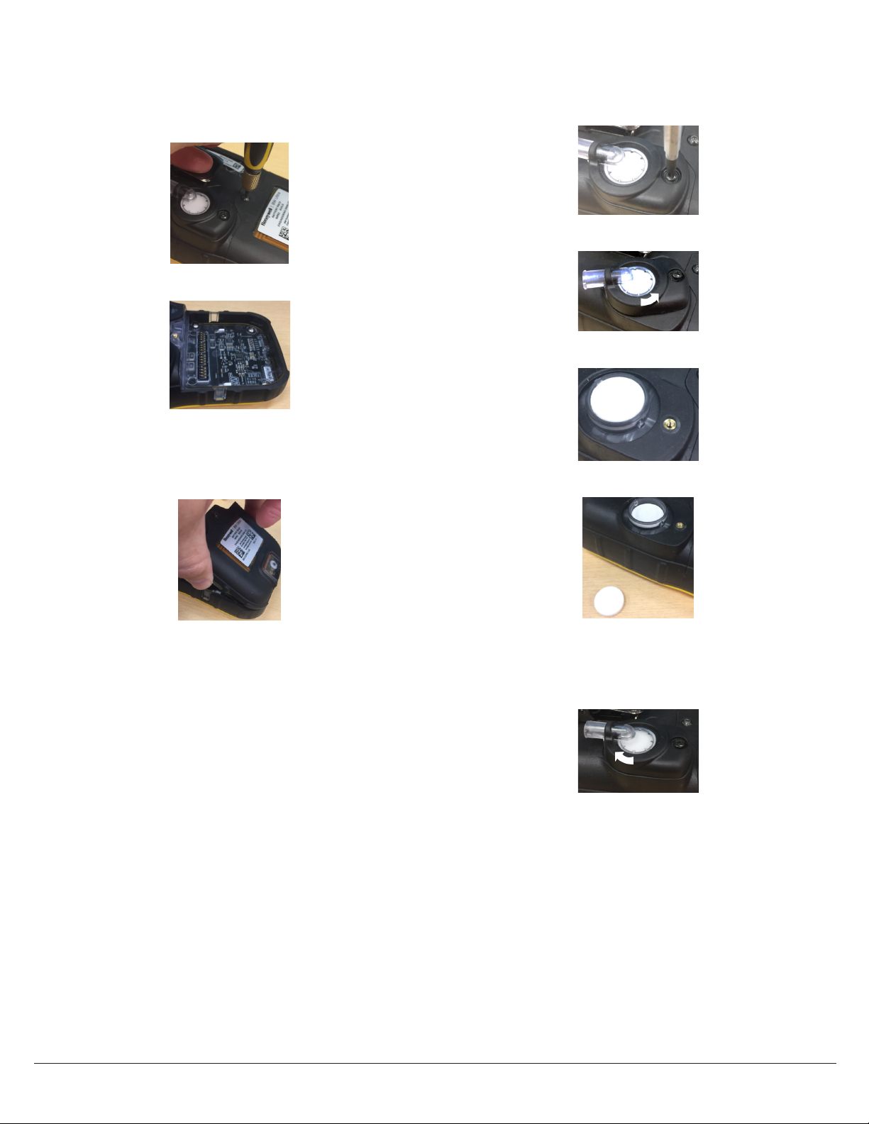
Replace the Battery
Replace the Pump Inlet Filter
1. Turn the instrument off.
2. Turn the instrument face down and unscrew on the
battery pack.
3. Remove the battery pack.
4. To place the new battery pack correctly, first engage
hooks on the bottom of the battery pack.
5. Push the battery pack into place and tighten the battery
retention screw (torque 45 in-lbs).
1. Turn the instrument off.
2. Unthread the screw on the pump inlet cover.
3. Rotate the cover counter-clockwise.
4. Remove the cover.
5. Remove both the particulate and hydrophonic filter.
Note: Use only the HU-BAT Honeywell battery pack.
6. First, Install both the hydrophonic and then the
particulate filters.
7. Place the filter cover and rotate the filter cover clockwise
until stop.
8. Tighten the screw (torque to 34 in-lbs).
BW Ultra User Manual20
Page 25

Appendices
Auto detect gas
While the gas is applied during calibration, the detector will
wait for up to 300 seconds to allow the gas to stabilize. If
the gas has not stabilized by then, the detector will display
a Gas unstable message. If the gas stabilizes within
300 seconds, it will be automatically detected and will not
have to be selected from a menu. The name of the gas and
a Span calibration in progress message will be
displayed. If a quad gas mixture was used, the detector will
display the names of all four gases.
Gas Alarm Setpoints
Gas alarms are activated when detected gas concentrations
are above or below the user-defined setpoints. The gas
alarms are described as follows.
Alarm Condition
Low Toxics and combustibles: Ambient gas level
above low alarm setpoint.
Oxygen: Ambient gas level may be set above or
below 20.9% (or 20.8%).
High Toxics and combustibles: Ambient gas level
above high alarm setpoint.
Oxygen: Ambient gas level may be set above or
below 20.9% (or 20.8%).
TWA Toxics only: Accumulated value above the TWA
alarm setpoint.
STEL Toxics only: Accumulated value above the STEL
alarm setpoint.
Multi-gas Two or more gas alarm conditions
simultaneously.
Over Limit (OL) OL or OL displays when readings are above or
below the sensor detection range, respectively.
Specifications
Detector dimensions: 8.1 x 14.6 x 5.1cm
Weight: 444.2 g
Operating temperatures: 4°F to +122°F (20°C to +50°C)
Battery operating times: 10 hours.
Rechargeable battery: 8 hours in a temperature range
from 5 °C to 35 °C.
Storage temperature: 40°F to +122°F (40°C to +50°C)
Operating humidity: 0% to 95% relative humidity
(non-condensing)
Detection range:
H2S: 0 – 100 ppm (1 / 0.1 ppm increments)
CO: 0 – 500 ppm (1 ppm increments)
O2: 0 – 30.0% vol. (0.1% vol. increments)
Combustible (LEL): 0% to 100% LEL (1% LEL
increments) or 0.0% to 5.0% v/v methane
Sensor type:
Alarm conditions: STEALTH, TWA alarm, STEL alarm, low
alarm, high alarm, multi-gas alarm, low battery alarm,
confidence beep, automatic deactivation alarm
Audible alarm: 95 dB at 30 cm (1 ft.) (100 dB typical)
variable pulsed beeper
Visual alarm: Red light-emitting diodes (LED)
Display: Alphanumeric liquid crystal display (LCD)
Screen resolution: 160X240 pixels.
Backlight: Activates when the pushbutton is pressed and
deactivates after 5 seconds; also activates during an alarm
condition
Self-test: Initiated upon activation.
Calibration: Automatic zero and automatic span.
Sample Factory Alarm Setpoints
Following table lists alarm setpoints as defined by the US
Occupational Safety and Health Association (OSHA).
Gas TWA STEL Low High
H2S 10 ppm 15 ppm 10 ppm 15 ppm
CO 35 ppm 50 ppm 35 ppm 200 ppm
O2 N/A N/A 19.5% vol. 23.5% vol.
LEL N/A N /A 10% LEL 20% LEL
Note: To disable an alarm, set the alarm setpoint to 0 (zero) in Fleet
Manager II.
BW Ultra User Manual 21
Page 26

Standards and Certifications
The Honeywell BW™ Ultra gas detector is in conformity with
the following standards and certifications:
IECEx: UL 18.0061X
IEC 600790:2017
IEC 6007911:2011
IEC 600791:2014
Approvals:
Approved by UL to both U.S. and Canadian Standards
UL 913, 8th Edition
UL 600790, 6th Edition
UL 600791, 7th Edition.
UL 6007911, 6th Edition
ANSI/ISA 60079291 (12.13.01) - 2013
CSA C22.2 No.152M1984 (R2016)
CSA C22.2 No. 600790:15
CSA C22.2 No. 6007911:14
CSA C22.2 No. 600791:16
UL: E480011
Class I, Division I, Group A, B, C and D, Temperature code
T4, 40 ≤ Tamb ≤ +50°C
Class I, Zone 0, AEx ia IIC T4 Ga, 40 ≤ Tamb ≤ +50°C
(without LEL and IR sensor installed)
Class I, Zone 0, AEx da ia IIC T4 Ga, 40 ≤ Tamb ≤ +50°C
(with LEL sensor installed and without IR sensor installed)
Class I, Zone 0, AEx ia IIC T4 Ga, 20°C ≤ Tamb ≤ +50°C
(with IR sensor installed and without LEL sensor installed)
Class I, Zone 0, AEx da ia IIC T4 Ga, 20°C ≤ Tamb ≤ +50°C
(with LEL and IR sensor installed)
CSA: E480011
Class I, Division I, Group A, B, C and D, Temperature code
T4, 40 ≤ Tamb ≤ +50°C
Ex ia IIC T4 Ga, 40 ≤ Tamb ≤ +50°C
(without LEL and IR sensor installed)
Ex da ia IIC T4 Ga, 40 ≤ Tamb ≤ +50°C
(with LEL sensor installed and without IR sensor installed)
Ex ia IIC T4 Ga, 20°C ≤ Tamb ≤ +50°C (with IR sensor
installed and without LEL sensor installed)
Ex da ia IIC T4 Ga, 20°C ≤ Tamb ≤ +50°C (with LEL and IR
sensor installed)
ATEX: DEMKO 18 ATEX 1833X
EN IEC 600790:2018
EN 6007911:2012
EN 600791:2014
I M1 Ex ia I Ma, II 1 G Ex ia IIC T4 Ga, 40°C ≤ Tamb ≤ +50°C
(without LEL and IR sensor installed)
I M1 Ex da ia I Ma, II 1 G Ex da ia IIC T4 Ga, 40°C ≤ Tamb ≤ +50°C
(with LEL sensor installed and without IR sensor installed)
I M1 Ex db ia I Ma, II 2 G Ex db ia IIC T4 Gb, 20°C ≤ Tamb ≤ +50°C
(with IR sensor installed)
Ex ia I Ma, Ex ia IIC T4 Ga, 40°C ≤ Tamb ≤ +50°C
(without LEL and IR sensor installed)
Ex da ia I Ma, Ex da ia IIC T4 Ga, 40°C ≤ Tamb ≤ +50°C
(with LEL sensor installed and without IR sensor installed)
Ex db ia I Ma, Ex db ia IIC T4 Gb, 20°C ≤ Tamb ≤ +50°C
(with IR sensor installed)
The following additional previous editions of Standards
noted under the “Standards” section of this Certificate
were applied to integral Components as itemized below.
There are no significant safety related changes between
these previous editions and the editions noted under the
“Standards” section.
Product Certificate Num Standards
Dynament Ltd.
Gas Sensors Type
MSH2ia***
City Technology
Limited, Miniature
Combustible Gas
Sensor - 1 LEL 75
FCC Compliance
This device complies with part 15 of the FCC Rules.
Operation is subject to the following two conditions:
(1) This device may not cause harmful interference, and
(2) this device must accept any interference received,
including interference that may cause undesired operation.
This transmitter must not be co-located or operated in
conjunction with any other antenna or transmitter. This
equipment complies with FCC radiation exposure limits
set forth for an uncontrolled environment. End users must
follow the specific operating instructions for satisfying RF
exposure compliance.
NOTE: This equipment has been tested and found to
comply with the limits for a Class A digital device, pursuant
to part 15 of the FCC Rules. These limits are designed to
provide reasonable protection against harmful interference
when the equipment is operated in a commercial
environment. This equipment generates, uses, and can
radiate radio frequency energy and, if not installed and
used in accordance with the instruction manual, may cause
harmful interference to radio communications. Operation
of this equipment in a residential area is likely to cause
harmful interference in which case the user will be required
to correct the interference at his own expense.
IECEx FTZU
15.0002U
IECEx ULD
16.0016U
IEC 600790
Edition 2011
IEC 600790
Edition 2011
BW Ultra User Manual22
Page 27

CAUTION
Changes or modifications not expressly approved by the
manufacturer responsible for compliance could void the
user’s authority to operate the equipment.
This device complies with FCC radiation exposure limits
set forth for an uncontrolled environment and meets the
FCC radio frequency (RF) Exposure Guidelines. This device
has very low levels of RF energy that it is deemed to comply
without maximum permissive exposure evaluation (MPE).
RED Compliance
Honeywell Analytics Asia Pacific Co., Ltd. hereby declares
that this gas detector, Honeywell BW™ Ultra, is in
compliance with the essential requirements and other
relevant provisions of Directive 2014/53/EU.
Canada, Industry Canada (IC) Notices
This device complies with Industry Canada license-exempt
RSS. Operation is subject to the following two conditions:
(1) this device may not cause interference, and
(2) this device must accept any interference, including
interference that may cause undesired operation of the
device.
This device complies with FCC/ISED radiation exposure
limits set forth for an uncontrolled environment and meets
the FCC/ISED radio frequency (RF) Exposure Guidelines.
This device has very low levels of RF energy that it is
deemed to comply without maximum permissive exposure
evaluation (MPE).
For the compliance of CSA C22.2 No.152 and ISA 60079
291, the adjustable alarm point shall not exceed 60 %
LEL and the highest alarm shall be configured as latching
alarm.
In ISA 60079291, Honeywell BW™ Ultra was tested only
for IP54. Other IP ratings are not the scope of ISA 60079
291. Honeywell BW™ Ultra was pressure tested for 80, 100
and 120 kPa in ISA 60079291. Outside of 80 - 120 kPa is
NOT the scope of ISA 60079291.
Canada, avis d’Industrie Canada (IC)
Cet appareil est conforme aux normes RSS exemptes de
licence d’Industrie Canada. Son utilisation est soumise aux
deux conditions suivantes :
(1) cet appareil n’engendre pas d’interférences, et
(2) cet appareil doit tolérer tout type d’interférences,
notamment les interférences pouvant provoquer une
utilisation non désirée de l’appareil.
Cet équipement est conforme aux limites établies par FCC/
Industrie Canada en matière d’exposition aux radiations
dans un environnement non contrôlé. Cet équipement ne
doivent pas être colocalisés ou fonctionner en conjonction
avec tout autre antenne ou émetteur.
In terms of North America flammable gas performance
approval:
Honeywell BW™ Ultra is approved for ISA 60079291 and
CSA C22.2 No.152.
Only Honeywell BW™ Ultra catalytic bead flammable sensor
was evaluated for CSA C22.2 No.152 and ISA 60079291.
The evaluation is valid only with the pumping flow rate 300
ml/min, 3 m length tube and CH4 (Methane) gas.
The other options are not the scope of CSA C22.2 No.152
and ISA 60079291.
BW Ultra User Manual 23
Page 28

Label Information
1
2
5
6
7
3 4
BW Ultra Battery label
cULus ATEX IECEx
4321
BW Ultra Instrument label
1
2
3
7
8
9
4
10
cULus
5
1. BW Ultra battery serial number and2D
barcode
2. Manufacturer information
3. CEC battery charging system approval
marking
4. WEEE marking
5. Chinese EPUP marking
5
1. cULus certificate marking
2. Class Division protection marking
3. Class Zone protection markingwhen BW Ultra is
configured without LEL and IR sensor
6
4. Class Zone protection markingwhen BW Ultra is
configured with LEL and without IR sensor
5. Class Zone protection marking when BW Ultra is
configured with IR sensor and without LEL sensor
6. Class Zone protection marking when BW Ultra is
configured with IR sensor and with LEL sensor
7. North America flammable performance approval
8. FCC and IC certificate number
9. BW Ultra part number and 2D barcode
10. BW Ultra serial number and 2D barcode
ATEX
1. ATEX QAN notified body number
2. ATEX protection markingwhen BW Ultra is
configured without LEL and IR sensor
3. ATEX protection markingwhen BW Ultra is
configured with LEL and without IR sensor
4. ATEX protection markingwhen BW Ultra is
configured with IR sensor
5. ATEX certificate number
6. BW Ultra part number and 2D barcode
24
7. BW Ultra serial number and 2D barcode
BW Ultra User Manual
Page 29

IECEx
1
Ex ia I Ma,
Ex ia IIC T4 Ga
-40°C ≤ Tamb ≤ +50°C
Ex ia I Ma,
Ex ia IIC T4 Ga
2 3
-40°C ≤ Tamb ≤ +50°C
Ex ia I Ma,
Ex ia IIC T4 Ga
-40°C ≤ Tamb ≤ +50°C
1. IECEx protection markingwhen BW Ultra is
configured without LEL and IR sensor
2. IECEx protection markingwhen BW Ultra is
configured with LEL and without IR sensor
4
3. IECEx protection markingwhen BW Ultra is
configured with IR sensor
4. IECEx certificate number
5. BW Ultra part number and 2D barcode
5
6
6. BW Ultra serial number and 2D barcode
Part Number Format
BW Ultra’s explosion-proof protection type varies per the sensor configuration.
The user can notice the sensor configuration with the part number format.
HU
W1: 1 LEL 75 sensor
W2: 1 LEL 75C sensor
W3: 1 LEL 75M sensor
00: Dummy sensor
X1: Oxygen sensor
00: Dummy sensor
M1: CO sensor
00: Dummy sensor
H1: H2S sensor
00: Dummy sensor
1 digit of alphabet: country code
Y: Yellow enclosure
B: Black enclosure
Q1: PID sensor
W4: LEL IR sensor
B1: CO2 IR sensor
S1: SO2 sensor
A1: NH3 sensor
R1: H2 sensor
C1: Cl2 sensor
D1: NO2 sensor
Z1: HCN sensor
N1: NO sensor
M2: COH sensor
00: Dummy sensor
BW Ultra User Manual
25
Page 30

Troubleshooting
Problem Probable Cause Solution
Detector does not display normal gas reading
after startup sequence
Detector does not respond to button
Detector does not accurately measure gas
Detector does not enter alarm
Detector intermittently enters alarm without
reason
Features and options are not operating as
expected
Battery has been charging for hours.
Charging indicator on LCD shows the battery is
still charging
Battery indicator does not display when
charging
Battery does not charge Replace the battery.
Sensor fails to zero during startup self-test Change the sensor.
The detector does not activate. Depleted battery. Replace the battery.
Detector automatically deactivates. Automatic deactivation due to critical low
Sensor not stabilized
Sensor requires calibration Calibrate the detector.
Target gas is present Detector is operating properly. Use caution in suspect areas.
Battery is in critical low battery state or is
completely depleted
Detector is performing operations that do
not require user input
Sensor requires calibration Calibrate the detector.
Detector is colder/hotter than gas
temperature
Sensor filter is blocked Clean the sensor filter.
Alarm setpoint(s) are set incorrectly Reset the alarm setpoints.
Alarm setpoint(s) set to zero Reset the alarm setpoints.
Detector is in calibration mode Complete calibration.
Ambient gas levels are near alarm setpoint
or the sensor is exposed to a puff of
hazardous gas
Alarm setpoints are set incorrectly Reset the alarm setpoints.
Detector requires calibration Calibrate the detector.
Missing or faulty sensor Change the sensor.
Changes in Fleet Manager II Verify the setup in Fleet Manager II.
Battery is trickle charging Verify the charger is properly connected to the AC outlet.
Battery is depleted below normal levels Replace the battery.
Damaged detector. Contact Honeywell.
battery.
Lockout on SelfTest Error is enabled and
a sensor(s) has failed the startup self-test.
Sensor(s) require calibration. Calibrate the detector.
Used sensor: wait 60 seconds.
New sensor: wait 5 minutes.
Replace the battery.
Button operation restores automatically when the operation
ends.
Allow the detector to acquire ambient temperature
before use.
Detector is operating normally. Use caution in suspect areas.
Check MAX gas exposure reading.
Replace the battery.
Change the sensor.
26
BW Ultra User Manual
Page 31

Glossary
ACGIH
The ACGIH method is defined as the infinite (total) accumulated average,
whether it is 2 hours or 8 hours.
BLE
Bluetooth Low Energy.
Bump test
A compliance test that confirms the detector’s ability to respond to target
gases by exposing the detector to a known gas concentration. Other
procedures that are specified to occur automatically when the detector is
inserted into a docking module may be performed in conjunction with the
bump test.
Calibration
A two-step compliance test that determines the measurement scale for the
detector’s response to gas. In the first step, a baseline reading is taken in a
clean, uncontaminated environment. In the second step, the sensors are
exposed to known concentrations of gas. The detector uses the baseline
and known gas concentrations to determine the measurement scale.
Datalog
A datalog is a file that contains detailed, date-stamped records related to
detector operations and configuration settings. The datalog is continuously
updated. Records that span the operating life of the detector are retained.
Event log
An event log is a file that contains detailed, time-stamped records data
related to gas events, and compliance tests. The event log is updated when
an event occurs. A specified number records for the most recent events are
retained.
Fleet Manager
A proprietary, Windows-based software developed by Honeywell to
configure and manage docking modules, calibration, bump tests, and data
logs. Fleet Manager II is available for download from
www.honeywellanalytics.com
Gang
A group of two to five connected IntelliDoX modules. Modules that are
connected share power, network and gas connections.
IntelliDoX Docking Module
An automatic bump test and calibration docking station for use with
portable gas detectors manufactured by Honeywell.
Normal atmosphere
A fresh air environment with 20.9% v/v oxygen (O) that is free of
hazardous gas
Operating Life
The period of operational use required to attain the specified operating
limit. Operating life includes normal operating time, alarm time, and all
types of idle time.
OSHA
The US OSHA method is defined as a moving average that accumulates
over an 8-hour average. If the worker is in the field longer, the oldest
accumulated values (first hour) are replaced by the newest values (ninth
hour). This continues for the duration of the work shift until the detector is
deactivated.
PPM
Parts per million, a measure of concentration.
Reboot
Restart the operating system for the module
Service Life
The expected lifetime of a product, as specified by the manufacturer.
Station
An area or zone dedicated to a specific activity. A compliance testing station
may contain several IntelliDoX modules and gangs of connected modules.
Stealth mode
When enabled, the backlight, visual alarms, and audible alarms are
disabled. During an alarm, the vibrator activates and readings are displayed
on the LCD.
STEL
The ShortTerm exposure Limit is the maximum permissible gas
concentration a worker can be safely exposed to for short periods of time
(515 minutes maximum).
TWA Alarm
The time-weighted average (TWA) is a safety measure used to calculate
accumulated averages of gases. Using the US Occupational Safety and
Health Administration (OSHA) method or the American Conference of
Governmental Hygienists (ACGIH) method, an average is calculated to
ensure the detector alarms when the TWA has accumulated.
IR
Infrared. IR is an invisible radiant energy that can be used for short- range
wireless communications between enabled devices.
V/V
Volume percent concentration.
LCD
Liquid crystal display. LCD is a technology that is commonly used for
display screens on mobile digital devices.
BW Ultra User Manual 27
Page 32

Contact Honeywell
Corporate Headquarters
Honeywell Analytics
Suite 110, 44116 St SE
Calgary, Alberta
Canada T2G 4E8
Toll free: 18887498878
United States
Honeywell Analytics
405 Barclay Boulevard
Lincolnshire, Illinois 0069
USA 60069
Toll free: 18887498878
Asia
Honeywell Analytics Asia Pacific
7F SangAm IT Tower,
434 Worldcup Buk-ro, Mapo-gu,
Seoul 03922, Republic of Korea
Tel: +82 (0) 2 6909 0300
Analytics.ap@honeywell.com
Europe
Honeywell Analytics
Javastrasse 2
8604 Hegnau
Switzerland
Toll free: 0080033322244
Other countries, toll free: 14032489226
Bwa.customerservice@honeywell.com
www.honeywellanalytics.com
Revision History
Rev B March 2019
Rev B July 2019
Writer:
Dalai Gómez
Elias Diaz
Update to revision B and 2019
Update ATEX & IECEx info and labels
Add table in “Standards” section
Add 100000 as BLE pairing code.
From the What’s in the Box section:
* Added 5 AssemblyHydrophobic filter
* Removed “2 Fitting mini quick connector to 1/8”
BW Ultra User Manual28
Page 33

© Honeywell, 2019
All rights reserved
 Loading...