

Page 1

h
INSTALLATION MANUAL
KT 76C
MANUAL NUMBER 006-10545-0003
ATCRBS
TRANSPONDER
Revision 3, May 2004
Page 2

WARNING
THE ENCLOSED TECHNICAL DATA IS ELIGIBLE FOR EXPORT UNDER LICENSE DESIGNATION NLR AND IS TO BE USED SOLELY BY THE INDIVIDUAL/ ORGANIZATION
TO WHOM IT IS ADDRESSED. DIVERSION CONTRARY TO U.S. LAW IS PROHIBITED.
COPYRIGHT NOTICE
©1999, 2004 HONEYWELL INTERNATIONAL INC.
REPRODUCTION OF THIS PUBLICATION OR ANY PORTION THEREOF BY ANY
MEANS WITHOUT THE EXPRESS WRITTEN PERMISSION OF HONEYWELL IS
PROHIBITED. FOR FURTHER INFORMATION CONTACT THE MANAGER, TECHNICAL
PUBLICATIONS, HONEYWELL, ONE TECHNOLOGY CENTER, 23500 WEST 105TH
STREET OLATHE KS 66061 TELEPHONE: (913) 782-0400.
Page 3

B ATCRBS TRANSPONDER KT 76C
REVISION HISTORY
INSTALLATION MANUAL
BENDIX/KING
KT 76C ATCRBS Transponder
PART NUMBER REV DATE DESCRIPTION
--------------------------------------------------------------------------------------------------------------------006-10545-0003 3 May/2004 Referenced drawing for dimensions
and weight.
006-10545-0002 2 May/2004 Added version -0201
006-10545-0001 1 Dec/1999
Rev 3, May 2004 IM 006-10545-0003.dwd RH-1
Page 4

B ATCRBS TRANSPONDER KT 76C
THIS PAGE RESERVED BLANK
Rev 3, May 2004 IM 006-10545-0003.dwd RH-2
Page 5

B TABLE OF CONTENTS KT 76C
SECTION I
GENERAL INFORMATION
Paragraph Page
1.1 INTRODUCTION . . . . . . . . . . . . . . . . . . . . . . . . . . . . . . . . . . . . . . . . . . . . . . . . . . . . . . 1-1
1.2 EQUIPMENT DESCRIPTION . . . . . . . . . . . . . . . . . . . . . . . . . . . . . . . . . . . . . . . . . . . . 1-1
1.3 TECHNICAL CHARACTERISTICS . . . . . . . . . . . . . . . . . . . . . . . . . . . . . . . . . . . . . . . . 1-2
1.3.1 KT 76C PHYSICAL CHARACTERISTICS . . . . . . . . . . . . . . . . . . . . . . . . . . . . . . . . 1-2
1.3.2 KA 60 PHYSICAL CHARACTERISTICS . . . . . . . . . . . . . . . . . . . . . . . . . . . . . . . . .1-6
1.4 UNITS AND ACCESSORIES SUPPLIED . . . . . . . . . . . . . . . . . . . . . . . . . . . . . . . . . . . 1-6
1.4.1 CONFIGURATIONS AVAILABLE . . . . . . . . . . . . . . . . . . . . . . . . . . . . . . . . . . . . . . 1-6
1.4.2 KT 76C INSTALLATION KIT . . . . . . . . . . . . . . . . . . . . . . . . . . . . . . . . . . . . . . . . . . 1-7
1.5 ACCESSORIES REQUIRED, BUT NOT SUPPLIED. . . . . . . . . . . . . . . . . . . . . . . . . . . 1-8
1.6 LICENSE REQUIREMENTS . . . . . . . . . . . . . . . . . . . . . . . . . . . . . . . . . . . . . . . . . . . . . 1-9
1.7 INSTRUCTIONS FOR CONTINUED AIRWORTHINESS . . . . . . . . . . . . . . . . . . . . . . .1-9
SECTION II
INSTALLATION
Paragraph Page
2.1 GENERAL INFORMATION . . . . . . . . . . . . . . . . . . . . . . . . . . . . . . . . . . . . . . . . . . . . . . 2-1
2.2 UNPACKING AND INSPECTING EQUIPMENT . . . . . . . . . . . . . . . . . . . . . . . . . . . . . . 2-1
2.3 EQUIPMENT INSTALLATION . . . . . . . . . . . . . . . . . . . . . . . . . . . . . . . . . . . . . . . . . . . . 2-1
2.3.1 GENERAL . . . . . . . . . . . . . . . . . . . . . . . . . . . . . . . . . . . . . . . . . . . . . . . . . . . . . . . . 2-1
2.3.2 AVIONICS COOLING REQUIREMENTS FOR PANEL MOUNTED EQUIPMENT . 2-1
2.3.3 KT 76C INTERCONNECT WIRING AND CABLE HARNESS FABRICATION . . . . 2-2
2.3.4 EQUIPMENT LOCATION . . . . . . . . . . . . . . . . . . . . . . . . . . . . . . . . . . . . . . . . . . . . 2-3
2.3.5 KT 76C INSTALLATION . . . . . . . . . . . . . . . . . . . . . . . . . . . . . . . . . . . . . . . . . . . . . 2-4
2.3.6 VOLTAGE CHANGEOVER INSTRUCTIONS . . . . . . . . . . . . . . . . . . . . . . . . . . . . . 2-5
2.3.7 KT76A/KT78A TO KT 76C CHANGEOVER INSTRUCTIONS. . . . . . . . . . . . . . . . . 2-5
2.3.8 MOLEX CONNECTOR ASSEMBLY PROCEDURE . . . . . . . . . . . . . . . . . . . . . . . . 2-6
2.4 POST INSTALLATION TEST PROCEDURE. . . . . . . . . . . . . . . . . . . . . . . . . . . . . . . . 2-14
2.4.1 TRANSPONDER SYSTEM CHECKOUT. . . . . . . . . . . . . . . . . . . . . . . . . . . . . . . . . . . 2-14
Paragraph Page
3.1 GENERAL . . . . . . . . . . . . . . . . . . . . . . . . . . . . . . . . . . . . . . . . . . . . . . . . . . . . . . . . . . .3-1
3.2 DETAILED OPERATING MODES . . . . . . . . . . . . . . . . . . . . . . . . . . . . . . . . . . . . . . . . . 3-1
3.2.1 FUNCTIONAL MODES . . . . . . . . . . . . . . . . . . . . . . . . . . . . . . . . . . . . . . . . . . . . . . 3-1
Rev 3, May 2004 IM 006-10545-0003.dwd TOC-1
SECTION III
OPERATION
Page 6

B TABLE OF CONTENTS KT 76C
3.2.2 FRONT PANEL OPERATION . . . . . . . . . . . . . . . . . . . . . . . . . . . . . . . . . . . . . . . . . 3-3
TSO APPENDIX E
ENVIRONMENTAL QUALIFICATION FORM . . . . . . . . . . . . . . . . . . . . . . . . . . . . . . . .E-1
LIST OF ILLUSTRATIONS
Figure Page
2-1 CRIMPING TOOL . . . . . . . . . . . . . . . . . . . . . . . . . . . . . . . . . . . . . . . . . . . . . . . . . . . . . 2-7
2-2 KT 76C INTERCONNECT DIAGRAM . . . . . . . . . . . . . . . . . . . . . . . . . . . . . . . . . . . . . 2-10
2-3 KT 76C TRANSPONDER INSTALLATION DRAWING . . . . . . . . . . . . . . . . . . . . . . . . 2-19
2-4 KA 60 ANTENNA INSTALLATION DRAWING . . . . . . . . . . . . . . . . . . . . . . . . . . . . . . 2-21
2-5 ACCEPTABLE CABLE CONNECTIONS DRAWING. . . . . . . . . . . . . . . . . . . . . . . . . . 2-22
2-6 CABLE CONNECTOR DRAWING. . . . . . . . . . . . . . . . . . . . . . . . . . . . . . . . . . . . . . . . 2-24
2-7 KT 76C RF CONNECTOR ASSEMBLY DRAWING . . . . . . . . . . . . . . . . . . . . . . . . . . 2-25
2-8 TYPE “N” AND “C” CONNECTOR ASSEMBLY DRAWING . . . . . . . . . . . . . . . . . . . . 2-27
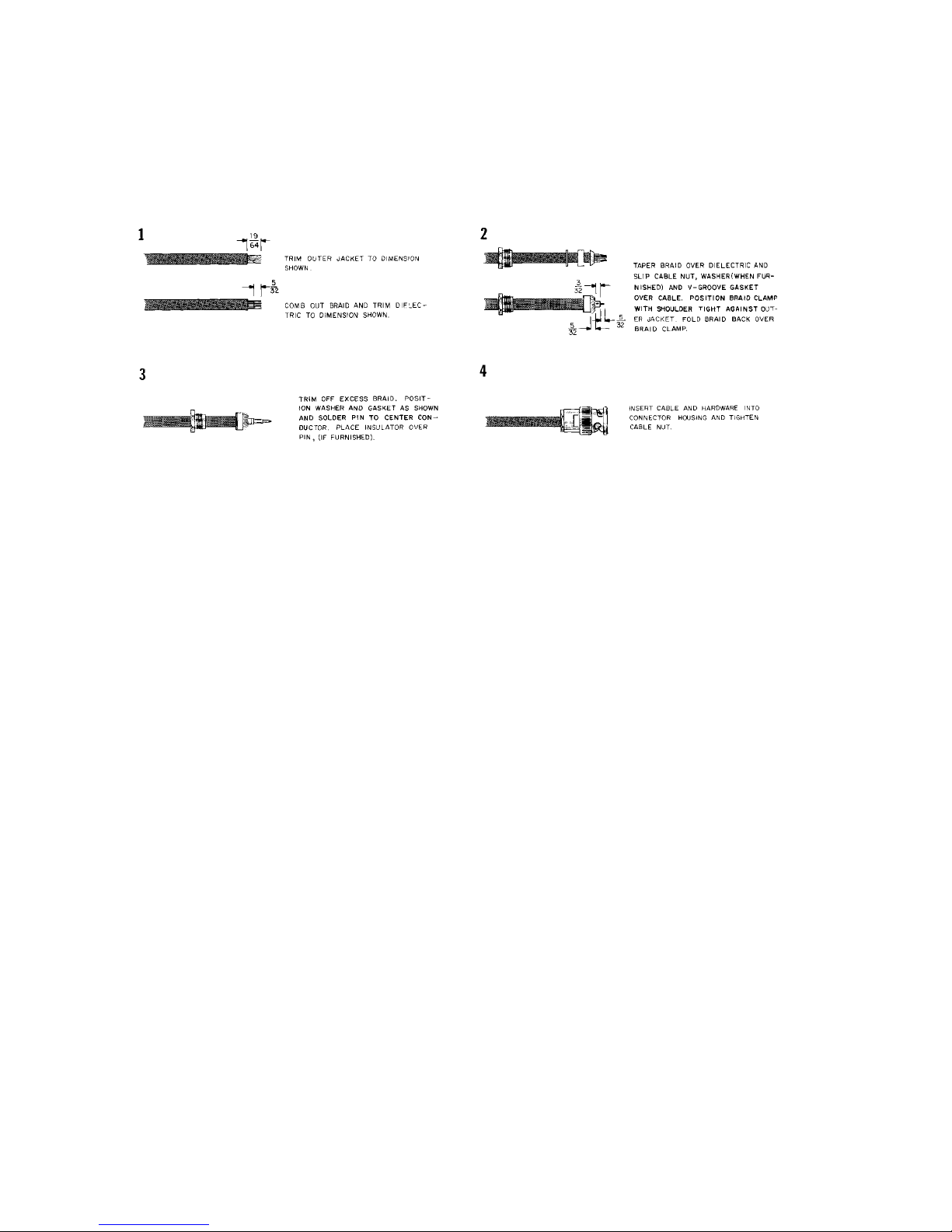
2-9 BNC CONNECTOR CABLE ASSEMBLY DRAWING . . . . . . . . . . . . . . . . . . . . . . . . . 2-28
3-1 UNIT FUNCTIONS. . . . . . . . . . . . . . . . . . . . . . . . . . . . . . . . . . . . . . . . . . . . . . . . . . . . . 3-1
3-2 STANDBY . . . . . . . . . . . . . . . . . . . . . . . . . . . . . . . . . . . . . . . . . . . . . . . . . . . . . . . . . . .3-2
3-3 TEST . . . . . . . . . . . . . . . . . . . . . . . . . . . . . . . . . . . . . . . . . . . . . . . . . . . . . . . . . . . . . . . 3-2
3-4 UNIT ON . . . . . . . . . . . . . . . . . . . . . . . . . . . . . . . . . . . . . . . . . . . . . . . . . . . . . . . . . . . . 3-3
3-5 ALTITUDE . . . . . . . . . . . . . . . . . . . . . . . . . . . . . . . . . . . . . . . . . . . . . . . . . . . . . . . . . . .3-3
3-6 IDENT . . . . . . . . . . . . . . . . . . . . . . . . . . . . . . . . . . . . . . . . . . . . . . . . . . . . . . . . . . . . . . 3-4
3-7 VFR . . . . . . . . . . . . . . . . . . . . . . . . . . . . . . . . . . . . . . . . . . . . . . . . . . . . . . . . . . . . . . . . 3-5
3-8 ALTITUDE DISPLAY . . . . . . . . . . . . . . . . . . . . . . . . . . . . . . . . . . . . . . . . . . . . . . . . . . . 3-6
LIST OF TABLES
Table Page
1-1 KT 76C TECHNICAL CHARACTERISTICS. . . . . . . . . . . . . . . . . . . . . . . . . . . . . . . . . . 1-2
1-2 KA 60 TECHNICAL CHARACTERISTICS. . . . . . . . . . . . . . . . . . . . . . . . . . . . . . . . . . . 1-6
1-3 KT 76C CONFIGURATIONS AVAILABLE . . . . . . . . . . . . . . . . . . . . . . . . . . . . . . . . . . . 1-6
1-4 KT 76C INSTALLATION KIT . . . . . . . . . . . . . . . . . . . . . . . . . . . . . . . . . . . . . . . . . . . . . 1-7
1-5 CABLE SETUP 4.5 to 11 FEET . . . . . . . . . . . . . . . . . . . . . . . . . . . . . . . . . . . . . . . . . . . 1-8
1-6 CABLE SETUP 10 to 25 FEET . . . . . . . . . . . . . . . . . . . . . . . . . . . . . . . . . . . . . . . . . . . 1-8
1-7 CABLE SETUP 16 to 32 FEET . . . . . . . . . . . . . . . . . . . . . . . . . . . . . . . . . . . . . . . . . . . 1-8
2-1 INSPECTION/CHECK PROCEDURE . . . . . . . . . . . . . . . . . . . . . . . . . . . . . . . . . . . . . 2-14
2-2 RAMP TESTS . . . . . . . . . . . . . . . . . . . . . . . . . . . . . . . . . . . . . . . . . . . . . . . . . . . . . . . 2-17
Rev 3, May 2004 IM 006-10545-0003.dwd TOC-2
Page 7

B ATCRBS TRANSPONDER KT 76C
SECTION I
GENERAL
1.1 INTRODUCTION
This manual contains information relative to the physical, mechanical, and electrical characteristics of the Honeywell Silver Crown KT 76C ATCRBS Transponder. Installation and operating
procedures are also included. Information relative to the maintenance, alignment, and procure-
ment of the replacement parts may be found in the KT 76C Maintenance/Overhaul Manual,
P/N 006-15545-00XX (XX = latest revision available).
1.2 EQUIPMENT DESCRIPTION
The KT 76C is a panel mounted, TSO certified Transponder designed to fulfill the role of the airborne beacon equipment according to the requirements of the Air Traffic Radar Beacon System
(ATCRBS) that include ATCRBS Mode A, and ATCRBS Mode C.
The KT 76C features a microprocessor controlled gas discharge display. The 4096 identification
code selection is entered with push-button switches. A rotary knob is used for mode selection control. Additional push-button switches including IDT, VFR, and CLR are provided.
When the KT 76C receives Mode A interrogations from the ground radar facility, it will transmit a
coded group of pulses which consist of a four digit identification number that has been assigned
by the Air Traffic Controller. This code is entered into the KT 76C by the pilot and is transmitted
back to the ground as a Mode “A” reply. This coded information is presented on the ground radar
display at the appropriate range and azimuth. The Air Traffic Controller can then identify each aircraft that is transponder equipped by its distinct coded number.
The VFR code and display brightness can be programmed from the front panel of the KT 76C and
stored in nonvolatile memory, this programming sequence is described in Section III.
The KT 76C also provides Mode “C” or altitude reporting information. When the KT 76C is operated in the “ALT” Mode and used in conjunction with an encoding altimeter, the flight level altitude
is displayed in addition to the transponder code, and the altitude information is transmitted to the
ground in response to Mode “C” interrogations.
When the “IDT” button is pressed, the current 4096 code and an additional special ident pulse are
transmitted by the KT 76C, to insure positive identification.
A test mode is also included in the KT 76C to confirm that all segments in the display are operational.
Rev 3, May 2004 IM 006-10545-0003.dwd Page 1-1
Page 8

B ATCRBS TRANSPONDER KT 76C
1.3 TECHNICAL CHARACTERISTICS
1.3.1 KT 76C PHYSICAL CHARACTERISTICS
Table 1-1 KT 76C Technical Characteristics
TSO Compliance: C74c Class 1A
Environmental - See TSO Appendix
Software - Criticality Level “D”
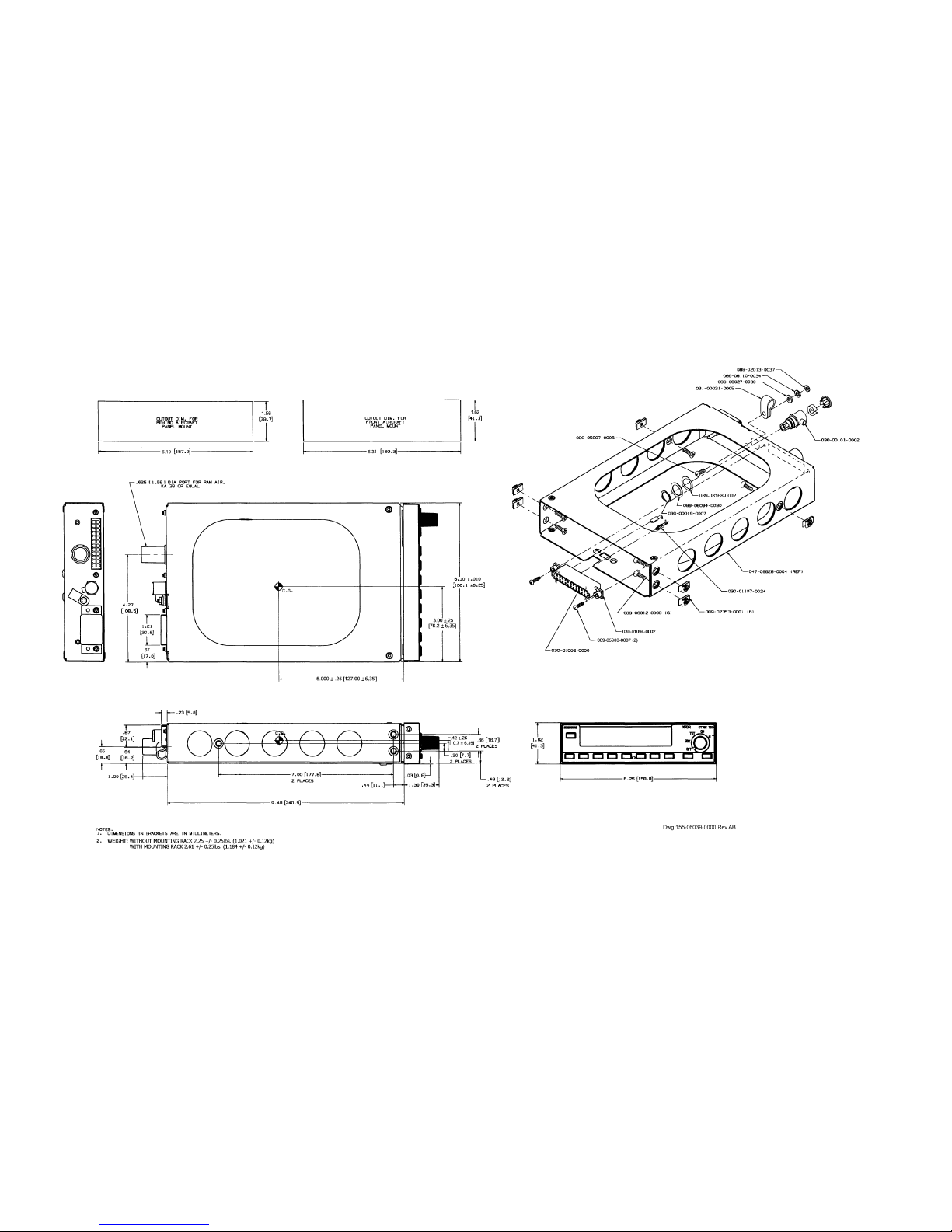
Physical Dimensions: See Figure 2-3, Dwg No. 155-06039-0000.
Weight: See Figure 2-3, Dwg No. 155-06039-0000.
Applicable Documents: TSO-C74c (Technical Standard Order ATC
Transponder Equipment)
RTCA DO-160C (Environmental Conditions and Test
Procedures)
RTCA DO-178B (Software Considerations in Airborne
Systems)
Mounting: Panel Mounted
Temperature: -20 °C to +55 °C
Altitude: 35,000 feet
Cooling: No forced air cooling required, but recommended.
Vibration: Constant total excursion of 0.2 in. from 5 to 17 Hz
From 17 to 38 Hz - 3.0 g-pk
From 38 to 500 Hz - 1.5 g-pk
From 500 to 2000 Hz - 1.0 g-pk
Shock: Rigid mounting 6 G operational 15 G crash safety.
Power Input: Watts maximum
0.7 Amperes @ 27.50 Vdc
1.6 Amperes @ 13.75 Vdc
Standby current:
0.400 A @ 28 Vdc
0.758 A @ 14 Vdc
Lighting current:
55 +/- 17 mA @ 28 Vdc
110 +/- 34 mA @ 14 Vdc
Receiver Characteristics:
Sensitivity Variation with Frequency: The RF input level required to produce 90% replies will
not vary by more than 1 dB between modes and will at
no time exceed a level of -69 dBm for standard
ATCRBS interrogations in the frequency range
between 1029.8 and 1030.2 MHz.
Bandwidth: A standard ATCRBS interrogation signal below 1005
Rev 3, May 2004 IM 006-10545-0003.dwd Page 1-2
MHz and above 1055 MHz will be at least 60 dB
stronger than that required to produce the same reply
efficiency at 1030 MHz.
Page 9

B ATCRBS TRANSPONDER KT 76C
Table 1-1 KT 76C Technical Characteristics
Sensitivity and Dynamic Range: The minimum triggering level (MTL) is defined as the
minimum input power level that results in a 90% reply
ratio if the interrogation has nominal pulse
characteristics.
A. The MTL for ATCRBS will be -73 dBm +/- 4 dB.
B. The reply ratio will be at least 90% for ATCRBS
interrogations between MTL and 50 dB above MTL.
C. The variation of MTL between ATCRBS Mode A
and Mode C interrogations will not exceed 1 dB.
Transmitter Characteristics:
Reply Transmission Frequency: The transmitter frequency of the reply will be 1090+/-
3MHz when observed in a 50Ω load with a VSWR of
1.2:1 or less.
RF Peak Power Output: The transmitter output power will be 125 watts peak
power minimum and 500 watts peak power maximum
at the terminals of the transponder antenna. The pulse
amplitude variation between any two pulses in an
ATCRBS reply will not exceed 1 dB.
ATCRBS Reply Rate Capability: The transponder will be able to continuously generate
at least 500 ATCRBS 15-pulse replies per second and
will have the capability of a peak reply rate of 1,200
ATCRBS 15-pulse replies.
NOTE: A 15-pulse reply includes 2 framing pulses, the
12 information pulses, and the SPI pulse.
Reply Pulse Characteristics:
ATCRBS Reply Pulse Positions The reply function will consist of two framing pulses
and 13 information pulses. The pulse spacing
tolerance for each pulse (including the last framing
pulse) with respect to the first framing pulse of the
reply group will be +/- 0.10 µsec. The pulse spacing
tolerance of any pulse in the reply group with respect
to any other pulse (except the first framing pulse) will
be no more than +/- 0.15 µsec.
Rev 3, May 2004 IM 006-10545-0003.dwd Page 1-3
Page 10

B ATCRBS TRANSPONDER KT 76C
Table 1-1 KT 76C Technical Characteristics
ATCRBS Reply Pulse position from the
first framing pulse are as follows:
ATCRBS SPI Reply Pulse: Upon activation of the IDENT switch, the SPI pulse will
PULSE POSITION (µsec)
F1 ........... ........... 0.00 (Reference)
C1 ........... ........... 1.45
A1 ........... ........... 2.90
C2 ........... ........... 4.35
A2 ........... ........... 5.8
C4 ........... ........... 7.25
A4 ........... ........... 8.70
B1 ........... ........... 11.60
D1 ........... ........... 13.05
B2 ........... ........... 14.50
D2 ........... ........... 15.95
B4 ........... ........... 17.40
D4 ........... ........... 18.85
F2 ........... ........... 20.30
SPI........... ........... 24.65
be transmitted when replying to ATCRBS Mode A
interrogations for a period of 18 +/- 2 seconds. The
pulse spacing tolerance of the SPI pulse with respect
to the last framing pulse will be +/- 0.10 µsec. The SPI
pulse will not be transmitted when replying to Mode C
interrogations.
ATCRBS Reply Pulse Shape: All reply pulses and SPI pulses will be 0.45 µsec +/-
0.10 µsec duration and have rise times of 0.05 µsec
through 0.1 µsec and decay times of 0.05 µsec
through 0.2 µsec.
ATCRBS Reply Delay and Jitter: A. At all RF input levels from MTL to 50 dB above
MTL, the time delay from the leading edge of P3 to the
leading edge of F1 (the first pulse of the reply) will be
3.0 +/- 0.5 µsec.
B. At all RF levels from MTL + 3 to 50 dB above MTL
the time delay variations between ATCRBS modes will
not exceed 0.2 µsec.
C. At all RF input levels from MTL + 3 dB to 50 dB
above MTL the jitter at the leading edge of the first
pulse of the reply with respect to P3 will not exceed +/
- 0.10 µsec.
Suppression I/O This pin is both an input and an output. The
transponder will be suppressed if the input is +18 V dc
to +70 V dc. While the transponder is transmitting it
will drive this pin above 18 V dc. As an output, 18 volts
will be maintained into a load of 300 ohms and 1850
pF.
Suppression In The transponder will be suppressed if the voltage
Rev 3, May 2004 IM 006-10545-0003.dwd Page 1-4
applied to this pin is above 6 V dc. This pin follows an
Honeywell standard.
Page 11

B ATCRBS TRANSPONDER KT 76C
Table 1-1 KT 76C Technical Characteristics
Side Lobe Suppression Characteristics:
SLS Decoding and Dynamic Range: A. When the RF input signal is varied from MTL +3 dB
to 50 dB above MTL and the level of P2 equals or
exceeds the level of P1 spaced 2.0 +/- 0.15 µsec from
P1 the transponder will reply to no more than 1% of the
interrogations.
B. When the RF input signal is varied from MTL +3 dB
to 50 dB above MTL and the level of P1 exceeds the
level of P2 by 9 dB or more, or P2 =P1 and is spaced
1.3 µsec or 2.7 µsec from P1, the transponder will
reply to at least 90% of the interrogations.
Pulse Decoder Characteristics: Unless otherwise specified, the following pulse
decoder characteristics will apply for an RF input
signal levels of MTL to 50 dB above MTL and nominal
interrogation signal characteristics. Applicable “valid”
interrogations will result in at least 90% replies, and
interrogations which are “invalid” will result in less than
10% replies.
Pulse Position Tolerances: A. The transponder will accept the pulse position of
ATCRBS interrogations as valid if the spacing
between P1 and P3 is within +/- 0.2 µsec of the
nominal spacing.
B. The transponder will not accept the pulse position
of ATCRBS as valid if the spacing between P1 and P3
differs from the nominal spacing by 1.0 µsec or more.
Pulse Duration Tolerances: The transponder will accept the pulses of an ATCRBS
interrogation as valid if the duration of both P1 and P3
is between 0.7 and 0.9 µsec.
NOTE: All measurements are made with a 2 dB cable loss.
Rev 3, May 2004 IM 006-10545-0003.dwd Page 1-5
Page 12

B ATCRBS TRANSPONDER KT 76C
1.3.2 KA 60 PHYSICAL CHARACTERISTICS
Table 1-2 KA 60 Technical Characteristics
TSO Compliance: TSO C66a (DME)
TSO C74c (Transponder)
DO-160 Environmental Categories:
D2A/JY/XXXXXXXXXXX
Physical Dimensions: Height: 3.13 ± 0.2 inches (79.502 ± 5.08 mm)
Width: 0.95 ± 0.2 inches (24.13 ± 5.08 mm)
Length: 4.05 ± 0.2 inches (102.87 ±5.08 mm)
Weight: 0.20 lbs (0.09 kg)
Temperature: -55 °C to +71 °C
Altitude: 55,000 feet
Vibration: 0.2 inch/ 2g - 0.02 inch /5g
Shock: Rigid mounting 6 G operational 15 G crash safety.
1.4 UNITS AND ACCESSORIES SUPPLIED
1.4.1 CONFIGURATIONS AVAILABLE
Table 1-3 lists the available configurations of the transponder and the features contained in each
configuration.
Table 1-3 KT 76C Configurations Available
HONEYWELL
PART NUMBER
066-01156-0101 11 - 33 Vdc 14 or 28 Vdc 047-09628-0004 200-09478-0010
066-01156-0201 11 - 33 Vdc 14 or 28 Vdc 047-09628-0004 200-09478-0020
SUPPLY
VOLTAGE
LAMP
VOLTAGE
MOUNTING
RACK
CIRCULATOR
BOARD
Rev 3, May 2004 IM 006-10545-0003.dwd Page 1-6
Page 13

B ATCRBS TRANSPONDER KT 76C
1.4.2 KT 76C INSTALLATION KIT
The KT 76C Transponder installation kit contains the following parts:
Table 1-4 KT 76C Installation Kit P/N 050-01577-0001, Rev 14
PART NUMBER DESCRIPTION UM QTY VENDOR NAME & PART
NUMBER
006-01058-0005 RF CONN ASSY INST EA 1
030-00005-0000 CONN BNC CA RG142 EA 1 Ted Manufacturing 4-10-4
030-00101-0002 PANEL MOUNT PLUG EA 1 Ted Manufacturing 9-30-10
030-01094-0002 CONNECTOR 12/24 P EA 1
030-01096-0000 KEY POLARIZER EA 1
030-01107-0024 CONNECTOR TERM 24T EA 1
089-02013-0037 NUT HEX 6-32 EA 1
089-02353-0001 NUT CLIP 6-32 EA 6
089-05903-0007 SCR PHP 4-40 X 7/16 EA 2
089-05907-0006 SCR PHP 6-32 X 3/8 EA 1
089-06012-0008 SCR PHP 6-32 X 1/2 EA 6
089 08027-0030 WSHR FLT STD #6 EA 1
089-08094-0030 WSHR FLT STD .446 EA 1
089-08110-0034 WSHR SPLT LK #6 EA 1
Honeywell
Honeywell
Honeywell
Honeywell
Honeywell
Honeywell
Honeywell
Honeywell
Honeywell
Honeywell
Honeywell
Honeywell
089-08168-0002 WASHER WAVE EA 1
090-00019-0007 RING RTNR .438 EA 1
091-00031-0005 NY CA CLAMP .312 EA 1 Richco N-5
Rev 3, May 2004 IM 006-10545-0003.dwd Page 1-7
Honeywell
Honeywell
Page 14

B ATCRBS TRANSPONDER KT 76C
1.5 ACCESSORIES REQUIRED, BUT NOT SUPPLIED
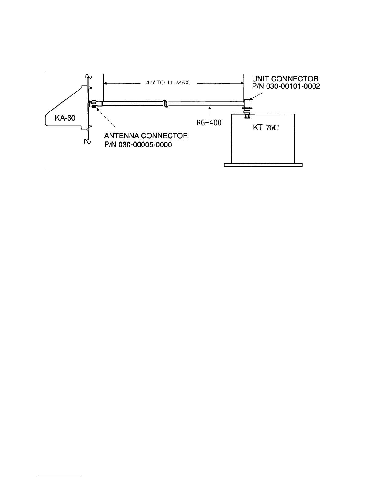
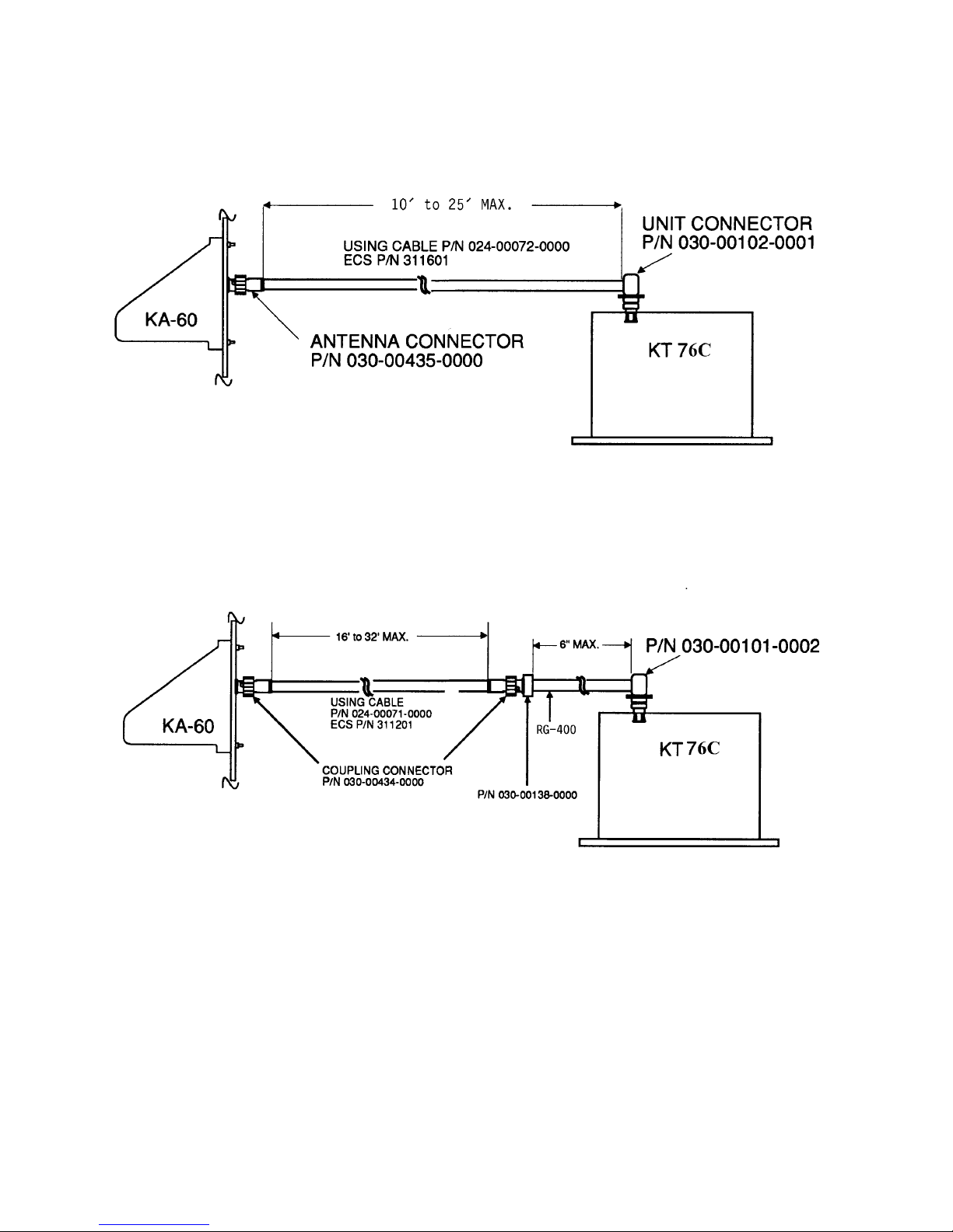
The following parts are recommended for a cable setup with dimensions of 4.5 feet to 11 feet: (See
Figure 2-5, Sheet 1 of 2).
Table 1-5 Cable Setup 4.5 to 11 Feet
HONEYWELL PART NUMBER DESCRIPTION QUANTITY
006-01058-0005 Connector Assy Procedure 1
024-00051-0060 Cable, Coax 11 ft.
030-00092-0000 Connector, Coax Mod Type BNC 1
030-00101-0002 Connector, Coax 1
The following parts are recommended for a cable setup with dimensions of 10 feet to 25 feet: (See
Figure 2-5, Sheet 2 of 2).
Table 1-6 Cable Setup 10 to 25 Feet
HONEYWELL PART NUMBER DESCRIPTION QUANTITY
006-01058-0005 Connector Assy Procedure 1
024-00072-0000 Cable, Coax 25 ft.
030-00102-0001 Connector, Type Unit 1
030-00435-0000 Connector, Antenna 1
The following parts are recommended for a cable setup with dimensions of 16 feet to 32 feet:
(SeeFigure 2-5, Sheet 2 of 2).
Table 1-7 Cable Setup 16 to 32 Feet
HONEYWELL PART NUMBER DESCRIPTION QUANTITY
006-01058-0005 Connector Assy Procedure 1
024-00051-0060 Cable, Coax 6 in.
024-00071-0000 Cable, Coax 32.5 ft.
030-00101-0002 Connector Type Unit 1
030-00138-0000 Cable, Unit extension to antenna
030-00434-0000 Connector, Antenna 2
Rev 3, May 2004 IM 006-10545-0003.dwd Page 1-8
1
connector
Page 15

B ATCRBS TRANSPONDER KT 76C
1.6 LICENSE REQUIREMENTS
The transmitter, as installed in the aircraft, requires an Aircraft Radio Station License. This license
is obtained by filing the FCC Form 404. While awaiting the receipt of the station license, a copy
of FCC Form 404 is kept in the aircraft.
This equipment has been type accepted by the FCC and entered on the type accepted equipment
list, as Honeywell KT 76C and must be identified as Honeywell KT 76C on your Form 404, Aircraft
Radio Station License application.
1.7 INSTRUCTIONS FOR CONTINUED AIRWORTHINESS
The instructions for continued airworthiness given in the TC or STC approvals for this product supplements or supersedes the instructions for continued airworthiness in this manual.
Most Honeywell products are designed and manufactured to allow "on condition maintenance".
On condition maintenance is described as follows; There are no periodic service requirements
necessary to maintain continued airworthiness. No maintenance is required until the equipment
does not properly perform its intended function. When service is required, a complete performance test should be accomplished following any repair action. Consult the appropriate unit
Maintenance/Overhaul Manual for complete performance test information.
Rev 3, May 2004 IM 006-10545-0003.dwd Page 1-9
Page 16

B ATCRBS TRANSPONDER KT 76C
THIS PAGE RESERVED BLANK
Rev 3, May 2004 IM 006-10545-0003.dwd Page 1-10
Page 17

B ATCRBS TRANSPONDER KT 76C
SECTION II
INSTALLATION
2.1 GENERAL INFORMATION
This section contains suggestions and factors to consider before installing the KT 76C ATCRBS
Transponder. Close adherence to these suggestions will assure a more satisfactory performance
from the equipment.
The conditions and tests required for TSO approval of this article are minimum performance standards. It is the responsibility of those desiring to install this article either on or within a specific
type or class of aircraft to determine that the aircraft installation conditions are within TSO standards. The article may be installed only if further evaluation by the applicant documents an acceptable installation and is approved by the Administrator.
2.2 UNPACKING AND INSPECTING EQUIPMENT
Exercise extreme caution when unpacking the unit. Make a visual inspection of the unit for evidence of damage incurred during shipment. If a claim for damage is to be made, save the shipping
container to substantiate the claim. Save all packing materials for use in unit storage or reshipment.
2.3 EQUIPMENT INSTALLATION
2.3.1 GENERAL
The following paragraphs contain information pertaining to the initial installation of the KT 76C ATCRBS Transponder, including instructions concerning the location and mounting of the supporting
antenna.
The equipment should be installed in the aircraft in a manner consistent with acceptable workmanship and engineering practices and in accordance with the instructions set forth in this publication.
To ensure that the system has been properly and safely installed in the aircraft, the installer should
make a thorough visual inspection and conduct an overall operational check of the system on the
ground prior to flight.
CAUTION
AFTER INSTALLATION OF THE CABLING AND
BEFORE INSTALLATION OF THE EQUIPMENT, A
CHECK SHOULD BE MADE WITH THE AIRCRAFT
PRIMARY POWER SUPPLIED TO THE MOUNTING CONNECTOR TO ENSURE THAT POWER IS
APPLIED ONLY TO THE PINS SPECIFIED IN THE
INTERCONNECT DIAGRAM,
The KT 76C system installation will conform to standards designated by the customer, installing
agency and existing conditions as to the unit location and type of installation. However, the following suggestions should be considered before installing your KT 76C system.
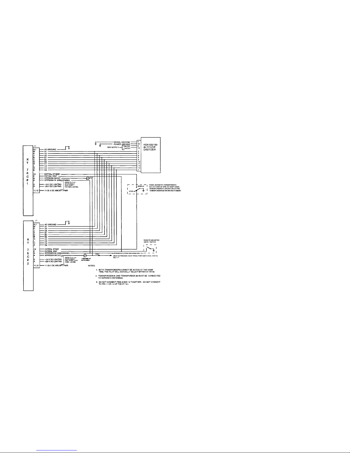
FIGURE 2-2.
2.3.2 AVIONICS COOLING REQUIREMENTS FOR PANEL MOUNTED EQUIPMENT
The greatest single contributor to increased reliability of all modern day avionics is to limit the maximum operating temperature of the individual units whether panel or remote mounted. While modern day individual circuit designs consume much less electrical energy, the watts per cubic inch
Rev 3, May 2004 IM 006-10545-0003.dwd Page 2-1
Page 18

B ATCRBS TRANSPONDER KT 76C
dissipated within avionics units remains much the same because of the high density packaging
techniques utilized. Consequently, the importance of providing avionics stack cooling is essential
to the life span of the equipment.
While each individual unit may not require forced air cooling, the combined heat load of several
units operating in a typical avionics stack will significantly degrade the reliability of the avionics if
provisions for stack cooling are not incorporated in the initial installation. Recommendations on
stack cooling are contained in Honeywell Installation Bulletin #55. Failure to provide stack cooling
will certainly lead to increased avionics maintenance costs and may void the warranty.
2.3.3 KT 76C INTERCONNECT WIRING AND CABLE HARNESS FABRICATION
A. General
The KT 76C ATCRBS Transponder receives primary power from the aircraft
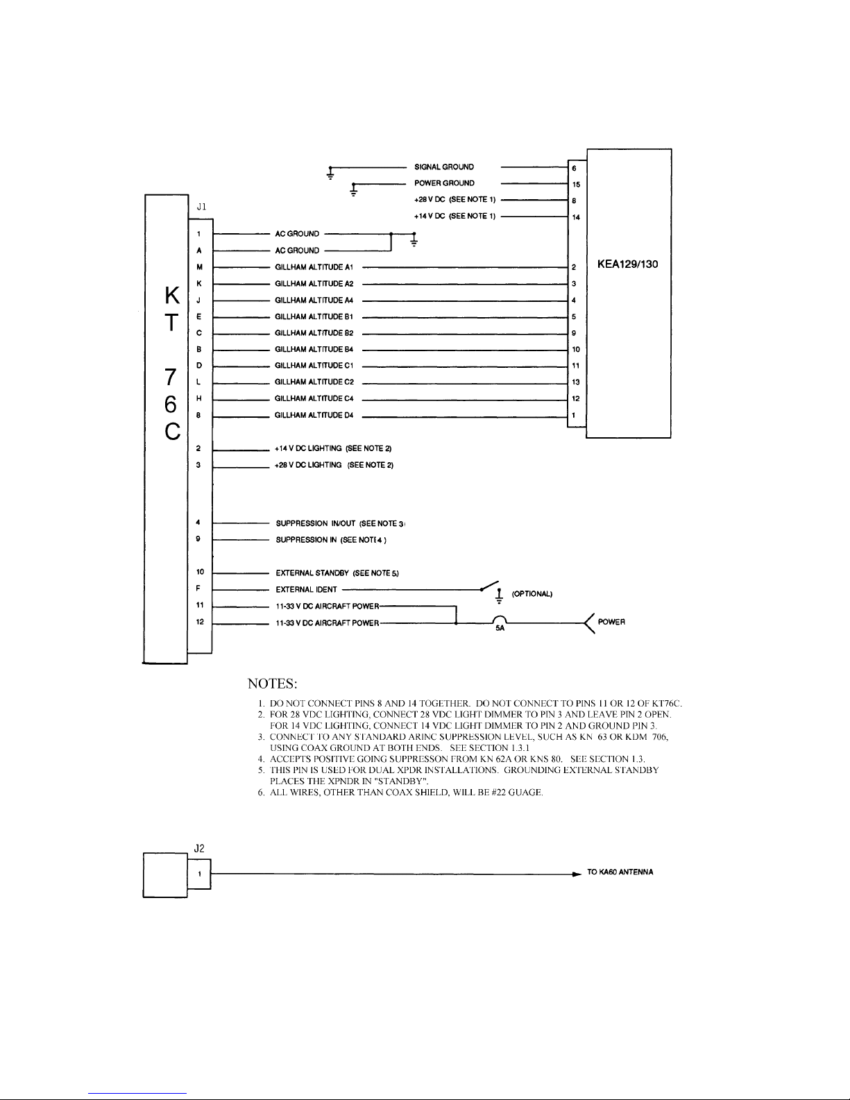
power source. Power connections, voltage requirements, circuit breaker requirements are shown on the interconnect diagram (see Figure 2-2).
The length of the wires to parallel pins should be approximately the same
length, so that the best distribution of current can be effected. Honeywell recommends that all wires, including spares as shown on the interconnect diagram be included in the fabrication of the wiring harness. However, if full wiring is not desired, the installer should ensure that the minimum wiring requirements for the features and functions to be used be incorporated.
When cables are installed in the aircraft, they must be supported firmly
enough to prevent movement and should be carefully protected against chaffing. Additional protection should also be provided in all location where the cable may be subjected to abuse.
In wire bundles, the cabling should not be tied tightly together as this tends to
increase the possibility of noise pickup and similar interference. When routing
cables through the aircraft the cables should cross high level rf lines at right
angles.
The following guidelines are recommended:
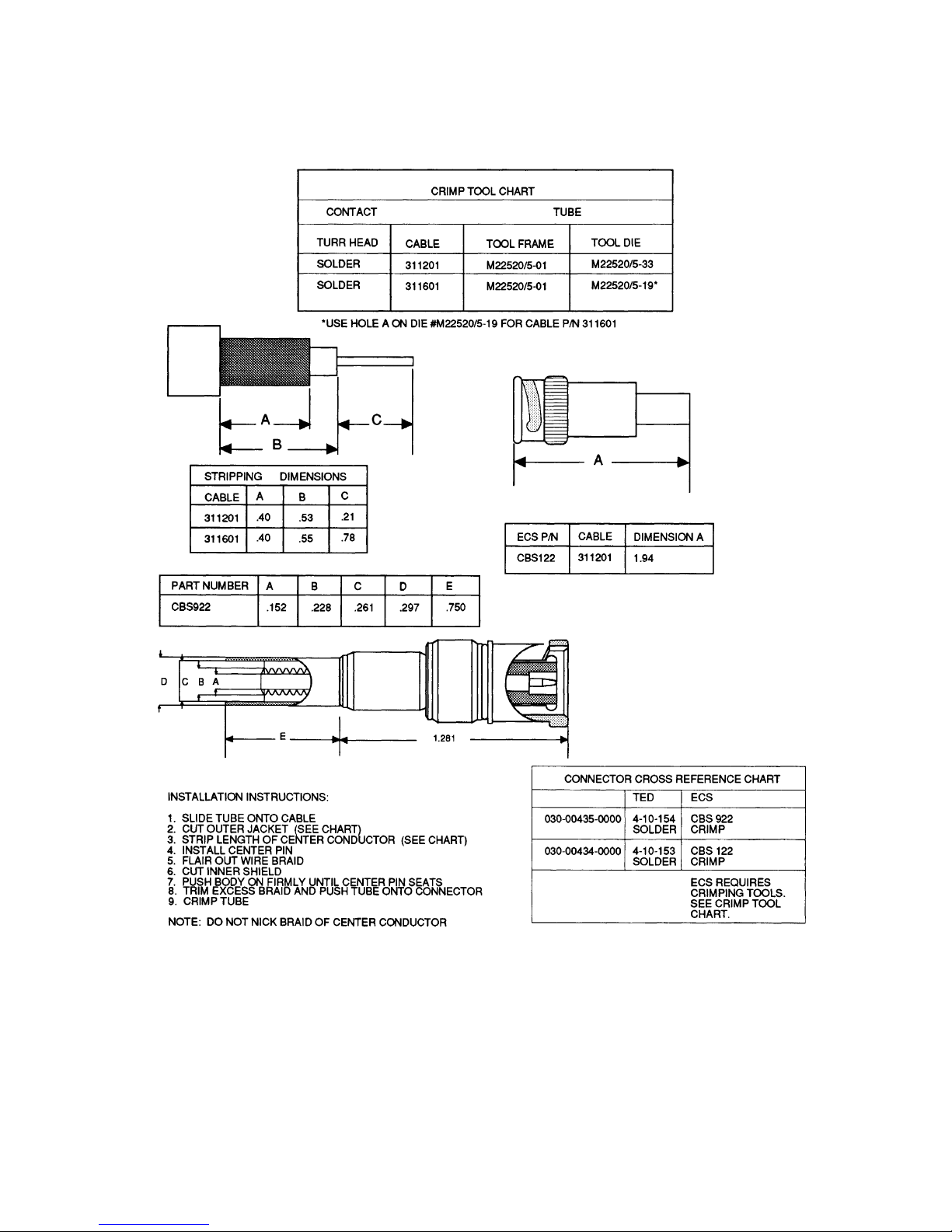
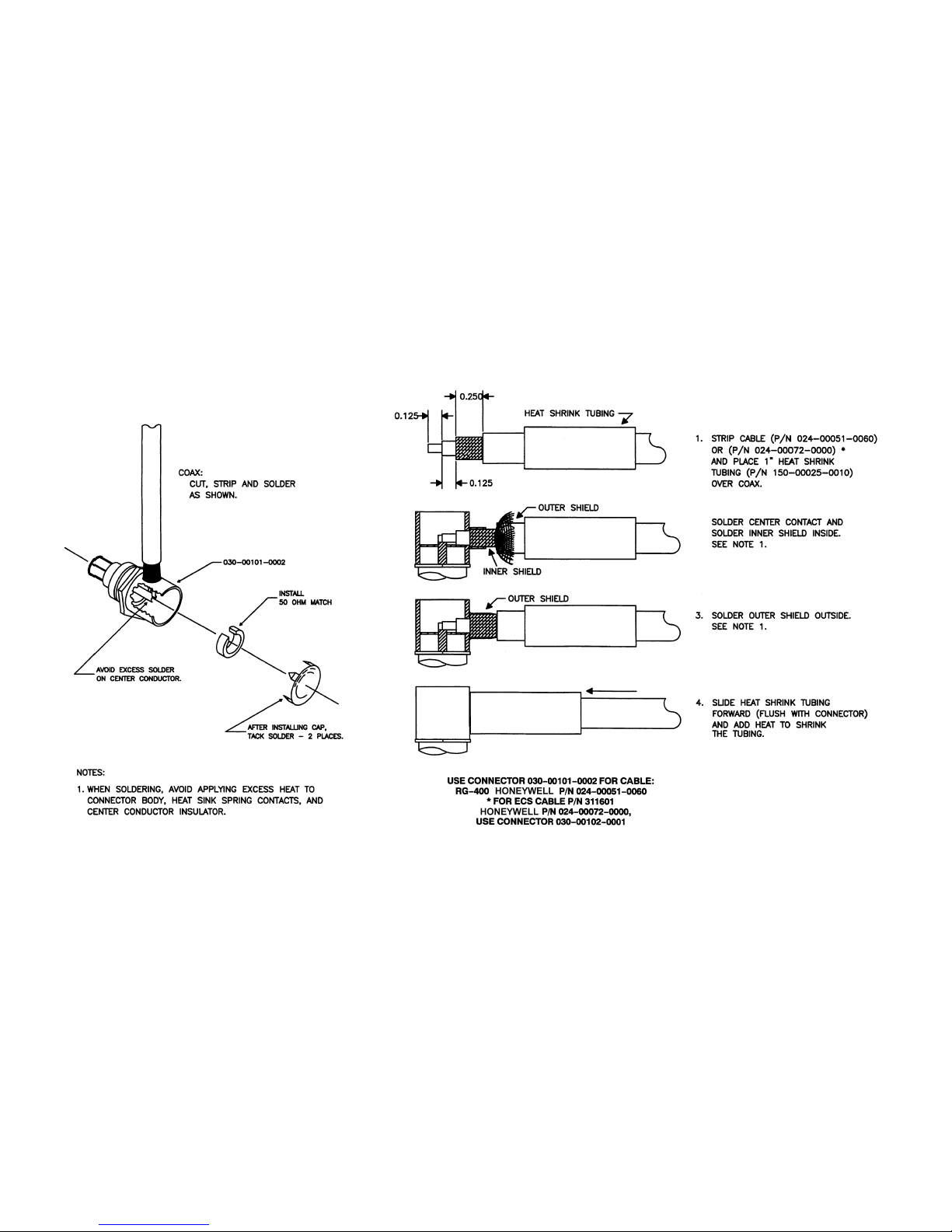
(1) The installing facility will supply and fabricate all external cables. (See
Figures 2-5 through Figure 2-9). The required connectors are supplied
as part of the installation kit (P/N
(2) The KT 76C and the associated wiring harness must be kept a minimum
of three feet from the transponder antenna coax and the termination connector of the antenna to prevent rf interference from the antenna.
(3) Do not route the transponder antenna coax near ADF sense or loop an-
tenna cables.
The total losses in the coaxial cable run and interconnects between the omni antenna and the KT 76C
transponder must be less than or equal to (
Use Figure 2-2 as a reference and adhere to the dimensions prescribed in Figure 2-5.
050-01577-0001).
NOTE
≤)2 dB.
Rev 3, May 2004 IM 006-10545-0003.dwd Page 2-2
Page 19

B ATCRBS TRANSPONDER KT 76C
B. Primary Power and Circuit Breaker Requirements and Wiring
The KT 76C transponder receives primary power from an aircraft by aircraft
power circuit breakers. The KT 76C is designed to operate from 11-33 V dc.
Power connections, wire sizes, and circuit breaker requirements are shown
on the interconnection diagram Figure 2-2.
2.3.4 EQUIPMENT LOCATION
Care should be exercised to avoid mounting components near equipment operating with high
pulse current or high power outputs such as radar and satellite communications equipment. In
general, the equipment should be installed in a location convenient for operation, inspection, and
maintenance, and in an area free from excessive vibration, heat, and noise generating sources.
All mechanical installation drawings, connector assembly diagrams, interconnect diagrams, and
connector pin assignment tables referenced in this section are located at the end of this section
of the manual. Determine the mounting location for system components following the guidelines
below.
Prior to installing any equipment, make a continuity check of all wires and cables associated with
the system. Then apply power and check for proper voltages at system connectors, and then remove power before completing the installation.
A. Transponder And Mounting Tray Locations
The tray-mounted KT 76C ATCRBS Transponder can be installed in any convenient location on the panel that is free from excessive heat and vibration
and which provides reasonable access for inspection and maintenance. To
achieve maximum performance, the KT 76C should be installed adjacent to
other receivers with similar functions.
To allow for inspection or repair of the wiring of the connector assembly itself,
sufficient lead length should be left so that when the mounting hardware for
the rear connectors and antenna coaxial cable is removed the assembly may
be pulled forward several inches. Also, a bend should be made in the harness
(at the rear connectors) to allow water droplets that might form on the harness
due to condensation, to drip off at the bend and not collect in the connection.
Except for antenna cables, (see Figure 2-5) the length of cables from the
KT 76C transponder mounting tray connector to other system units is not critical because unit interfaces are designed with high impedance inputs, low impedance outputs, and low noise susceptibility characteristics.
Forced air cooling is recommended but is not a requirement. Outline drawing
Figure 2-3 shows transponder and mounting tray dimensions.
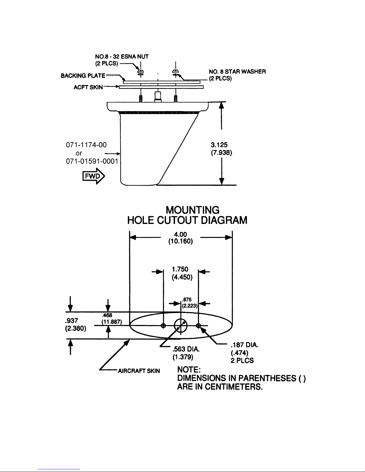
B. Antenna (see Figure 2-4)
The KT 76C antenna should be well removed from other antenna projections,
the engine(s), and propeller(s). It should also be well removed from landing
gear doors, access doors, or other openings which will break the ground
plane for the antenna as a surface directly beneath the antenna should be a
flat plane over as large area as possible.
A back-plate should be used for added strength on thin-skinned aircraft.
Rev 3, May 2004 IM 006-10545-0003.dwd Page 2-3
Page 20

B ATCRBS TRANSPONDER KT 76C
To prevent rf interference, the antenna must be physically mounted a minimum distance of three feet from the KT 76C and the wiring harness.
The transponder antenna should be mounted a minimum of six feet away
from the DME antenna, four feet from the ADF sense antenna, and three feet
from TCAS antennas.
Where practical, plan the antenna location to keep cable lengths as short as
possible and avoid sharp bends in the cable to minimize the VSWR.
Avoid running other cables or wires near the antenna cable.
On pressurized aircraft, the antenna should be sealed using RTV No. 3145
(P/N016-01082-0000) or equivalent around the connector and mounting
hardware.
All antenna mounts should be sealed around from the outside for moisture
protection using RTV or equivalent.
Mount the antenna in as clean as environment as possible, away from exhaust gases and oils. The antenna should be kept clean. If left dirty (oil covered), the range of the transponder may be affected.
2.3.5 KT 76C INSTALLATION
The mounting tray for the transponder should be mounted using the dimensions specified in the
outline and mounting drawing, Figure 2-3. The mounting tray should be wired according to the
system interconnect diagram, Figure 2-2.
A. Transponder Tray
(1) Rear connector wiring must be completed before permanently fastening
the mounting tray to the panel.
(2) Remove the area specified on the outline and mounting drawing (see
Figure 2-3) for front and rear dimensions. Care must be taken to avoid
damage to the adjacent equipment and cables.
(3) Secure the tray to the panel. The mounting tray must be secured in the
rear by attaching the tray to a structural member of the airframe.
(4) Look at the bottom of the unit and confirm the front lobe of the hold-down
device is in a vertical position. This can be accomplished by using a 3-32
inch Allen wrench through the front plate.
B. Transponder
(1) Slide the transponder into the tray until the front lobe touches the mount-
ing tray.
(2) Turn the Allen wrench clockwise until the rear lobe engages the mount-
ing tray slot. Continue turning the wrench clockwise until tight.
DO NOT OVERTIGHTEN THE LOCKING FASTENER
Rev 3, May 2004 IM 006-10545-0003.dwd Page 2-4
CAUTION
Page 21

B ATCRBS TRANSPONDER KT 76C
C. Antenna
(1) General
For L-band blade antenna outline drawing, installation procedures, and
mounting dimensions, refer to the manufacture’s instructions.
(2) KA 60
(a) Peel backing off the antenna template and apply the template to the
aircraft at the desired mounting location.
(b) Drill or cut the proper size holes for mounting the antenna, then re-
move the template.
(c) Using the antenna as a stencil, draw a line around the base of the
antenna where it comes into contact with the aircraft. Then carefully scrape off the paint within the stenciled area. Lightly sand the
bare metal with fine sandpaper to insure the removal of all paint
and protective coatings.
(d) Sand the inside area of the aircraft where the backing plate will be
located to remove chromate or other protective finish.
(e) Apply Alumiprep No.33, or equivalent, following the manufacturer’s
directions to cleanse the metal of any residue.
(f) Apply Alodine no. 1001, or equivalent, following the directions on
the container.
(g) Align the backing plate with the holes drilled in step (b). Fasten the
backing plate securely in place, if required for reinforcement.
(h) Mount the antenna using #8 star washer and 8-32 fasteners includ-
ed with the antenna.
(i) Coaxial cable RG400, or equivalent, is normally used on installa-
tions having a cable run of eleven feet or less. For cable runs from
ten to 32.5 feet, use low loss antenna parts, refer to Section 1 paragraph 1.4.2 or 1.5.
(j) Inspect coaxial cable connector for proper contact, then fasten the
connector securely to the antenna.
D. Programming Options
The VFR code and display brightness can be programmed and their values
stored in EEPROM. To program the VFR code or display brightness parameters please refer to Sections 3.2.2.C. or 3.2.2.F.(1), respectively.
2.3.6 VOLTAGE CHANGEOVER INSTRUCTIONS
The KT 76C is designed to operate with an input voltage of 11-33 V dc. The panel lamps are internally wired to operate from either a 14 V dc, or 28 V dc panel lighting system, depending on the
connections at the rear connector. Details of this panel lighting option are shown on the interconnect drawing Figure 2-2. No internal wiring changes are required.
2.3.7 KT 76A/KT 78A TO KT 76C - CHANGEOVER INSTRUCTIONS
If the KT 76C will be installed in place of an existing KT 76A/78A installation follow the procedures
below.
Rev 3, May 2004 IM 006-10545-0003.dwd Page 2-5
Page 22

B ATCRBS TRANSPONDER KT 76C
A. Power Requirements
(1) Voltage Change Kit Removal
On 28 V dc installations a voltage changeover kit (P/N 050-01578-0000)
was installed. The 10-Ω, 55-W, resistor, (132-00113-0004) must be removed from pin 11 in the wiring harness.
(2) Additional Supply Line (Recommended but not required)
Add pin 12 to support the additional current (see Figure 2-2, sheet 1, for
details).
(3) Change the harness fuse from 3 A to 5 A current rating.
(4) The RFI Suppression Adaptor (P/N 071-02010-0000) must be removed
if it was installed.
B. Additional Features
The following pin may be added to obtain the additional feature:
Pin 4 Suppression Line In/ Out
2.3.8 MOLEX CONNECTOR ASSEMBLY PROCEDURE
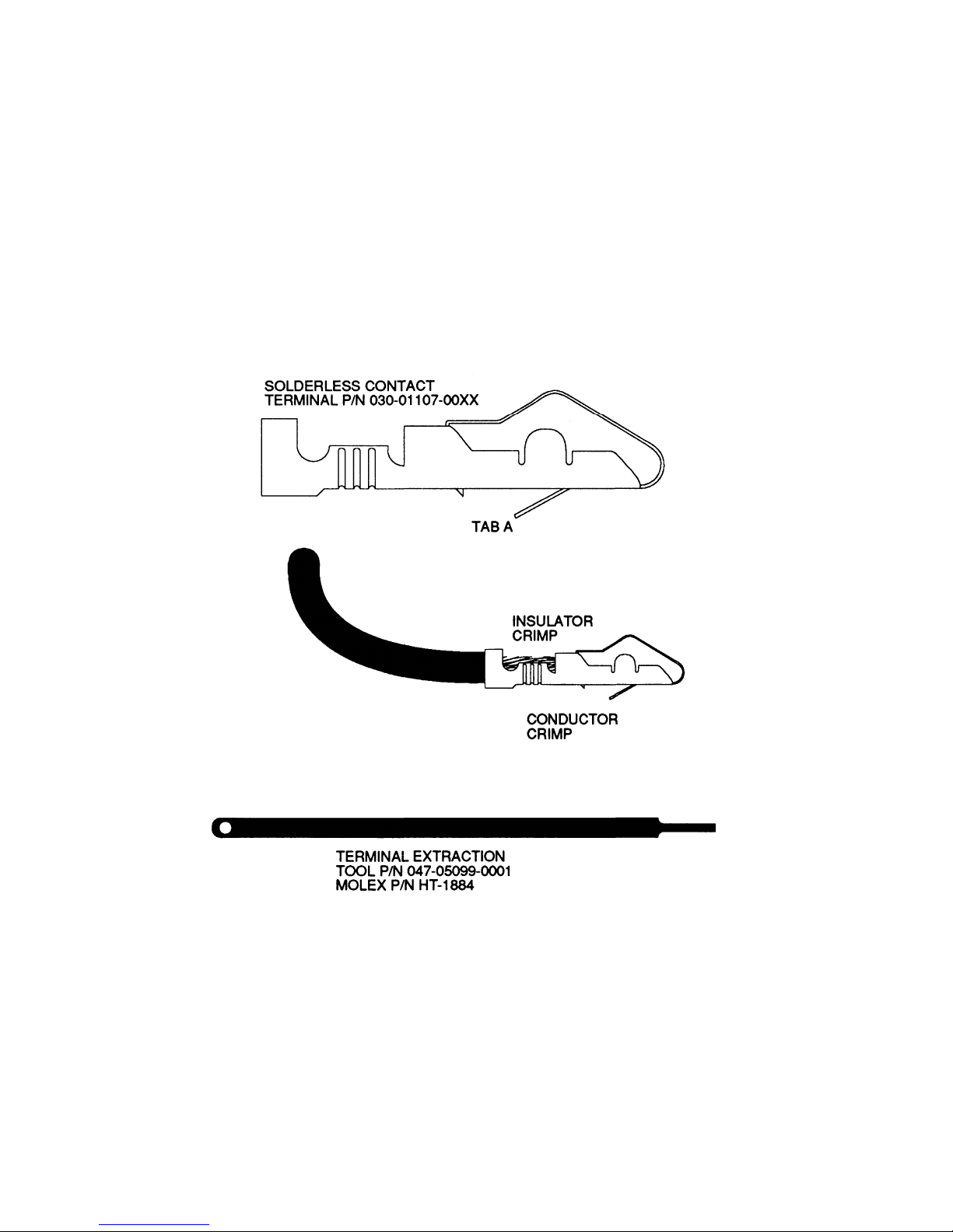
The KT 76C uses a special connector that mates directly with the printed circuit board inside the
unit (see Figure 2-1). Assemble the connector using the following procedure:
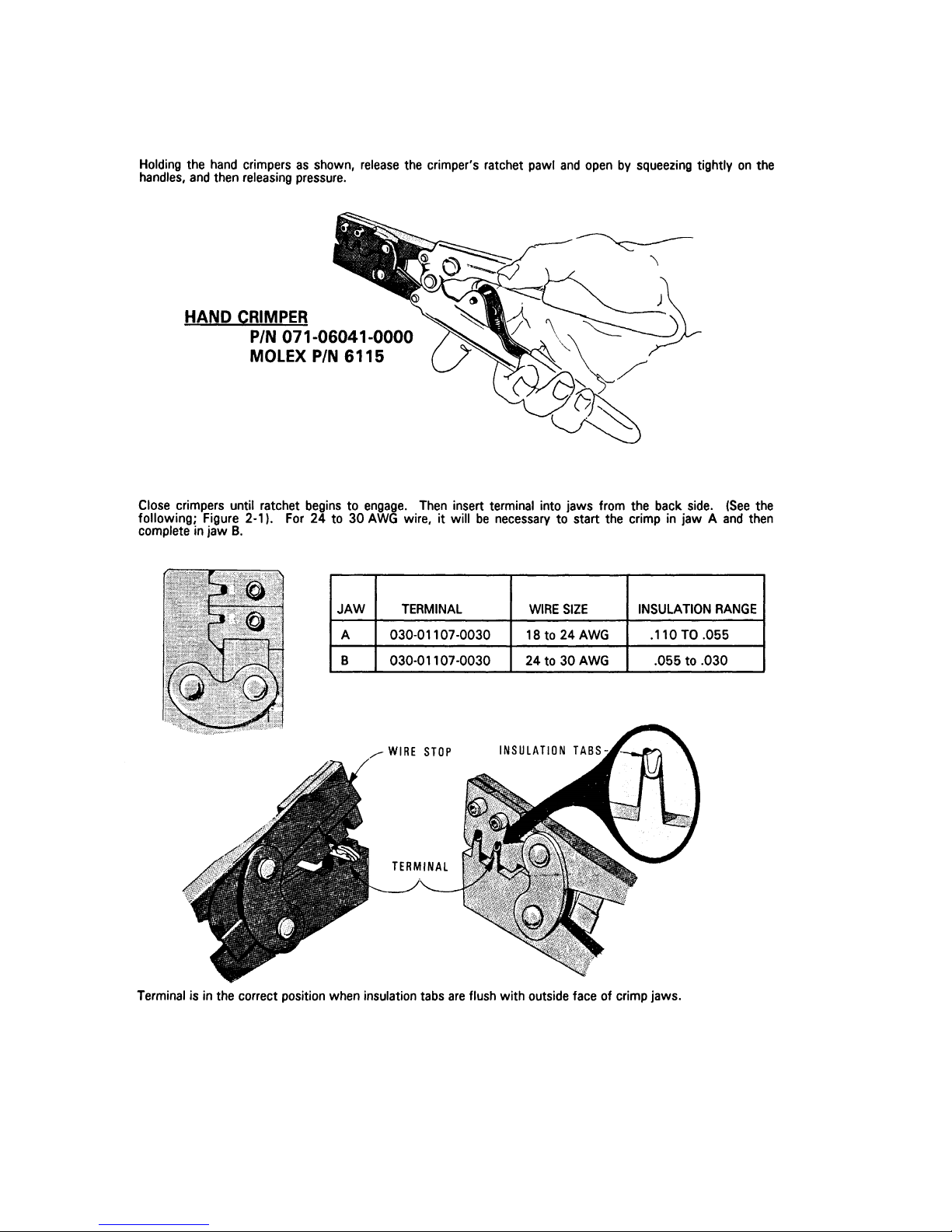
A. Solderless Contact Terminal Assembly using Molex Crimper
Refer to instructions in Figure 2-1.
B. Solderless Contact Terminal Assembly using Pliers
(1) Strip each wire 5/32 inches for contact terminal (P/N 030-01107-0024).
The last two digits of the contact terminal part number indicates the num-
ber of terminals furnished.
(2) Tin the exposed conductor.
(3) Using needle nosed pliers, fold over each conductor tab, in turn, onto the
exposed conductor. When both tabs have been folded, firmly press the
tabs against the conductor.
(4) Repeat step (3) for insulator tabs.
(5) Apply a small amount of solder (using minimum heat) to the conductor/
tab connection to assure a good electro-mechanical joint.
C. Contact Insertion into Molex Connector Housing
(1) After the contact terminals have been installed on the wiring harness, the
contact terminals can be inserted into the proper location in the connec-
tor housing (P/N030-01094-0066). The terminal cannot be inserted up-
side down. Be sure to push the terminal all the way in, until a click can
be heard or felt.
(2) The self-locking feature can be tested by gently pulling on the wire.
D. Extraction of Contact from Molex Connector
(1) Slip the flat narrow blade of a Molex contact ejector tool, HT-1884 (
eywell
the connector. By turning the connector upside down one can see the
blade slide to the stop.
Rev 3, May 2004 IM 006-10545-0003.dwd Page 2-6
P/N 047-05099-0001), under the contact on the mating side of
Hon-
Page 23
B ATCRBS TRANSPONDER KT 76C
(2) When the ejector is positioned against the stop the locking key of the
contact is raised, allowing the contact to be removed by pulling moder-
ately on the lead.
(3) Neither the contact or position is damaged by removing a contact; how-
ever, the contact should be checked visually before reinstalling in con-
nector, to be certain that retaining tab “A” extends as shown (see 2-1) for
retention in connector.
Rev 3, May 2004 IM 006-10545-0003.dwd Page 2-7
FIGURE 2-1 Crimping Tool
(Sheet 1 of 3)
Page 24
B ATCRBS TRANSPONDER KT 76C
Rev 3, May 2004 IM 006-10545-0003.dwd Page 2-8
FIGURE 2-1 Crimping Tool
(Sheet 2 of 3)
Page 25
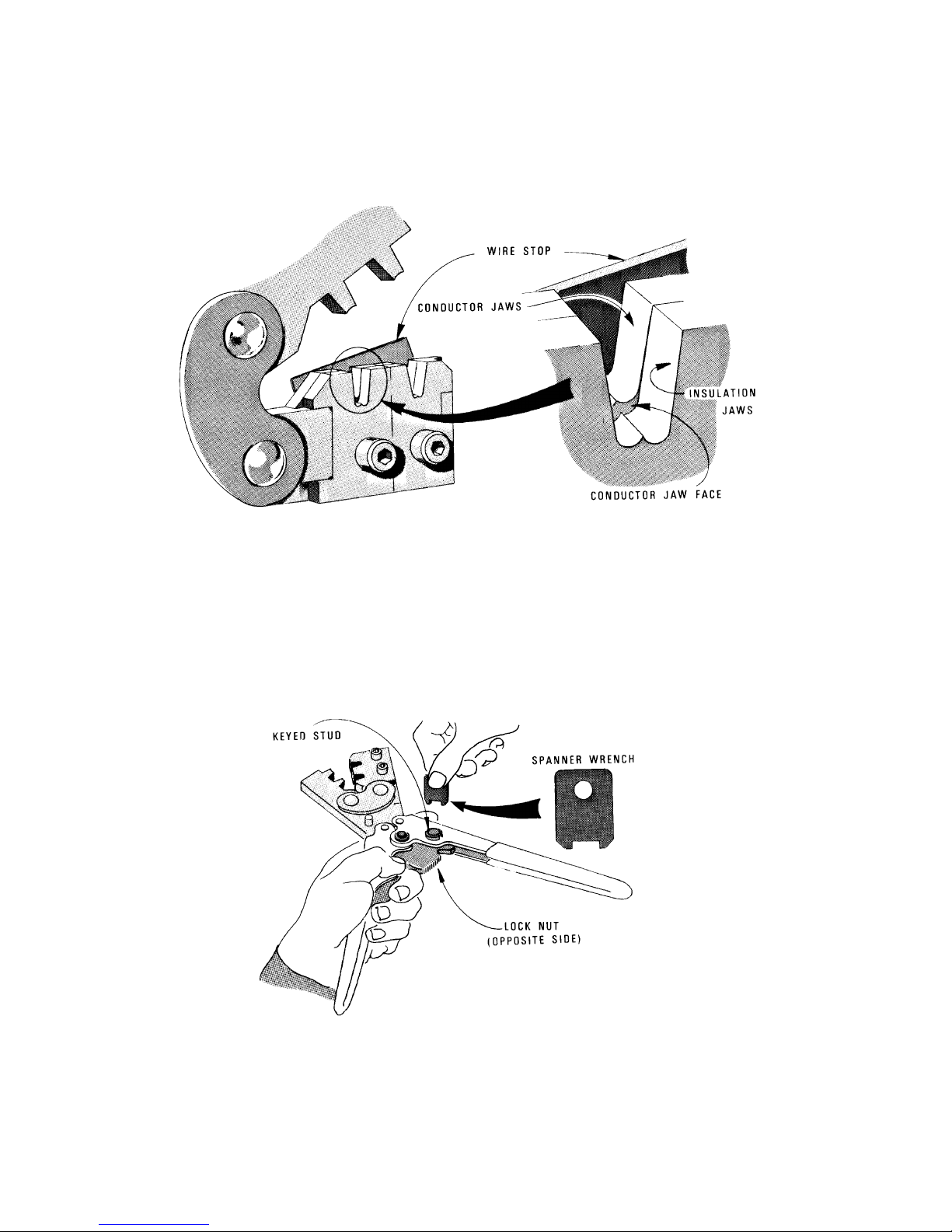
B ATCRBS TRANSPONDER KT 76C
Once the terminal is in the correct position, close the jaws gently until the terminal is held loosely in place. Push the wire
stop down so that it rests snugly behind the contact portion of the terminal.
Strip off 1/8 inch of the wire insulation and insert the wire through the insulation tabs into the conductor tabs until the insulation hits the conductor jaw face or until the conductor touches the wire stop.
Squeeze the handles until the crimp jaws close and the ratchet releases.
Straighten the terminal if necessary, then release the plier grips and remove the crimped terminal.
CRIMPING PRESSURE ADJUSTMENT
If too much or too little pressure is needed to release the crimper’s ratchet pawl at the end of the crimp stroke, the ratchet
can be easily adjusted. A spanner wrench provided with the tool can be used to loosen the lock nut, and rotate the keyed
stud clockwise for increased pressure and counter-clockwise for decreased pressure. Once the desired pressure has been
set, the lock nut must be tightened again. Newer models may have a screwdriver adjustment.
Rev 3, May 2004 IM 006-10545-0003.dwd Page 2-9
FIGURE 2-1 Crimping Tool
(Sheet 3 of 3)
Page 26
B ATCRBS TRANSPONDER KT 76C
FIGURE 2-2 KT 76C Interconnect Diagram
Rev 3, May 2004 IM 006-10545-0003.dwd Page 2-10
(Sheet 1 of 3)
Page 27
B ATCRBS TRANSPONDER KT 76C
Rev 3, May 2004 IM 006-10545-0003.dwd Page 2-11
FIGURE 2-2 KT 76C Interconnect Diagram
(Sheet 2 of 3)
Page 28

B ATCRBS TRANSPONDER KT 76C
Rev 3, May 2004 IM 006-10545-0003.dwd Page 2-12
THIS PAGE BLANK
Page 29

B ATCRBS TRANSPONDER KT 76C
Main Connector - J1 Front View
Pin Number.............................. Description
1............................................... Aircraft Ground
2............................................... 14 V Lighting (See Note)
3............................................... 28 V Lighting
4............................................... Suppression In/Out
5............................................... +5 Vdc Test Point
6............................................... -6.2 Vdc Test Point
7............................................... Reserved
8............................................... Gillham Altitude D4
9............................................... Suppression In
10............................................. External Standby
11............................................. 11-33 V dc Aircraft Power
12............................................. 11-33 V dc Aircraft Power
A .............................................. Aircraft Ground
B .............................................. Gillham Altitude B4
C .............................................. Gillham Altitude B2
D .............................................. Gillham Altitude C1
E .............................................. Gillham Altitude B1
F .............................................. External Ident
H .............................................. Gillham Altitude C4
J............................................... Gillham Altitude A4
K .............................................. Gillham Altitude A2
L............................................... Gillham Altitude C2
M.............................................. Gillham Altitude A1
N .............................................. +9 Vdc Test Point
Antenna Connector - J2
Pin Number ..................................Description
1 ...................................................Antenna
FIGURE 2-2 KT 76C Interconnect Diagram
Rev 3, May 2004 IM 006-10545-0003.dwd Page 2-13
(Sheet 3 of 3)
Page 30

B ATCRBS TRANSPONDER KT 76C
2.4 POST INSTALLATION TEST PROCEDURE
2.4.1 TRANSPONDER SYSTEM CHECKOUT
The post-installation test is used to apply power and functionally checkout the system. Successful
completion of the post-installation test verifies the proper operation of the KT 76C ATC Transponder System.
Table 2-1 is a visual inspection/check procedure that should be performed after system installation
as part of a system checkout. A post-installation test per paragraph 2.4.1.B should be performed.
In addition, the procedure should be used as a periodic maintenance inspection check.
TABLE 2-1 Inspection/Check Procedure
EQUIPMENT INSPECTION/CHECK PROCEDURE
KT 76C ATCRBS
Transponder
Antennas
A. Inspection
Perform the following inspection on the overall system:
(1) Check that cables do not interfere with aircraft controls or other equip-
ment.
(2) Check cabling for proper routing and check security of tie-down points.
Inspect and adjust cable runs to ensure that cables are not strained,
kinked, or severely twisted and are not exposed to rough or sharp sur-
faces.
B. Post-Installation Test/Operation
(1) General
A. Inspect external surface for damage
B. Check that the unit is securely installed and that retaining
mechanism is securely tightened.
C. Ensure that all connections in the mounting tray are properly mounted and secure.
A. Inspect external surfaces for damage.
B. Check that antenna is properly mounted and mounting
screws are tight.
C. Ensure that antenna coaxial cable connectors are properly
mated and secure.
Installation of the transponder system requires three stages of testing to
ensure the proper operation of the transponder. Initially, prior to the in-
stallation of the transponder and antenna, a system interwiring check
should be performed. This check verifies that the aircraft and all tran-
sponder interconnections are correct, before power is applied. After the
units are installed a visual inspection of the equipment and connections
is made.
Rev 3, May 2004 IM 006-10545-0003.dwd Page 2-14
Page 31

B ATCRBS TRANSPONDER KT 76C
(2) System Interconnect Check
To check the aircraft and transponder system interconnections proceed
as follows:
(a) Check that all cables and interwiring are installed in accordance
with the Interwiring and Cable Harness Fabrication instructions
(paragraph 2.3.3).
(b) Using the interconnect diagram (see Figure 2-2), check wiring for
proper destination, opens, and shorts.
(c) Check rf cables for insertion loss and VSWR.
(3) Visual Inspection
In conjunction with system installation, perform the inspection/check
procedure (Table 2-1 in this section).
(4) Post-Installation Test
The Post-Installation Test verifies the proper operation of the KT 76C
Transponder System. Utilizing the self-test function and a ramp tester,
this procedure is used after the system units have been installed and
thereafter as an operational check. This procedure is comprised of a
pretest setup, manual test and ramp test. The following tests are per-
formed on the ground.
(a) Pretest Setup
1) Check KT 76C system source power as follows:
a) Confirm that aircraft 11-33 V dc is operational.
b) Confirm that the aircraft panel background lighting power
source is operational by adjusting the cockpit dimmer
switch for proper cockpit panel illumination.
2) Operate appropriate aircraft circuit breakers and switches to
apply power to the system as follows:
a) Apply 11-33 V dc to transponder #1 and if applicable
transponder #2.
b) Apply primary power inputs to all that interfaces with the
transponder(s) per the system configuration.
3) Verify that all KT 76C circuit breakers are closed.
4) Allow for warm-up.
5) Verify the 4096 code is annunciated on the ATC IDENT code
display with mode select switch in the “SBY” position.
(b) Self-Test
The KT 76C transponder self-test is initiated from the front panel.
1) On the KT 76C rotate the Mode select knob to “TST”. Verify
(c) Manual Test
This test checks the ATC IDENT code switches and display.
Rev 3, May 2004 IM 006-10545-0003.dwd Page 2-15
that all segments on both the altitude and ident windows on
the display illuminate.
Page 32

B ATCRBS TRANSPONDER KT 76C
a) Verify that the ID code entry is initiated by pressing one of the
eight code selection switches. The left most significant (MSB)
display digit will change to reflect the code selection switch
that was pressed and the remaining three display digits are replaced by dashes. Subsequent ID code digits may be entered
by pressing the appropriate code selection switch.
The next displayed digit will change to reflect the code selection switch that was pressed. This sequence continues until
the last digit (LSB) is entered. The new 4 digit code should
now be displayed.
b) Verify that pressing the CLR push-button switch replaces the
last digit entered with a dash (-). Subsequent presses of the
CLR push-button will replace existing digits with dashes, until
the display is all dashes.
c) Verify that after four to six seconds of no activity on the CLR,
VFR, or Code Selection switches, the display reverts back to
the previously entered code.
(d) Conformity Inspection
Visually inspect the installed equipment to determine the use of acceptable workmanship and engineering practices. Verify that all
mechanical and electrical connections have been made properly.
(e) Ramp Test
The following test will be conducted to verify operation.
Reply Frequency - Verify that the reply frequency is 1090 +/- 3
MHz.
C. Ramp Test (optional)
This test requires the use of an ATCRBS Ramp Tester. Specific instructions
for operating the ramp tester are contained in the applicable operator’s manual. In systems with dual transponders and altitude sources configure the
system to check each function. Table 2-2 lists tests that will be performed
during ramp testing. In addition, Table 2-2 contains a brief description of each
test and the pass/fail criteria.
Rev 3, May 2004 IM 006-10545-0003.dwd Page 2-16
Page 33

B ATCRBS TRANSPONDER KT 76C
TABLE 2-2 Ramp Tests
TEST DESCRIPTION
RF Power Output
RF Frequency Measures the transmit frequency. 1090 MHz +/- 3 MHz.
ATCRBS Receiver
Sensitivity
ATCRBS SLS
Level
ATCRBS Reply
Ident Verifies Ident function is operating
Measures the effective radiated power
output from the antenna.
Measures the receiver minimum triggering
level (MTL) for a 90% reply rate.
Checks sidelobe suppression function by
varying the SLS pulse level and monitoring transponder reply rates.
Verifies Transponder replies to Mode A
and Mode C interrogations.
Measures F1 to F2 spacing and duration
of pulses.
.
PASS/FAIL CRITERIA
Minimum of 125 watts.
-73 dBm +/- 4.0 dBm.
Reply if P1 exceeds P2 by
9 dB or more.
No reply if P2 equals or
exceeds P1.
Replies to interrogations.
F1 to F2 spacing, 20.3
µsec +/- 0.1 µsec.
F1 and F2 pulse width,
0.45 µsec +/- 0.10 µsec.
Reply with SPI present in
ATCRBS Mode A only.
Rev 3, May 2004 IM 006-10545-0003.dwd Page 2-17
Page 34

B ATCRBS TRANSPONDER KT 76C
THIS PAGE RESERVED BLANK
Rev 3, May 2004 IM 006-10545-0003.dwd Page 2-18
Page 35
B ATCRBS TRANSPONDER KT 76C
Rev 3, May 2004 IM 006-10545-0003.dwd Page 2-19
FIGURE 2-3 KT 76C Transponder Installation Drawing
(Dwg No 155-06039-0000, Rev AB)
Page 36

B ATCRBS TRANSPONDER KT 76C
Rev 3, May 2004 IM 006-10545-0003.dwd Page 2-20
THIS PAGE BLANK
Page 37
B ATCRBS TRANSPONDER KT 76C
FIGURE 2-4 KA 60 Antenna Installation Drawing
Rev 3, May 2004 IM 006-10545-0003.dwd Page 2-21
Page 38
B ATCRBS TRANSPONDER KT 76C
FIGURE 2-5 Acceptable Cable Connections Drawing
Rev 3, May 2004 IM 006-10545-0003.dwd Page 2-22
(Sheet 1 of 2)
Page 39
B ATCRBS TRANSPONDER KT 76C
FIGURE 2-5 Acceptable Cable Connections Drawing
Rev 3, May 2004 IM 006-10545-0003.dwd Page 2-23
(Sheet 2 of 2)
Page 40
B ATCRBS TRANSPONDER KT 76C
Rev 3, May 2004 IM 006-10545-0003.dwd Page 2-24
FIGURE 2-6 Cable Connector Drawing
Page 41
B ATCRBS TRANSPONDER KT 76C
Rev 3, May 2004 IM 006-10545-0003.dwd Page 2-25
FIGURE 2-7 KT 76C RF Connector Assembly Drawing
Page 42

B ATCRBS TRANSPONDER KT 76C
Rev 3, May 2004 IM 006-10545-0003.dwd Page 2-26
THIS PAGE BLANK
Page 43
B ATCRBS TRANSPONDER KT 76C
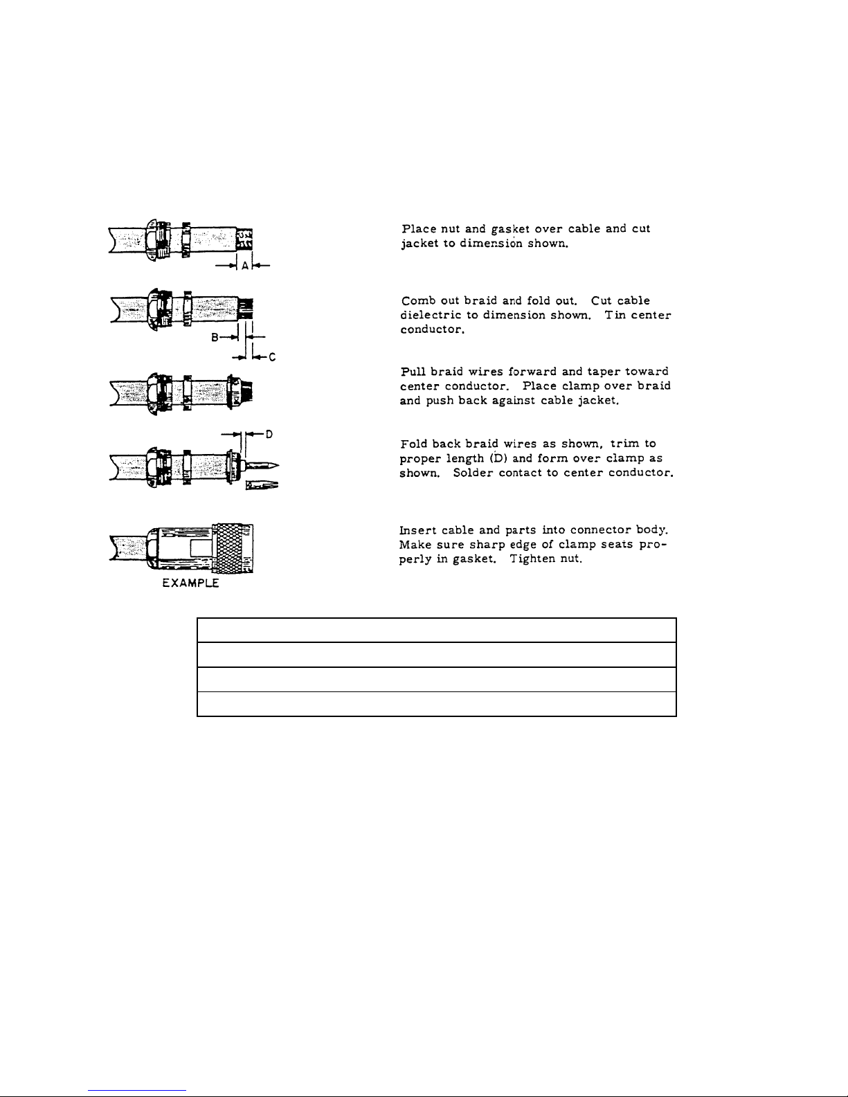
PART NUMBER SIZE DIMENSION
RG/U CABLE A B C D
024-00075-0000 393 9/32 1/8 5/32 3/64
024-00051-0060 400 9/32 1/8 5/32 3/64
FIGURE 2-8 TYPE “N” AND “C” Connector Assembly Drawing
Rev 3, May 2004 IM 006-10545-0003.dwd Page 2-27
Page 44
B ATCRBS TRANSPONDER KT 76C
FIGURE 2-9 BNC Connector Cable Assembly Drawing
Rev 3, May 2004 IM 006-10545-0003.dwd Page 2-28
Page 45
B ATCRBS TRANSPONDER KT 76C
SECTION III
OPERATION
3.1 GENERAL
The following paragraphs describe the operation of the KT 76C. Illustrations of the displays are
furnished to assist the operator in understanding the operation of the unit and also provide a visual
aid for programming sequences.
NOTE
The KT 76C, and all other avionics, should be turned
off before starting the aircraft engine(s).
3.2 DETAILED OPERATING MODES
3.2.1 FUNCTIONAL MODES
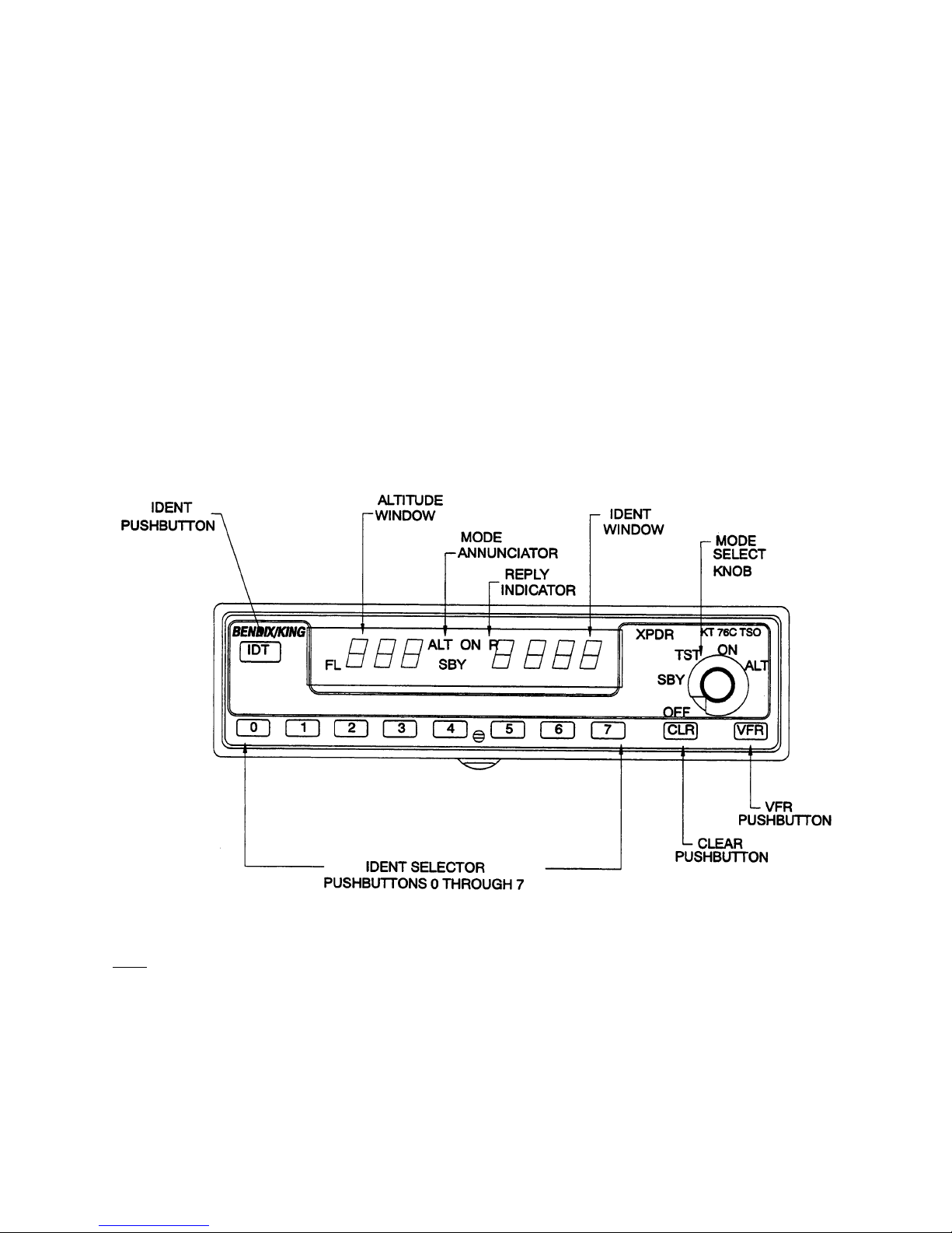
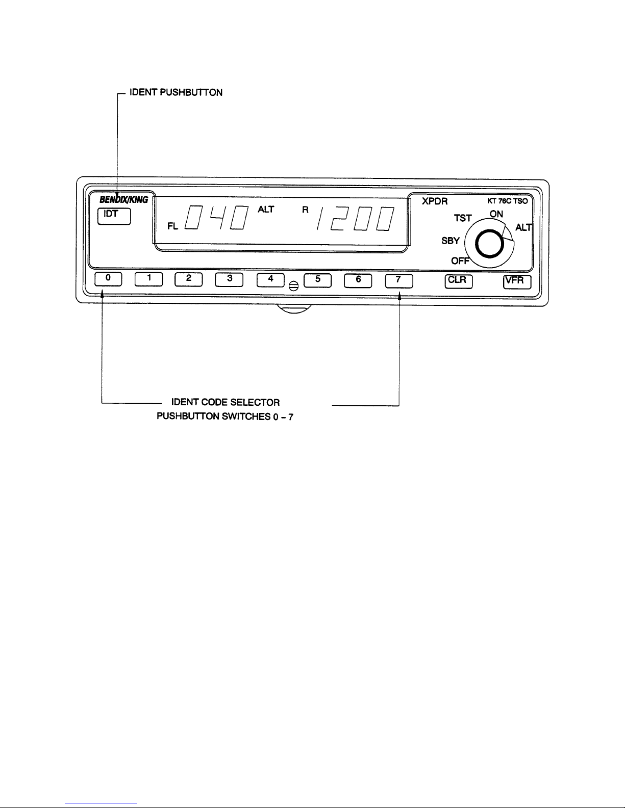
The mode is selected by the mode select knob, see the display below for the location of front panel
features (see Figure 3-1).
OFF
- The unit is not energized.
A pictorial of the “OFF” mode is not reflected; all segments are off (not lit) during the “OFF” mode.
Rev 3, May 2004 IM 006-10545-0003.dwd Page 3-1
FIGURE 3-1 Unit Functions
NOTE
Page 46
B ATCRBS TRANSPONDER KT 76C
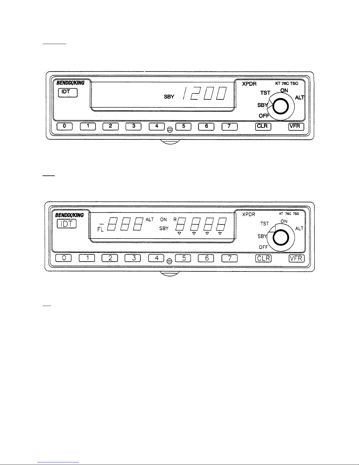
Standby
- The unit is energized, but is inhibited from replying to any interrogation. “SBY” is annun-
ciated on the display in this mode. The altitude display is blank (see Figure 3-2).
FIGURE 3-2 Standby
- The unit will illuminate all segments. The unit will remain in TST mode until the mode se-
TST
lection is changed (see Figure 3-3).
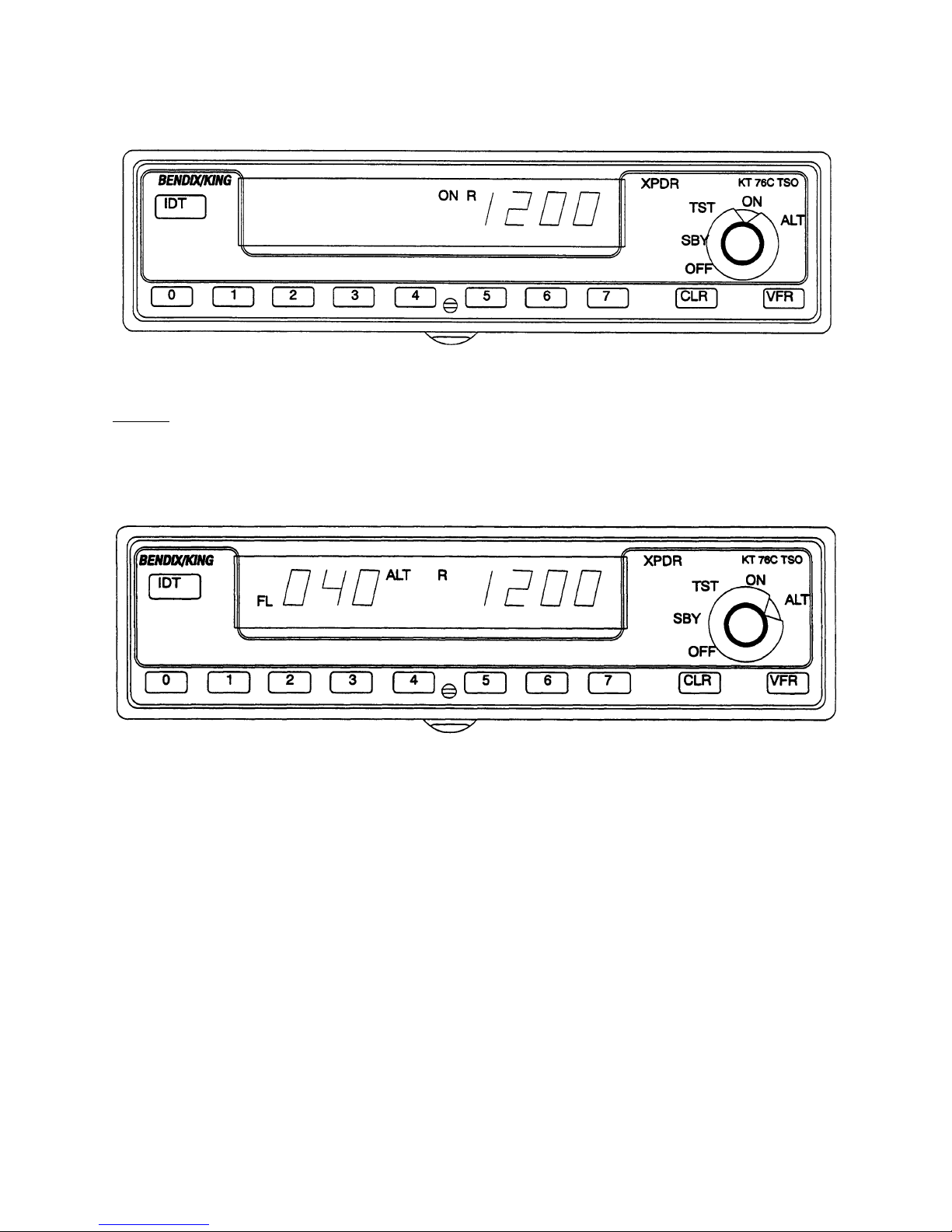
- The unit is able to reply to all valid Mode A and Mode C interrogations, however; the altitude
On
information of Mode C reply is suppressed. The altitude display is blank and the ID 4096 code is
displayed on the right. “ON” is annunciated on the display in this mode (see Figure 3-4).
Rev 3, May 2004 IM 006-10545-0003.dwd Page 3-2
FIGURE 3-3 Test
Page 47
B ATCRBS TRANSPONDER KT 76C
FIGURE 3-4 Unit ON
Altitude
- The unit is able to reply to all valid Mode A and Mode C interrogations. The altitude information will be sent in Mode C replies. The ID 4096 code will be displayed on the right and the
altitude displayed on the left. “ALT” and “FL” are annunciated on the display in this mode (see
Figure 3-5).
FIGURE 3-5 Altitude
3.2.2 FRONT PANEL OPERATION
A. IDENT
Depressing the “IDT” push button causes the special position identification
pulse (SPI) to be appended to Mode A replies for a period of 18 ± 2 seconds.
During this period the KT 76C will annunciate the “R”. An input pin is provided
on the rear connector for an external ident pushbutton (see Figure 3-6).
Rev 3, May 2004 IM 006-10545-0003.dwd Page 3-3
Page 48
B ATCRBS TRANSPONDER KT 76C
FIGURE 3-6 Ident
B. ID CODE
The 4096 Identification code, ID code, for the aircraft is displayed in the right
hand position of the display, the Ident window. There are eight pushbutton
switches (0 through 7) used to select the 4096 ID code.
The ID code may be selected in the Standby, On, and Altitude modes. Three
to four seconds after the ID code has been selected or immediately after the
“IDT” pushbutton has been pressed the new code is transmitted. The ID code
is written into nonvolatile memory so that the code will be saved during power
interruptions.
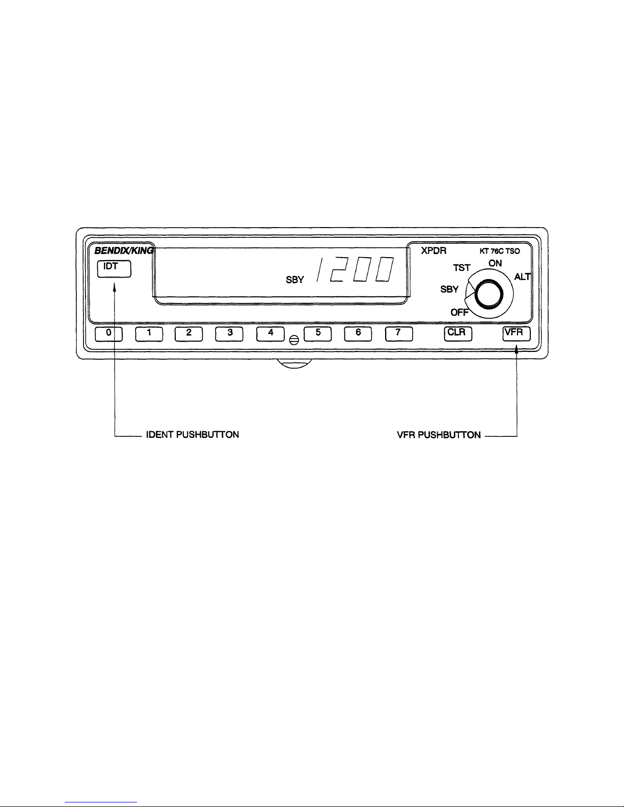
C. VFR (see Figure 3-7)
Momentarily depressing the “VFR” pushbutton causes the pre-programmed
VFR code to supersede whatever code was previously entered. The ID code
will be immediately displayed and transmitted 4 to 6 seconds later. This ID
code will be stored as the last active ID code just as if it were entered from the
front panel (see Figure 3-7).
The VFR code is programmed by the following sequence:
Rev 3, May 2004 IM 006-10545-0003.dwd Page 3-4
Page 49
B ATCRBS TRANSPONDER KT 76C
(1) Place the unit in Standby
(2) Enter in the desired VFR code with the ident code pushbutton switches.
(3) Depress the “VFR” pushbutton while holding the “IDT” pushbutton in its
depressed position.
NOTE
Pressing and holding the “VFR” Pushbutton for two
seconds will retrieve the last non-VFR 4096 code.
FIGURE 3-7 VFR
D. REPLY
The reply indicator, "R", is illuminated for 750 msec +/- 100 msec when the
transponder is replying to a valid interrogation and during the 18 ± 2 seconds
following the initiation of an Ident.
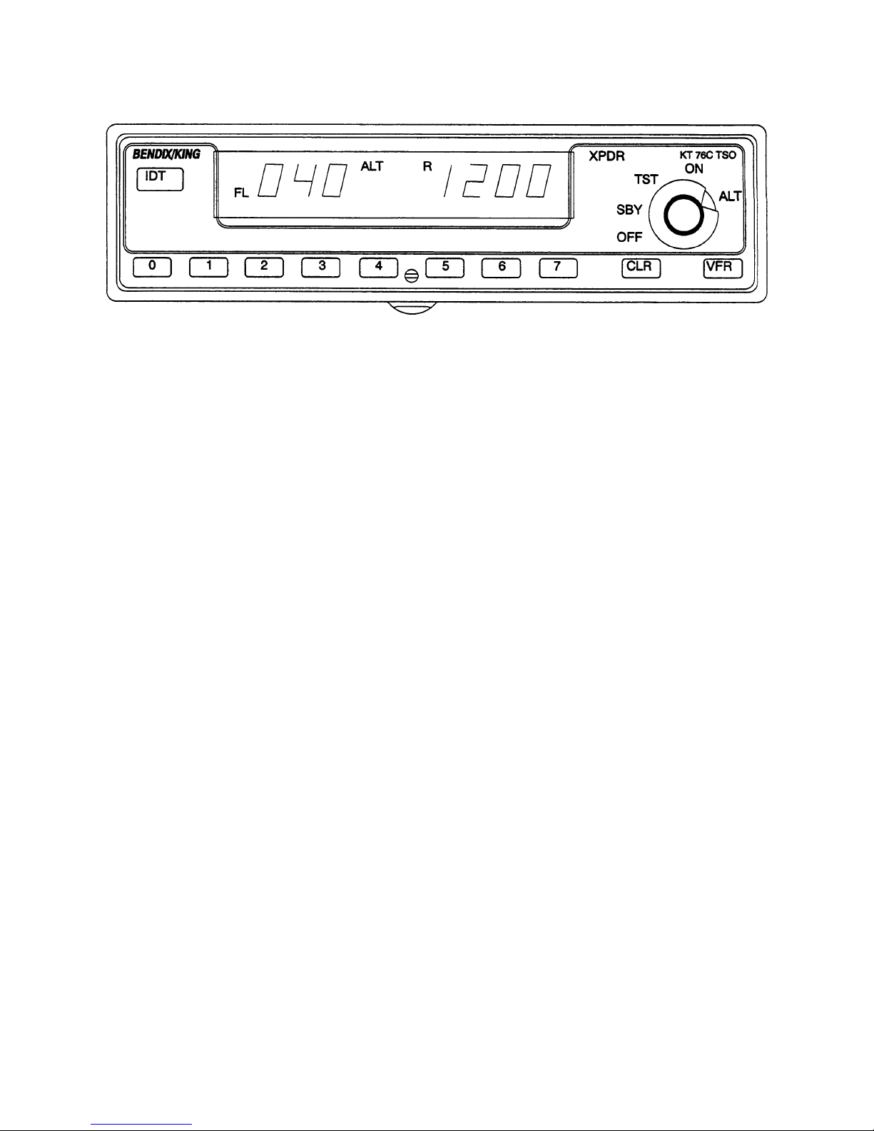
E. ALTITUDE DISPLAY
The KT 76C displays the Flight Level altitude on the left side of the display.
The display is in hundreds of feet. “FL” is annunciated to indicate Flight Level
altitude. Flight Level is a term to indicate that the altitude is not true altitude,
but barometric altitude which is not corrected for local pressure. For Example,
“FL 040" corresponds to an altitude of 4000 feet, meaning sea level pressure
of 29.92 inches of mercury.
The Flight Level altitude is only displayed when the altitude reporting is enabled, i.e. in Altitude mode. The altitude range is -1000 to 62,700 feet. If an
invalid code from the altimeter is detected dashes will appear in the altitude
window. Altitude reporting is disabled if the altitude window is blank or has
dashes (see Figure 3-8).
Rev 3, May 2004 IM 006-10545-0003.dwd Page 3-5
Page 50
B ATCRBS TRANSPONDER KT 76C
FIGURE 3-8 Altitude Display
F. DISPLAY BRIGHTNESS ADJUSTMENT
(1) Display Adjust
The display has an adjustment to compensate the brightness for different vendors and/or aging of the display. The brightness is adjusted in
the test (TST) mode.
To adjust the display brightness, perform the following steps:
(a) Turn the mode select knob to “TST”.
(b) Press the “O” pushbutton to decrease brightness.
NOTE
Each activation of the O push-button shall decrease
the display brightness by ten percent (10%). When
no carets are lit beneath the 4096 code, the display
is at its dimmest adjust setting.
(c) Press the 4 push-button to return brightness to the default factory
value.
(d) Press the 7 push-button to increase brightness.
NOTE
Each activation of the 7 push-button shall increase
the display brightness by ten percent (10%). When
all four carets are lit beneath the 4096 code, the dis-
play is at its brightest adjust setting.
(e) Remove the mode select knob from the “TST” mode to set display
parameters.
Rev 3, May 2004 IM 006-10545-0003.dwd Page 3-6
Page 51

B ATCRBS TRANSPONDER KT 76C
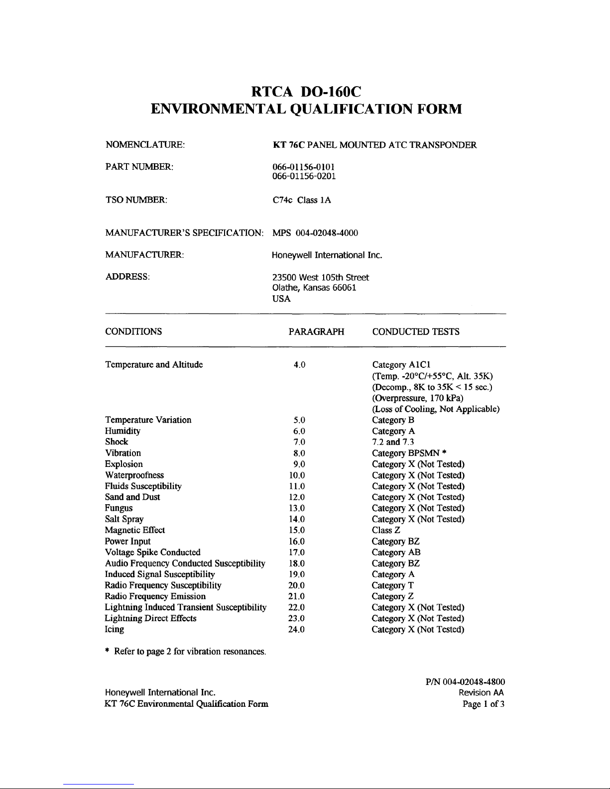
TSO APPENDIX E
ENVIRONMENTAL QUALIFICATION FORM
Rev 3, May 2004 IM 006-10545-0003.dwd Page E-1
Page 52

B ATCRBS TRANSPONDER KT 76C
THIS PAGE RESERVED BLANK
Rev 3, May 2004 IM 006-10545-0003.dwd Page E-2
Page 53
B ATCRBS TRANSPONDER KT 76C
Rev 3, May 2004 IM 006-10545-0003.dwd Page E-3
Page 54
B ATCRBS TRANSPONDER KT 76C
Rev 3, May 2004 IM 006-10545-0003.dwd Page E-4
Page 55

B ATCRBS TRANSPONDER KT 76C
Rev 3, May 2004 IM 006-10545-0003.dwd Page E-5
Page 56

B ATCRBS TRANSPONDER KT 76C
THIS PAGE RESERVED BLANK
Rev 3, May 2004 IM 006-10545-0003.dwd Page E-6
 Loading...