

Honeywell AQS 71-KAM DATASHEET
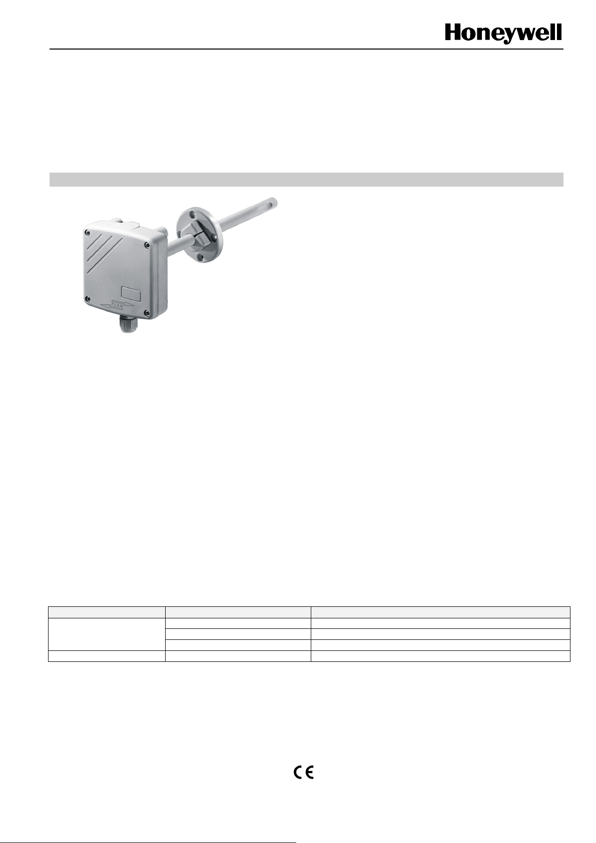
AQS 71-KAM
CO2 TRANSMITTER
GENERAL
The AQS 71-KAM CO2 Transmitter sets new standards in
CO
measurements in HVAC applications. The operation is
2
based on the infrared principle. A patented auto-calibration
procedure compensates for aging of the infrared source and
ensures outstanding long-term stability. The AQS 71-KAM
provides 0…10 V analog output and is designed for HVAC
applications (for special applications, please contact
Honeywell directly). It is suitable for direct wiring with
Honeywell Excel 20, 100, 500, and 600 controllers.
NOTE: Avoid strong mechanical stress and improper
handling. The cable gland and housing cover must
be screwed tight to avoid incorrect measurements.
Table 1. Troubleshooting
Error Possible cause Remedies
Skewed installation Air inlet and probe tip must be perpendicular to air flow.
Unrealistic results
Long response time Contamination of sensor or probe Check sensor and probe for soiling and clean, as necessary.
Low air velocity Air velocity must be > 1 m/sec (200 ft/min).
Housing not tight Seal cover and gland tightly.
PRODUCT DATA & INSTALLATION INSTRUCTIONS
FEATURES
• Patented autocalibration technology
• Outstanding long-term stability
• Fast response time
SPECIFICATION
Power supply 24 Vac, ±20% (SELV)
15…35 Vdc
Current consumption < 3 W
Ambient Limits
Operating temperature -5...+55 °C (+23...+131 °F)
Transport and storage -20...+60 °C (-4...+140 °F)
Humidity 0...95% rh, non-condensing
Safety
Protection class III as per EN 60730-1
Protection standard IP65 as per EN60529 when
probe mounted downwards,
otherwise IP20
Housing PC
Dimensions see Fig. 1 on page 2
Mounting duct
M16x1,5 cable inlet
CO
Sensor
2
Output signal 0…10 V
Load resistance R
Output scaling See sticker on housing cover
Terminal block max. 1.5 mm
Accuracy (CO2 at 20 °C [68 °F], 45% r.H., 1013 hPa)
0…2000 ppm < ± (50 ppm +2% of m.v.)
Response time
Warm-up time < 5 min
> 10 kΩ
L
τ63 < 120 sec.
2
wire diameter
Copyright © 2009 Honeywell Inc. • All Rights Reserved MU1B-0377GE51 R0109
AQS 71-KAM CO2 TRANSMITTERS
j
V
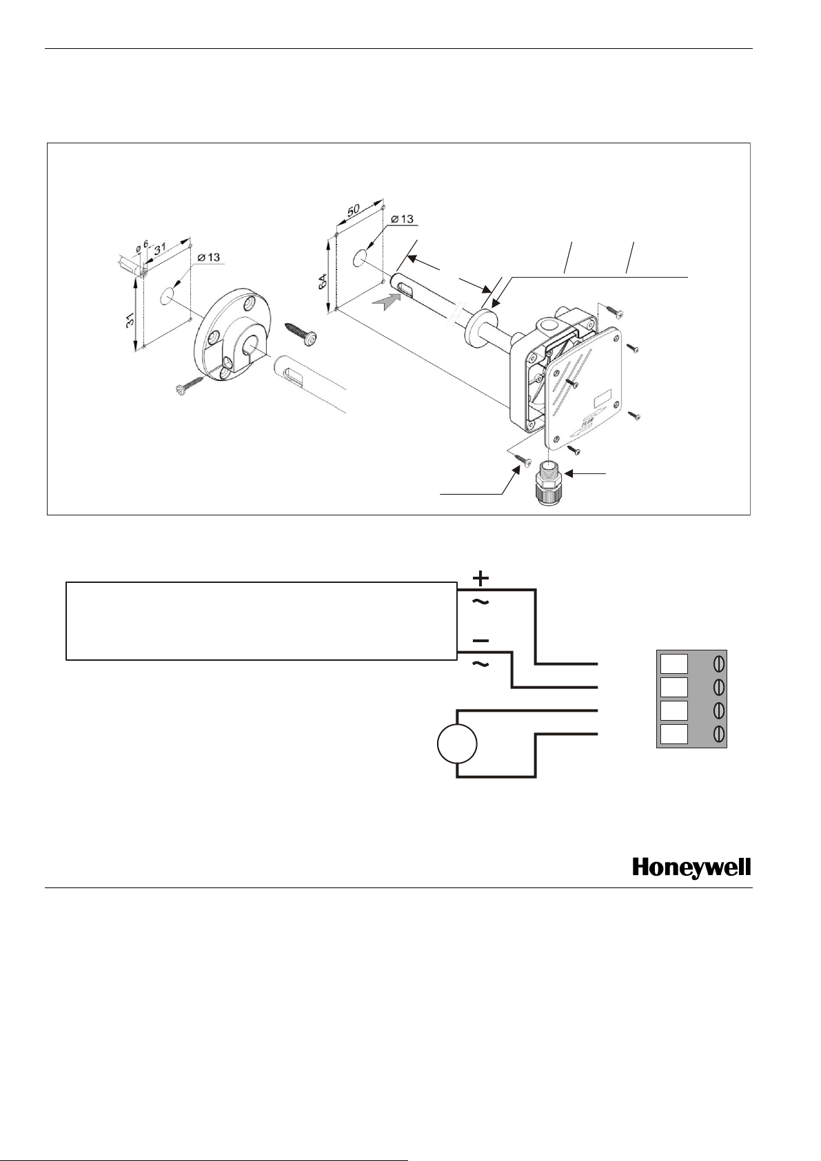
DIMENSIONS
WIRING
4 x 20 mm
Fig. 1. Dimensions (mm)
POWER SUPPLY
SPANNUNGSVERSORGUNG
24 VAC +/- 20%, 15...35 VDC
1
7
5
4 x 20 mm
Kleiner
Dichtring
small
sealing
GND
GND
M16 x 1.5
V+
CO2
petit
oint
21
3
4
Fig. 2. Connection diagram
Manufactured for and on behalf of the Environmental and Combustion Controls Division of Honeywell Technologies Sàrl, Rolle, Z.A. La Pièce 16, Switzerland by its Authorized Representative:
Automation and Control Solutions
Honeywell GmbH
Böblinger Strasse 17
71101 Schönaich
Germany
Phone: (49) 7031 63701
Fax: (49) 7031 637493
http://ecc.emea.honeywell.com
Subject to change without notice. Printed in Germany
MU1B-0377GE51 R0109
 Loading...