

Honeywell AQS 51-KAM, AQS 61-KAM DATASHEET
AQS51/61-KAM
COMBINED CO2-/TEMPERATURE
DUCT SENSOR/CONTROLLER
PRODUCT DATA
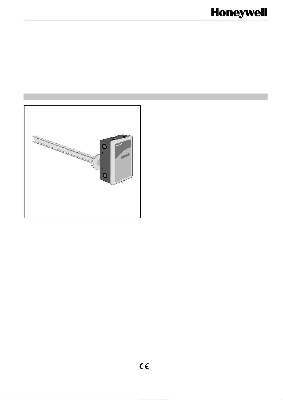
GENERAL
The AQS51-KAM and AQS 61-KAM sensors/controllers for
duct mounting measure the carbon dioxide (CO
centration and the temperature in the return or outside air.
They are used in ventilation and air conditioning systems to
control the amount of fresh outside air being supplied to the
occupants for acceptable indoor air quality and to reduce
unnecessary conditioning of outside air during lowoccupancy periods.
This Demand Controlled Ventilation (DCV) is a cost effective
solution to conserve energy and to ensure that the fresh
outside air supplied is no more than is necessary to meet the
actual requirements of the occupants at any given time.
The sensors/controllers offer separate 0(2)...10Vdc or
0(4)...20mA outputs for CO
a digital ON/OFF relay output with switching hysteresis for
alarm or other purposes.
The UART interface (RS232) for serial communication allows
a PC to be connected in order to perform maintenance
checks or reconfigurations during normal operation. If used
as a controller, each of these outputs can be configured to
and temperature and in addition
2
) con-
2
provide a more complex ventilation strategy based on a
mixture of CO
assign a number of functions, including hierarchy.
For this analog output configuration, the software program
STRATEGY is available, which is part of the User Interface
Program Software package AQS-USP22 used for recalibration, change of the measurement range or other
service or set-up purposes.
The switching setpoint and differential of the relay output for
limit monitoring or plant/system ON/OFF control can be
CO
2
adjusted within the measurement range. This output can be
used also as automatic fire threshold to switch off ventilation,
when CO
case of fire.
plus temperature measurements and to
2
levels exceed normal limit of e. g. 2500 ppm in
2
FEATURES
• CO2 measurement range 0...3000 ppm corresponding
to 0...0.3% CO
• Multifunctional unit for temperature and CO
measurement or control
• State-of-the-art Non-Dispersion-Infrared (NDIR)
technology to measure carbon dioxide gas
• Automatic drift correction (ABC-algorithm) based on a
long term evaluation provides typical zero drift check
maintenance-intervals of up to 5 years
• Standard output signals 0(2)...10 Vdc or 0(4)...20 mA
each for CO
• Programmable mixed controller signal output(s)
provides ventilation control strategies to match
exactly the application requirements
• Digital ON/OFF relay output for CO
• RS232 interface for configuration, parameter setting
or data exchange with a PC using Windows 95/98
• User interface program on diskette for service,
recalibration and change of measurement ranges
• Optional with 4-digit LCD display with the selectable
indication of:
• - CO
and room temperature alternating
2
- Error code
-concentration (ppm)
- CO
2
- Temperature (°°°°C)
- Analog Output1
- Analog Output2
. Factory-calibrated 0...2000 ppm
2
-
2
and temperature measurement or control
2
limit monitoring
2
® U.S. Registered Trademark EN0B-1023 GE02R0700
Copyright © 2000 Honeywell Inc. • All rights reserved

AQS51/61-KAM COMBINED CO2-/TEMPERATURE DUCT SENSOR/CONTROLLER
MODELS
Type Order Number
CO2 and Temperature Duct
Sensor without LCD display
CO2 and Temperature Duct
Sensor with 4-digit LCD display
TECHNICAL DATA
General
CO2 - Measurement
Temperature
Measurement
P++++I control
ACCESSORIES
Description Order Number
AQS51-KAM
AQS61-KAM
Power supply 24Vac ± 20%; 50/60Hz or 24Vdc ± 20%
Power consumption 2W
Sensor life expectancy >15 years
Maintenance interval 5 years
Self diagnostics Complete power/sensor/analog outputs internal test
Status LED indication Yellow = Maintenance required; Red = Relay activated
Power-up time ≤1 min
Ambient operating limits
- Temperature 0...50°C
- Humidity 0...95%rh (non condensing)
Operating principle Non-dispersive infrared (NDIR)
Gas sampling mode Diffusion and ∅3 mm gas inlet push-on barb
Response time 2 min (diffusion) or 10 sec (0.2 ltr/min gas flow)
Measurement range 0...3000 ppm
Converting range
Accuracy ±1% of measurement range, ±5% of reading
Pressure dependence
Annual zero drift < ±1% of measurement range
Operating principle Thermistor
Measurement range −10...60°C
Converting range
Accuracy ±0.2 K
Settings and configuration with
Service Software AQS-USP22
- Throttling range CO
- Throttling range temperature 1...10 K
- Reset time adjustment ranges 2...500 sec (factory setting: 300 sec)
2
Service Software; 3.5” Diskette
(for changing the sensing range, the
parametrization and the post calibration)
Testset
(consists of a portable gas generator for
zero-position calibration, pump, packing,
3m tube, battery and transformer)
RS Cable with built-in electronics and
adapters
0...2000 ppm = 0...10 Vdc (factory setting)
or 2...10 Vdc / 0...20 mA / 4...20 mA
+1.58% of reading per kPa deviation from normal pressure
100 kPa
0...50 °C = 0...10 Vdc (factory setting) or 2...10 Vdc / 0...20
mA / 4...20 mA
100...800 ppm
AQS-USP22
AQS-F0005
AQS3/4 or
AQS31/41
EN0B-1023 GE02R0700 2

AQS51/61-KAM COMBINED CO2-/TEMPERATURE DUCT SENSOR/CONTROLLER
Analog outputs
Digital relay output
Dimensions
Zigzag traces
(accessible after
removing the cover)
Shortage with a
screwdriver simulates
pushing of push button
Output signal
0...10 Vdc / 2...10 Vdc, impedance 100 Ω
or 0...20 mA / 4...20 mA, load ≤500 Ω
Resolution 10mV (10Bits)
D/A conversion accuracy
±2% of output voltage, +0.1 V
±2% of output current, ±0.3 mA
Protection PTC fuse (auto reset), short-circuit proof
Both outputs can be configured to any sensor mix (CO
Customization of P+I controller
temperature + digital input of 5 proportional ranges with
priorities and offsets, using the PC software STRATEGY,
Version 3)
Single pole, double throw
1A/50 Vac (50VA) or 1 A / 24 Vdc (30 W)
(SPDT) switching, potential free
contact.
Factory adjusted switching
Relay activated: ≥1000 ppm
Relay deactivated: ≤900 ppm
setpoint and differential
Sensor housing (84 x 142 x 46) mm
Sampling probe 203 mm
Toggles between the following 6 display modes on
the 4-digit display:
and temperature alternating
- CO
2
MENU Zigzag traces
- Error code
- CO
in ppm
2
- Temperature in °C
- Analog output 1
- Analog output 2
+
2
DIMENSIONS
84
25
5
55
46
0
9
2
4
1
203 42
Fig. 1 Dimensions in mm
EN0B-1023 GE02R0700
 Loading...