

Page 1
GENERAL
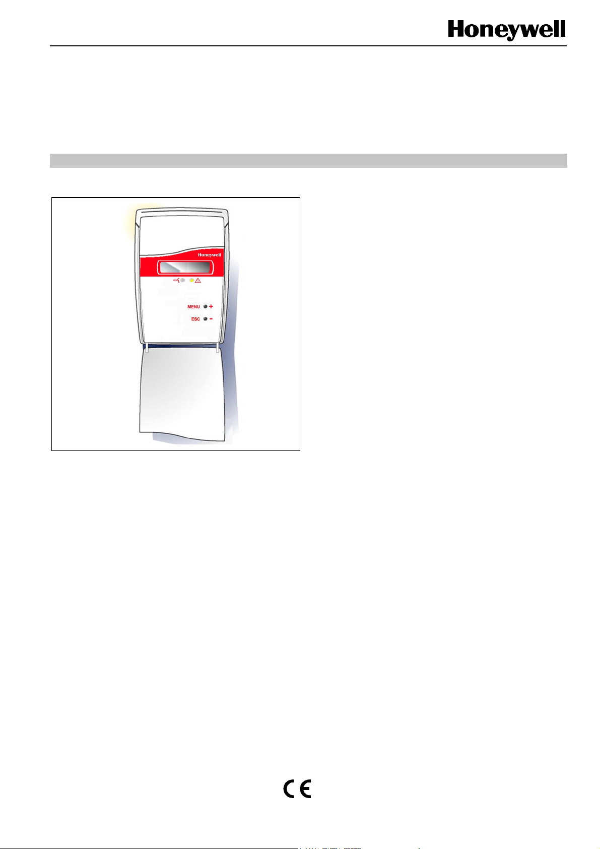
AQS51/61
COMBINED CO2-/TEMPERATURE
ROOM SENSOR/CONTROLLER
SERVICE & CHECKOUT INSTRUCTION
IMPORTANT The use of the service mode using the push
Display Mode (AQS61)
In this mode, the push button MENU is used to select the
actual value indicated on the display - CO
alternating, error code, CO
OUT1, OUT2 and OUT4, all in percent.
After restart, the display indication will always return to the
default display mode (CO
Functional Test
A simple and visual functional test can be easily performed.
Take a breath and blow onto the sensor from a distance of a
few centimeters. The sensor will detect a rapid increase in
the carbon dioxide concentration. As a result, the red LED
will light up if the CO2 level exceeds 1000 ppm (sensor
default setting).
buttons or PC is restricted to competent
trained service personnel only.
A good knowledge of the sensor/controller
functionality and the service mode is required
to perform this checkout or calibration.
and temperature
, temperature, output signal
2
and temperature alternating).
2
2
The AQS51and AQS61 temperature sensor / controller
feature two push buttons (MENU and ESC), accessible
behind the flip-down lid on the front of the sensor / controller,
providing a display selection mode and a maintenance mode
for testing and calibration purposes. In the case of the ductmounted version (AQS61-KAM), activation of the push
buttons is simulated by short-circuiting the two halves of the
zig-zag trace using a screwdriver.
The YELLOW LED will acknowledge each successful push
by a short flash. More information is shown on the LCDdisplay.
All functions available with the push buttons are also
accessible via the UART serial communication port by using
a PC together with the User Interface Program Software
AQS-USP22. This tool also provides more complex configurations, calibrations, and performance checkouts of these
sensors/controllers.
If the sensor is connected to a controller, the flow of the
ventilation system will eventually increase by changing the
fan speed or opening a damper actuator (depending on the
installation/application).
In the case of the AQS61, the present output values of the
outputs OUT1, OUT2 and OUT4 can be viewed on the LCD
by pressing MENU four to six times. The displayed values are
in %FS (percent full scale) and can be compared with the
actual output value measured using a multimeter.
® U.S. Registered Trademark EN2B-0224GE51 R0903
Copyright © 2003 Honeywell Inc. • All rights reserved
Page 2
AQS51/61 COMBINED CO2-/TEMPERATURE ROOM SENSOR/CONTROLLER
MAINTENANCE
General
The AQS51/61 is basically maintenance-free. An internal
self-adjusting calibration function takes care of normal longterm drift associated with the CO
highest accuracy, a time interval of max. five years is
recommended between CO
special situations have occurred.
A zero-point calibration can be performed using the push
button functions (for AQS61), or (in the case of a complete
overview) using a PC together with the AQS-USP22 software
version 4.0 (or higher). This software and a special RS232cable are included in the service kit AQS-F0005. The cable is
to be connected to the UART port slide connector. To change
control parameters and for recalibration (CO
perature), this PC tool must be used. The check can be done
on site without interfering with the ventilation system.
Table 1. Maintenance functions available on AQS61. Time limit refers to an internal time-out that returns the LCD and
maintenance function back to normal. ENTER is a simultaneous pressing of MENU and ESC.
Function
line
Display
sensor. To ensure the
2
calibrations, unless some
2
and tem-
2
Time-
limit
For checking/adjusting connected auxiliary equipment.
Maintenance Mode AQS61
A number of execution options as listed in Table 1 for test
functions and calibrations are available from the MAINTENANCE MENU. Access to this maintenance level is provided only from the selected display mode OUT1. By pushing
the MENU and the ESC button simultaneously as ENTER
command, the sensor/controller leaves the standard display
mode OUT1 and enters the maintenance selection mode.
With the MENU button, the required maintenance function
can be selected (see Table 1). The selected mode is shown
on the display.
Always use the ESC button to return to the previous MENU
selection mode, especially if any uncertainty exists regarding
the operation needed to return back to the DISPLAY MODE.
The ENTER command (push MENU and ESC simultaneously) may result in the execution of functions with temporary or
permanent changes to parameters affecting sensor/controller
outputs and system operation. Prior to such an execution, a
“SurE” message is shown on the display.
Functional description
Provides access to a sub-menu where output selection XX = 1...4 is done by pressing
MENU. The selected output FOXX (= OUT1...OUT4) is fixed by pressing ENTER. For XX
= 1 & 2 LO always gives 2 V / 4 mA independent of the position of the start point selection
jumper, but voltage or current according to the position of the jumper. OFF/ON is true for
1FOUtno
2bCALyes
3CALyes
the relay and open collector outputs.
FO1 & 2 LO -selected output is fixed to 2 V / 4 mA
FO3 LO -relay contact is open
FO4 LO -OUT4 is 0 V/open state
FOXX HI -selected output is fixed to 10 V / 20 mA/closed state
-sensor calibration with fresh air. An easy way to correct a zero-point error of a
CO
2
sensor. The sensor needs fresh air (380...420 ppm CO
confirmed by pushing ENTER.
Zero-point calibration of the CO
calibration instruction of zero-point calibration. The calibration must be confirmed by
pushing ENTER.
FUNCTIONS
FOUt- Fixing of Analog and Digital Outputs
This is a functional test for final control elements connected
to the outputs. When entering this operation mode, the
output is set automatically to 20%, 0% or 100% of full scale
as listed in Table 1 and Fig. 1.
Pushing the MENU and ESC button simultaneously for
ENTER, provides access to the output selection mode.
Select with the MENU button the output (F01 to F04) to be
fixed. Push MENU and ESC (ENTER) and select with the
MENU button LO or HI to fix the output to a low or high value
as requested.
). The calibration must be
2
sensor. The sensor needs zero gas. See the
2
Push MENU and ESC (ENTER) to fix the output.
To release (unfix) the temporary manual output override,
push the MENU button in fixed state.
NOTE: In the event of a power failure or power-off stage, no
automatic reset of the selected fixed state is performed. To unfix the output(s) in the power-on mode,
enter the maintenance mode FOUt and release the
fixed output(s) as described above.
EN2B-0224GE51 R0903 2
Page 3

AQS51/61 COMBINED CO2-/TEMPERATURE ROOM SENSOR/CONTROLLER
bCAL- CO2 - Sensor Baseline Calibration
with “Fresh Air”
This mode provides calibration of the CO2 sensor to background level without the need of test gas. This “fresh air”
calibration is an alternative to the more-precise “zero gas
level” calibration. The accuracy depends on how much the
actual sample gas deviates from the specified background
level of 400 ppm CO
NOTE: Take care to avoid contaminating the “fresh air” in
the sensor sample cell during and before this
calibration.
Push MENU and ESC simultaneously for the ENTER
command as long as SurE is shown on the display.
Confirm the access of the calibration mode by pushing
MENU and ESC (ENTER) again. The sensor/controller will
automatically return to the display mode.
concentration.
2
CAL- Zero-Point CO2 - Calibration
This mode is suitable for zero-level calibration of the CO
sensor. For calibration, a test gas with 0 ppm CO2 concentration is required. It is recommended to use for this purpose
the service bag AQS-F0005 which produces a CO
calibration gas by means of chemical absorption.
1. Insert the 4 mm ∅ plastic tube as far as possible into the
test gas inlet at the bottom of the wall plate.
2. Provide zero flow test gas at a rate of about 0.5 l/min for
approx. 1 min to the sensor.
3. Push MENU and ESC simultaneously for ENTER as long
as SurE is shown on the display.
4. Confirm the access of zero-point CO
pushing MENU and ESC (ENTER) again.
5. The sensor/controller will automatically return to the
display mode.
calibration by
2
-free
2
2
Test Gas Verification
Insert the plastic tube into the test gas inlet and provide a
flow test gas as described above in zero-point calibration.
Check the display reading of OUT1 (AQS61) or measure the
output value with a multimeter on OUT1 (AQS61) when it has
stabilized. The display reading or output value measured
should be equal to the used test gas.
3 EN2B-0224GE51 R0903
Page 4

AQS51/61 COMBINED CO2-/TEMPERATURE ROOM SENSOR/CONTROLLER
Fig. 1. Flow chart
Automation and Control Solutions
Honeywell GmbH
Böblinger Straβe 17
D-71101 Schönaich
Phone: (49) 7031 63701
Fax: (49) 7031 637493
http://europe.hbc.honeywell.com
Subject to change without notice. Printed in Germany Manufacturing location certified to
EN2B-0224GE51 R0903
 Loading...