

Page 1
AQS51/61
CO2 / TEMPERATURE SENSOR WITH BUILT-IN CONTROLLER
FOR WALL MOUNTING
INSTALLATION INSTRUCTIONS
GENERAL INFORMATION
The AQS51 and AQS61 CO2 / Temperature Sensors are
used to measure the concentration and temperature of
carbon dioxide in indoor air. The units can be configured as
controllers with programmable outputs for both ON/OFF relay
control and the linear control of e.g. mixed air dampers and
fans. The wall mounting housing has been designed with
snap-in features to minimize installation time.
The units can be directly connected to common VAV
(Variable Air Volume) controllers, Direct Digital Control (DDC)
devices, or standalone control systems. The linear output
functions are pre-programmed as CO
transmitters. In addition, the AQS51 and AQS61 have a relay
output pre-programmed as a CO
modified from a PC (Windows 95, 98, NT) using the AQSUSPxx (version 4.0 or higher) software together with the
AQS3/4-CABLE communication cable.
and temperature
2
limiter. All functions can be
2
® U.S. Registered Trademark EN1B-0189GE51 R0102
Copyright © 2002 Honeywell Inc. • All rights reserved
Page 2
AQS 51/61 CO2 / TEMPERATURE SENSOR WITH BUILT-IN CONTROLLER
DIMENSIONS
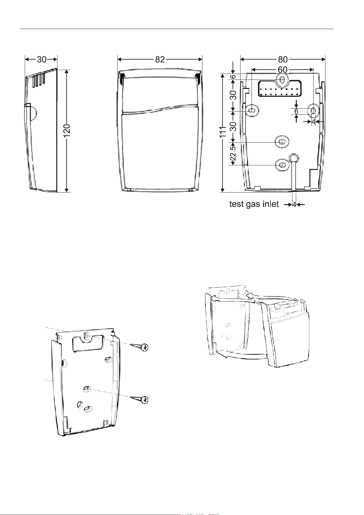
Fig. 1. Dimensions (in mm) of AQS 51/61 (all oval holes have the same size)
WALL MOUNTING
Mounting the Wall Plate
The wall plate mounts vertically on the wall or on the wall
wiring outlet box.
1. Position and level the wall plate on the wall and use a
pencil to mark the mounting holes.
2. Remove the wall plate from the wall, drill two holes for
M4 screws in the wall as marked, and insert dowel into
the holes.
3. Position the wall plate over the holes and pull the wires
through the wiring opening.
4. Loosely insert the mounting screws into the holes and
tighten them (see Fig. 2).
Mounting System Unit onto Wall Plate
1. Bend the wires to the top to allow wiring connections to
the terminals.
2. Engage first the top tabs of the sensor/controller protection case into the top holes of the wall plate and then
press the lower edge of the case onto the wall plate to
latch (see Fig. 3). Be careful not to damage the temperature sensor.
Fig. 3. Mounting the sensor/controller onto the wall plate
Fig. 2. Mounting of the wall plate
EN1B-0189GE51 R0102 2
Page 3
AQS 51/61 CO2 / TEMPERATURE SENSOR WITH BUILT-IN CONTROLLER
ll
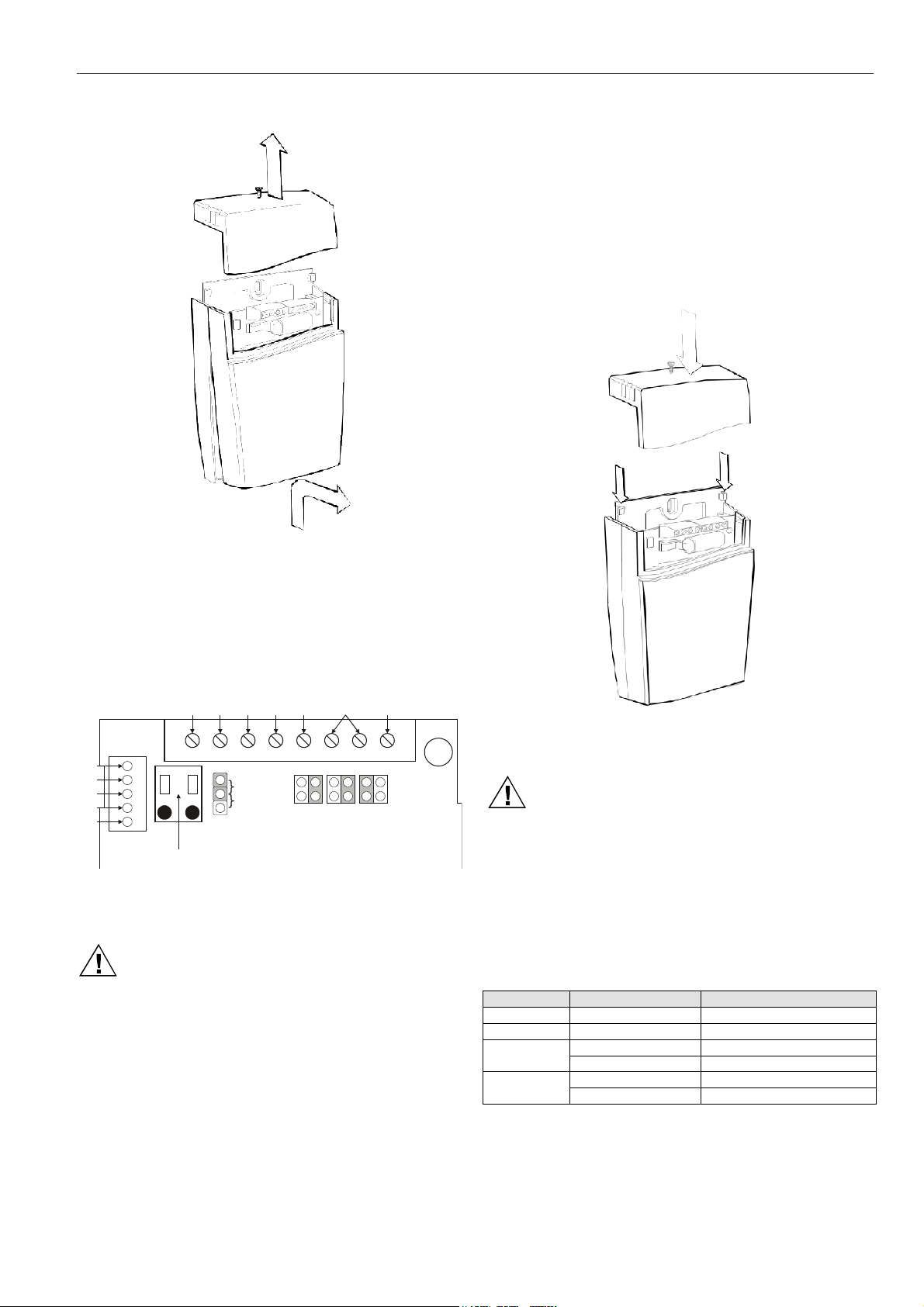
Removing System Unit from Wall Plate
Fig. 4. Removing the wiring terminal cover and the
sensor/controller
1. Loosen the screw on top of the wiring terminal cover and
remove the wiring terminal cover from the wall plate (see
Fig. 4).
2. Pull out first the bottom of the sensor/controller, then
disengage the top tabs and remove the top.
separate floating transformers for sensor and controller /
DDC system.
1. Connect the correct wires to the terminals and securely
tighten each terminal screw. Follow the actual job wiring
diagrams if available or refer to Table 2 for terminal
designations. A sticker is located on the inside of the
terminal cover that identifies the terminals (see Fig. 5).
All wiring must comply with local electrical codes,
ordinances and regulations.
2. Place the wiring terminal cover by fitting the notches of
the cover into the hooks of the wall plate. Tighten the
locking screw (see Fig. 6).
Wiring
y-open
norma
relay
current
voltage
OUT1 OUT2 OUT4
open
current
voltage
collector
voltage
R/T
GND
+5 V
RXD
TXD
G+ G0
digital input
startpoint
selection
jumper
OUT1
0%
20%
OUT2 OUT4M
Fig. 5. Connections and jumpers on AQS51/61. The
shaded positions represent the default settings
CAUTION
Check that all wiring is correctly completed before
turning the power on! Do not connect wires when the
unit is powered. Do not detach the sensor/controller
from the wall plate when the power is on!
The AQS51/61 signal ground (M) is not galvanically
separated from the power supply G0 terminal. If the analog
output signals are connected to controllers or DDC systems,
these units must have the same ground. If necessary, use
Fig. 6. Installing the wiring terminal cover
Electrical Connections
CAUTION
The power supply must be connected to G+ and G0.
G0 is considered as system ground. If the analog
output is connected to a controller, the same ground
reference must be used for the AQS51/61 unit and for
the control system! Unless different transformers are
used, special precautions must be taken!
NOTE: The signal ground of the AQS 51/61 is not
Terminal Default output Default output range
OUT1 0...10 Vdc 0...2000 ppm CO
OUT2 0...10 Vdc 0...50 °C
Relay
OUT4
galvanically separated from its power supply!
Table 1. Default output configurations for AQS51/61
2
closed > 1000 ppm CO
open < 900 ppm CO
closed > 2000 ppm CO
open < 1900 ppm CO
2
2
2
2
EN1B-0189GE51 R01023
Page 4

AQS 51/61 CO2 / TEMPERATURE SENSOR WITH BUILT-IN CONTROLLER
Table 2. Electrical terminal connections for AQS51/61
Connection
terminal
G+ power (+) 24 Vac/dc+ (±20%), 3 W 2 W without output load
G0 power ground (-) 24 Vac/dc-
OUT1 analog output 1 (+)
OUT2 analog output 2 (+) same as output 1
M signal ground (-) connected to G0 via PTC fuse See note 1!
Relay normally open
OUT4
DI1 digital input 1
Function Electrical data Remarks
0...10 Vdc or 0...20 mA
2...10 Vdc or 4...20 mA
According to positions of OUT1 and start
point of jumpers
According to positions of OUT2 and start
point of jumpers
analog output 4 (+)
or open collector
contact-free relay; min. load: 1 mA / 5 V;
rated load: 0.5 A / 125 Vac, 1 A / 24 Vdc
0...10 Vdc; max. 0.5 A, 60 Vdc / 40 Vac
(half-wave rectifier protection)
closed contact current: 1 mA, open
voltage contact: max. 5 V
Triggered by register OUT3
According to positions of OUT4. See also
notes 2 and 3!
Do not apply any voltage to this input!
2
2
1
NOTE 1:
The ground terminal is used as negative power supply DC input or AC phase ground G0 (half-wave rectifier). The
signal ground M, protected by a PTC resistor, is the same as power ground G0 (permitting a ”3-wire” configuration). A
single transformer may be used for the entire system.
NOTE 2:
AQS51/61 can deliver both a voltage or a current loop for OUT1/OUT2. For OUT4 a voltage output or an open
collector output is selected with jumper OUT4. To change between voltage and current output mode the hardware
jumpers are used. There is one jumper for OUT1 and one for OUT2, so that one output can be a voltage output and
the other a current output. Both voltage output and current output can have start points 0 % (0-10 VDC or 0-20mA) or
20% (2-10 VDC or 4-20mA). The same start point is used for both outputs. See Table 1.
NOTE 3:
The open collector's current is internally returned to the G0 terminal.
Output Configurations
The sensors/controllers are supplied from the factory (unless
otherwise ordered) with 0...10 Vdc linear outputs for OUT1
and OUT2 and for OUT4 when it is used as an open collector
output (see Table 1). If different outputs are needed for the
application, these have to be configured before the unit is
Table 3. Configuration jumpers for AQS51/61
Jumper Position Function
start point
of the
selection
jumper
OUT1
OUT2
OUT4
0%
20%
current Connection in the "current" position provides a 0/4...20 mA output range for OUT1.
voltage Connection in the "voltage" position provides a 0/2...10 Vdc output range for OUT1.
current Connection in the "current" position provides a 0/4...20 mA output range for OUT2.
voltage Connection in the "voltage" position provides a 0/2...10 Vdc output range for OUT2.
current
voltage Connection in the "voltage" position provides a 0...10 Vdc output range for OUT4.
Jumper top position provides a 0 Vdc or 0 mA start point for OUT1 and OUT2 (0...20 mA or 0...10 V).
OUT4 has a 0 V output start point when jumper OUT4 is in the “voltage” position (0...10 V).
Jumper bottom position provides a 2 Vdc or 4 mA start point for OUT1 and OUT2 (4...20 mA or
2...10 V). OUT4 has a 0 V output start point when jumper OUT4 is in the “voltage” position (0...10 V).
Connection in the "open collector" position provides an open collector output. Max. 0.5 A, 60 Vdc /
40 Vac (half-wave rectifier).
powered up. To select alternative output ranges, position the
four jumpers as required for the application. Each jumper
selection is independent from the others, except in the case
of the “Start point selection” jumper, which affects both linear
outputs (i.e. OUT1 and OUT2).
Push Button Operation for AQS61
This sensor has two push buttons, MENU and ESC, located
on the front panel behind the flip-down lid. The YELLOW
LED will acknowledge a successful push by a short flash.
The push button MENU is available for selection of display
value or maintenance commands, whereas ESC is available
to escape back from a selected level.
Display Modes
In the DISPLAY MODE, the push button MENU is used to
select the value to be indicated on the display: CO
EN1B-0189GE51 R0102 4
con-
2
centration and temperature (alternating), error code, CO
,
2
temperature, output 1, output 2, or output 4. After the device
is powered up, the display will always return to the default
display mode
Page 5

AQS 51/61 CO2 / TEMPERATURE SENSOR WITH BUILT-IN CONTROLLER
Maintenance Level
A number of execution options are available from the
MAINTENANCE MENU (see Table 4). This level is accessed
only from the display mode in the OUT1 % selection. Simultaneously pressing two push buttons restricts access,
intended for competent trained service personnel only (see
Fig. 7). The ENTER command is issued by simultaneously
pressing MENU and ESC.
Table 4. Maintenance functions available on the AQS61
Function
line
Display Time limit
1
For checking/adjusting connected auxiliary equipment.
Provides access to a sub-menu in which output selection XX = 1...4 is done by pressing
MENU. The selected output FOXX (= OUT1-4) is fixed via ENTER
provides 2 V /4 mA regardless of the position of the start point selection jumper, but
1FOUtno
voltage or current according to the position of the jumper. OFF/ON is true for the relay and
open collector outputs.
FO 1,2 LO: selected output is fixed to 2V / 4 mA
FO 3 LO: relay contact is open
FO 4 LO: OUT4 is 0V/open state
FOXX HI: selected output is fixed to 10V/20mA/closed state
CO
-sensor calibration with fresh air. An easy way to correct a zero-point error of a sensor.
2bCALyes
2
The sensor needs fresh air (380...420 ppm CO
pushing ENTER
3CALyes
1
The phrase "time limit" refers to an internal time-out which returns the LCD and the maintenance function back to normal.
2
ENTER is achieved by simultaneously pressing MENU and ESC.
Zero-point calibration of the CO
instruction of zero-point calibration. The calibration must be confirmed by pushing ENTER.
Always use the ESC button to return to the MENU selection
block in the left-hand portion of Fig. 7. Several pushes of the
ESC button may be needed to return to the DEFAULT mode.
The ENTER command (press MENU and ESC simultaneously) may result in the execution of functions with temporary or
permanent changes to parameters affecting sensor/controller
outputs and system operation.
Functional description
2
. For XX=1,2 LO always
). The calibration must be confirmed by
2
sensor. The sensor needs zero gas. See the calibration
2
Fig. 7. Push-button menu flow-chart for the AQS61
EN1B-0189GE51 R01025
Page 6

AQS 51/61 CO2 / TEMPERATURE SENSOR WITH BUILT-IN CONTROLLER
FUNCTIONAL TEST OF THE AQS51/61 CO2 AND TEMPERATURE SENSOR
Functional Test
The unit has two LED’s - yellow and red - on the front panel
(found under the front lid). These LED’s indicate the
controller's status.
Yellow LED - ”Call for maintenance” is lit if an error flag has
been set or the measurement is out of range. In the case of
the AQS61, this information is also shown on the display by
the wrench icon. Any push button press, or executed maintenance function, is acknowledged by this LED lighting up.
Red LED - ”Relay active” is lit when the relay has been
activated (contact closed).
A simple and visual functional test can easily be performed.
Take a breath and blow the air from a distance of a few
centimeters onto the sensor. The sensor will detect a rapid
increase in the carbon dioxide concentration. As a result, the
red LED will light up as the CO
(sensor default setting). If the sensor is connected to a
controller, the flow of the ventilation system will eventually
increase by change of the fan speed or opening of a damper
actuator (depending on the installation/application).
In the case of the AQS61, the present output values of the
outputs OUT1, OUT2 and OUT4 can be viewed on the LCD
by pressing MENU four to six times. The displayed values are
in %FS (percent full scale) and can be compared with the
actual output value measured with a multimeter.
level exceeds 1000 ppm
2
Test Gas Verification
Insert 4 mm plastic tubing in the test gas inlet at the bottom
of the wall plate. The plastic tubing should be inserted as far
as possible into the inlet. Flow test gas at a rate of about 0.5
liter/minute. Check the display (or OUT1 with a multimeter) to
read the CO
NOTE: The sensor accuracy is defined at continuous
-value when it has stabilized.
2
operation (at least 3 weeks after installation).
Self Diagnostics
The system contains complete self diagnostic procedures. A
full system test is executed automatically every time the
power is turned on. In addition, the sensor probes are constantly checked against failure during operation by checking
the valid dynamic measurement ranges. All EEPROM
updates (initiated by the sensor itself or by external connections) are checked by subsequent memory read back and
data comparisons. These different system checks return
error bytes to the system RAM. If any error is detected, the
yellow LED will light up until the error has vanished and the
error flag is reset. “Warm up” and “Out of Range” are the only
bits that are reset automatically after return to normal state.
All other error bits have to be reset manually after return to
normal state – either by pushing the MENU and ESC buttons
simultaneously for ENTER (AQS61 only) or by power off and
restart.
The error code number Exxx can be made to appear on the
LCD (AQS61) by pressing the ”MENU” push button.
Descriptions of the different codes are listed below.
EN1B-0189GE51 R0102 6
Page 7

AQS 51/61 CO2 / TEMPERATURE SENSOR WITH BUILT-IN CONTROLLER
Bit # Error code Error description Suggested action
0 N/A Fatal error: The yellow LED flashes con-
tinuously. The push buttons do not function.
12 Reserved
2 4 Âlgorithm error: An incorrect EEPROM
configuration is indicated.
3 8 Output error: Detected errors during output
signal calculation and generation.
4 16 Self diagnosis error: May indicate the need of
zero-point calibration or sensor replacement.
6 64 Memory error: Non-fatal error during memory
operations.
7 128 Warm-up state: Is always set after power-up or
power failure. Resets after restart sequence.
Try to restart the sensor by turning the power off and
on again. Contact local distributor.
Try to restart the sensor by turning the power off and
on again. Check detailed settings and configuration
with AQS-USP software version 4.0 and higher.
Contact local distributor.
Check connections and output loads. Check detailed
status of outputs with AQS-USP software version 4.0
and higher.
Check detailed self-diagnostic status with AQS-USP
software version 4.0 and higher. Contact local
distributor.
Check detailed settings and configuration with AQSUSP software version 4.0 and higher.
If it doesn't disappear within 30 seconds, check power
stability.
NOTE: One of the probes is out of range. Occurs, for instance, during over-exposure of the CO2 sensor, in which case the
error code will automatically reset when the measurement values return to normal. Could also indicate the need of
zero-point calibration. A background calibration using push button function ”bCAL” will remedy this error (a more exact
zero-point calibration using ”CAL” may be performed later, if required). If the CO
code remains, the temperature sensor might be broken.
readings are normal but the error
2
REMARK:
If several errors are detected at the same time, the different error code numbers will be added together into one single
error code.
Maintenance
Basically speaking, the AQS51/61 is maintenance-free. An
internal self-adjusting calibration function takes care of
normal long-term drift associated with the CO
sensor. To
2
Limited Warranty
This product has been accurately tested and examined for
proper operation. Please operate this product only in
accordance with the instructions.
ensure the highest accuracy, a time interval of max. five
years is recommended between CO
calibrations unless
2
some special situations have occurred. A zero-point
calibration can be performed using the push button functions
(for AQS61), or for a complete overview, by using a PC
together with the AQS-USPxx software version 4.0 (or
higher). This software and a special RS232-cable are
The warranty period of the product against defects in work-
manship and material is one year from date of purchase by
the original owner. If the product should become defective
within this warranty period, the customer owns the right for
repair or exchange the product free of charge. Please contact
your retailer for further information.
included in the AQS-F0005 service kit. The cable is to be
connected to the UART port slide connector (see Fig.9). For
changing control parameters and re-calibration (CO
and
2
temperature), this PC tool must to be used. The check can
be done on site without interfering with the ventilation system.
If, for some reason, the printed circuit board (PCB) needs to
be removed, special precautions must be taken in order to
avoid damaging the temperature probe. When putting the
PCB back into the protective housing, the temperature probe
must be gently positioned in the small probe compartment
(see Fig. 8)!
The retailer is not responsible for any consequential loss or
damages, which may occur by reason of purchase and use
of this product. The warranty is, in any event, strictly limited
to the replacement/repair of the product.
This product is in accordance with the EMC Directive
89/336/EEC and the Low-Voltage Directive 73/23/EEC,
including amendments by the CE-marking Directive
93/68/EEC.
This product fulfills the following requirements:
• EN50081-1
• EN55011(B)
• EN50082-2
• EN61000-4-2.-3.-4.-5. Level 3
EN1B-0189GE51 R01027
Page 8

AQS 51/61 CO2 / TEMPERATURE SENSOR WITH BUILT-IN CONTROLLER
Fig. 8. Positioning the temperature sensor (the black dot), enlargement at right
Home and Building Control Home and Building Control Home and Building Control
Honeywell Inc. Honeywell Limited-Honeywell Limitee Honeywell AG
Honeywell Plaza 155 Gordon Baker Road Böblinger Straβe 17 manufacturing
P.O. Box 524 North York, Ontario D-71101 Schönaich location certified to
Minneapolis, MN 55408-0524 M2H 3N7 Germany
USA Canada
http://www.honeywell.com http://www.honeywell.ca http://europe.hbc.honeywell.com
EN1B-0189GE51 R0102 printed in Germany Subject to change without notice
 Loading...