

Page 1
69-2119-05
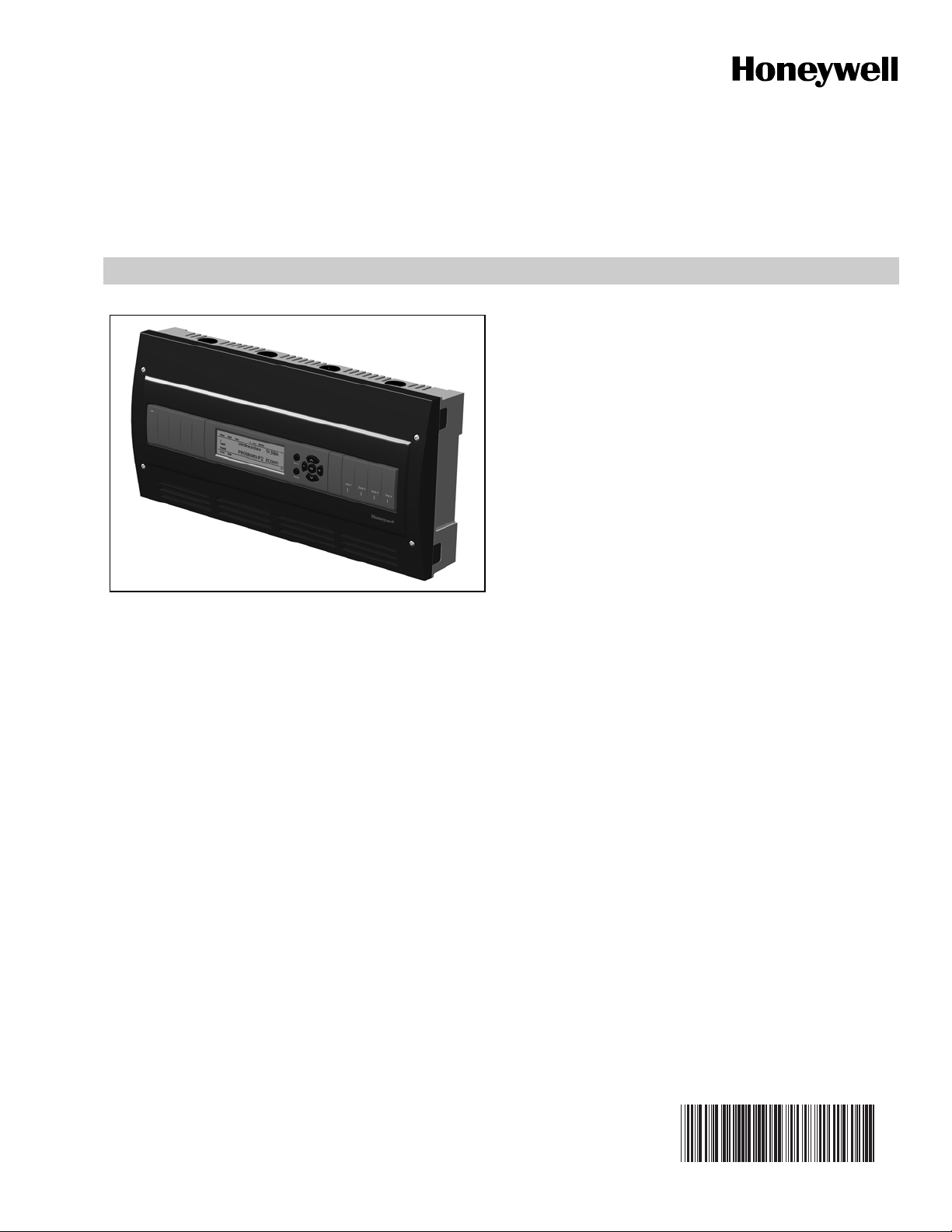
AQ25A Series Programmable Boiler
Control Panels
FEATURES
The AQ25A Series Programmable Boiler Control Panels have
the following features:
• Boiler supply and return temperature sensors
• Outdoor temperature sensor
• Zoning equipment (zone valves or pumps)
• Availability of two Zoning Modules: the AQ15740B, for
zoning with 24 Vac zone valves with end switches, and
the AQ15540B, for zoning with either line voltage
circulators or 24 Vac zone valves without end
switches.
• An AQ10X38 transformer (power supply module),
which connects to 120 Vac power and supplies 24 Vac
power to the Control Module and Zoning Modules
• 4-zone or 8-zone Expansion Zo ni ng Panels, up to a
maximum of 16 zones
PRODUCT DESCRIPTION
The AQ25A Series of Programmable Boiler Control Panels
consists of a transformer, a boiler/DHW Control Module, and a
4-zone Zoning Module, all contained within an AQ2000 panel
enclosure. The boiler/DHW Control Module, controls the boiler
and domestic hot water (DHW) functions, as well as
coordinating the overall operation of the hydronic system.
• Communications between co m po nents via the
AQUATROL
wiring.
• AQ15A Boiler/Domestic Hot Water Control Module,
which controls boiler and DHW functions, as well as
provides overall management of the hydroni cs system
®
network, using communication bus
PRODUCT DATA
AQ25A Control Panels can control a maximum of 16 zones by
connecting additional Expansion Zoning Panels to the AQ25A
Control Panel. Each Expansion Zoning Panel is configured
with its own bank of DIP switches.
Contents
Specifications ................................................................... 2
1 Installation Preparation .................................................. 3
2 Mounting ........................................................................ 5
3 Wiring Procedure ........................................................... 5
4 Program and Configure the Control Panel .................... 14
5 Test and Check Out the Installation ............................... 18
6 Purge Air from all System and Zone Piping .................. 19
7 Document and Keep a record of all System Settings .... 19
Troubleshooting ................................................................ 20
Appendix .......................................................................... 23
User Menu .............................................................. 23
Installer Menu ......................................................... 30
Page 2

AQ25A SERIES PROGRAMMABLE BOILER CONTROL PANELS
SPECIFICATIONS
The AQ25A Programmable Boiler Control Panels and
corresponding attached equipment are listed in Table 1.
Table 1. AQ25A Series Control Panel Models.
Corresponding
Control Panel
AQ25A42B AQ15A10B AQ15540B
AQ25A44B AQ15A10B AQ15740B
Application: Controls zoning operations, and provide boil er
and DHW management for hydronic zoning systems.
Power and Electrical Ratings:
Power Supply: 120 Vac / 60Hz
Auxiliary Pump Output Rating: Dry contact output,
120 to 240 Vac, 5A, 1/3 HP
Auxiliary Low Voltage Output Rating: 24 Vac, 0.5A,
12VA
Boiler (T-T) Output Rating: 24 Vac, 0.5A, 12VA
Boiler Pump (C1-C2) Output Rating: 120 Vac 5A, 1/3HP
DHW Pump/Valve Output Rating: 120 Vac 5A, 1/3HP
B–B Communication Bus Terminals: Low voltage,
Class II, 2-wire polarity-insensitive, digital
communicating link to other Control or Zoning modules
Electrical Connections (Line Voltage): Wire-clamp
screw terminals; maximum 2 x 14 AWG each on line
voltage terminals
Environmental Ratings:
Control and Zoning Panel Temperature Rating: 32°F to
130°F (0°C to 55°C)
Operating Humidity Range (% RH): 5 to 90% RH, non-
condensing
Temperature Ratings:
Boiler Differential: 2° to 41° F (1° to 23° C), or AUTO
Boiler (Supply) Minimum Control Temperature:
OFF, 59° to 180° F (OFF, 15° to 82° C)
Boiler (Supply) Maximum Control Temperature: OFF,
120°F to 225°F (OFF, 49°C to 107°C)
Return Minimum Control Temperature: OFF, 80°F to
180°F (OFF, 27°C to 82°C)
Control Module
Corresponding
Zoning Module
Sensor Temperature Rating: -58°F to 230°F (-50°C to
110°C)
Sensor Temperature Rating: -58°F to 230°F (-50°C to
110°C)
Warm Weather Shut Down (WWSD) Temperature:
OFF, 35°F to 100°F (OFF, 1°C to 38°C)
Cold Weather Shut Down (CWSD) Temperature: OFF,
32°F to 100°F (OFF, 0°C to 38°C)
Inputs/Outputs:
Auxiliary (Demand) Input: External dry contacts
connection only
DHW Demand Input: External dry contacts connection
only
Heat Demand (Thermostat R-W) Input: External dry
contacts connection only
Heat Demand Input External dry contacts connection
only
Modulating Output: 0-10 or 2-10 Vdc for modulating
boiler
R–C Input (on Control and Zoning Modules): 24 Vac
Class II
R–C Output (on transformer): 38 VA, 24 Vac Class II
Interface and Timings:
User Interface (Setting, Programming): LCD Display
and a 7-button keypad
Setback Program: 7 day, up to 2 setback periods/day.
DHW Valve Open: 0-230 seconds, before boiler loop
pump is energized.
DHW Purge: Yes/No; selects whether purge is applied
after a DHW demand is served
Boiler Heat Post Purge: Off, 10 seconds to 30 minutes
(factory default is 30 seconds)
Pump/Valve exercise: 30 seconds per 2 weeks of space
heating inactivity
Thermostat Compatibility: Digital thermostats and/or
AQ1000 Series 2-wire communicating thermostats
Supply/Return Sensor: 10K ohm NTC thermistor at 77°F
(25°C) ± 0.5°F (±0.3°C). Lead Length: 10 ft. (3.0 m); up to
500 ft. (150 m) using 18 AWG or larger wire, beta=3892.
Outdoor Sensor: 10K ohm NTC thermistor at 77°F (25°C) ±
0.5°F (±0.3°C). Lead Length: 15 ft. (4.6 m); up to 500 ft.
(150 m) using 18 AWG or larger wire, beta=3892
ORDERING INFORMATION
When purchasing replacement and modernization products from your TRADELINE® wholesaler or distributor, refer to the
TRADELINE® Catalog or price sheets for complete ordering number.
If you have additional questions, need further information, or would like to comment on our products or services, please write or
phone:
1. Your local Honeywell Automation and Control Products Sales Office (check white pages of your phone directory).
2. Honeywell Customer Care
1885 Douglas Drive North
Minneapolis, Minnesota 55422-4386
In Canada—Honeywell Limited/Honeywell Limitée, 35 Dynamic Drive, Toronto, Ontario M1V 4Z9.
International Sales and Service Offices in all principal cities of the world. Manufacturing in Australia, Canada, Finland, France,
Germany, Japan, Mexico, Netherlands, Spain, Taiwan, United Kingdom, U.S.A.
69-2119—05 2
Page 3

Dimensions (HxWxD): 8 x 16 1/2 x 3 3/8 in. (20.3 x 42 x
WARNING
8.5 cm) approximate
Weight: 4.9 lb. (2.3 kg)
Approvals: Canadian Standards Association: Certified, File
No. LR76030
1 INSTALLATION PREPARATION
AQ25A SERIES PROGRAMMABLE BOILER CONTROL PANELS
NOTES: Throughout these instructions, the following
terminology conventions are used:
— AQ155 refers to the AQ15540B Zoning Module
— AQ157 refers to the AQ15740B Zoning Modules.
— AQ15A refers to the AQ15A10B Control Module within
an AQ25A Series Control Panel.
— AQ25A refers to the AQ25A42B and AQ25A44B
Control Panels. Where there are specific instructions or
details relating to the -42B or -44B Control Panels, the
full model number (i.e., AQ25A44B) is used.
— AQ255 refers to all of the AQ25542B, AQ25582B and
AQ25742B Expansion Zoning Panels
— AQ257 refers to the AQ25744B Expansion Zoning
Panel Where there are specific instructions or details,
the full model number (i.e., AQ25744B) is used;
— Control Module refers to the component within an
AQ25A Series Control Panel that performs the master
control operations. See Table 1 on page 2 for specific
models.
— Control Panel refers to an assembled product,
consisting of a transformer, Control Module and Zoning
Module, all contained within an AQ2000 panel
enclosure;
— Expansion Zoning Panel refers to an assembled
product, consisting of a Zoning Module and (if
applicable) a transformer, contained within an AQ2000
panel enclosure. Expansion Zoning Panels are
available in either 4-zone or 8-zone configurations.
— Zoning Module refers to the component within the
AQ25A Series Control Panel that controls zoning
operations.
When Installing this Product…
1. Read these instructions carefully. Failure to follow
them could damage the product or cause a
hazardous condition.
2. Check the ratings given in the instructions and on
the product to make sure the product is suitable for
the application.
3. Installers must be trained, experienced, and licensed
service technicians.
4. Follow local codes for installation and application.
5. After installation is complete, check out the product
operation as printed in these instructions.
Check That You Have All the Necessary
Equipment For a Successful Installation
• AQ2000 Series components
— AQ25A Control Panel
— AQ Expansion Zoning Panels (if more than four space
heating zones in the system)
— Digital thermostats (one for every space heating zone
being controlled)
• Boiler supply and return temperature sensors (included with
the AQ25A Control Panel)
• Outdoor temperature sensor (included with AQ25A Control
Panel)
• Low voltage thermostat wire
• Zoning equipment (zone valves or pumps)
Read All Instructions Carefully Before
Proceeding
The AQ25A Control Panels are a part of a totally new family of
hydronic controls. And although they - and other AQ2000
system components - are very easy to install and operate, they
are different than other hydronic controls that you have
previously installed. Take a moment to read through this quick
installation guide before
follow them could damage the product or cause a hazardous
condition.
beginning the installation. Failure to
Familiarize Yourself With the AQ25A Control
Panel Layout
Refer to Fig. 1 on page 4. All AQ25A Control Panels consist of
three functional components:
1. the AQ10X38 transformer (power supply module), which
connects to 120 V ac power and supplies 24 V ac power to
the Control Module and Zoning Modules; and
2. the AQ15A boiler/DHW Control Module, which controls
the boiler and DHW functions as well as coordinating the
overall operation of the hydronic system, and
3. One of two different 4-zone Zoning Modules:
• AQ15740B (part of the AQ25A44B Control Panel)
for zoning with 24 Vac zone valves with
switches.
• AQ15540B (part of the AQ25A42B Control Panel)
for zoning with either line voltage circulators or 24
Vac zone valves without
end switches.
end
Risk of electrical shock.
Can cause severe injury, property damage or death.
Disconnect power supply before installation and before
servicing.
AQ25A Control Panels can control a maximum of 16 zones by
connecting additional Expansion Zoning Panels to the AQ25A
Control Panel. Each Expansion Zoning Panel is configured
with its own bank of DIP switches, located in the left-most
section of each Zoning Module.
3 69-2119—05
Page 4
AQ25A SERIES PROGRAMMABLE BOILER CONTROL PANELS
Menu
Home
OK
M27753A
Zone 1
Zone 2
Zone 3
Zone 4
LOW
VOLTAGE
(24 V)
LINE
VOLTAGE
(120 V)
ZONING MODULE
TRANSFORMER
CONTROL MODULE
FOR THE AQ25A42B TERMINALS CAN BE LINE VOLTAGE (IF USED WITH PUMPS) OR LOW VOLTAGE (IF USED WITH ZONE VALVES)
1
1
M27754A
Zone 1
Zone 2
Zone 3
Zone 4
CONTACTS
SYMBOL
Menu
Home
OK
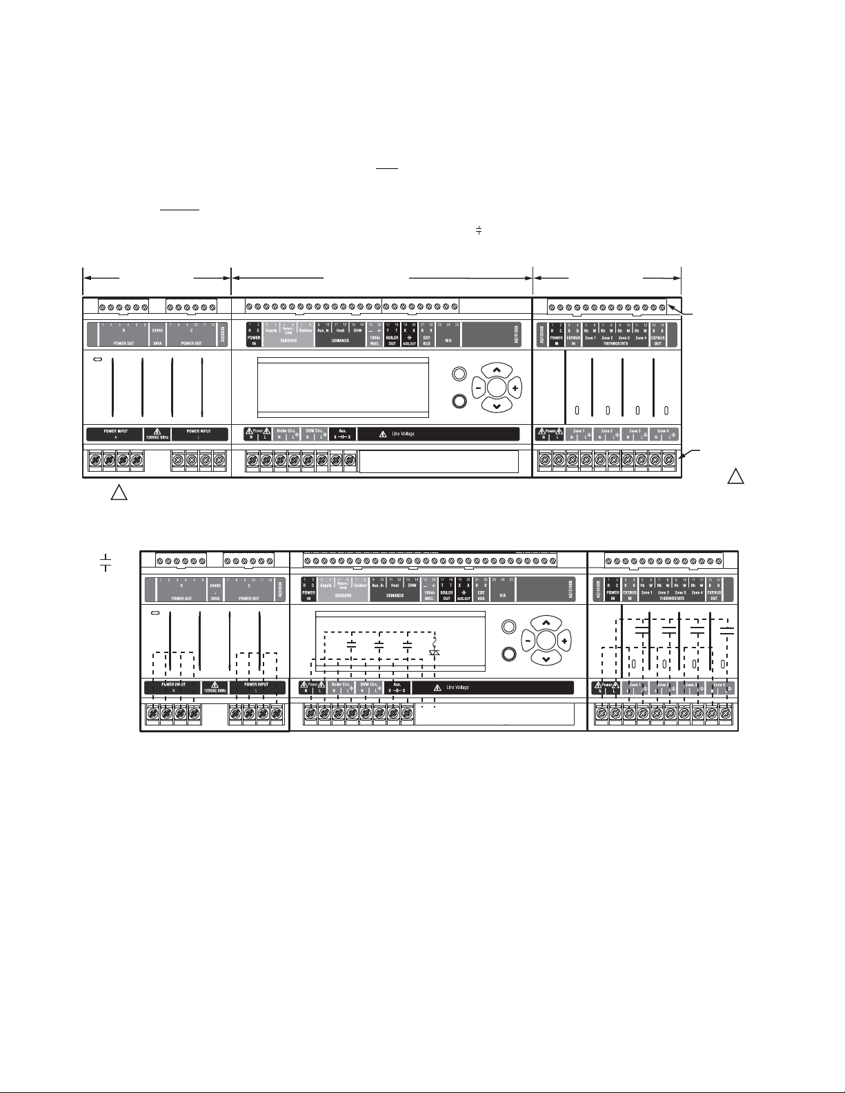
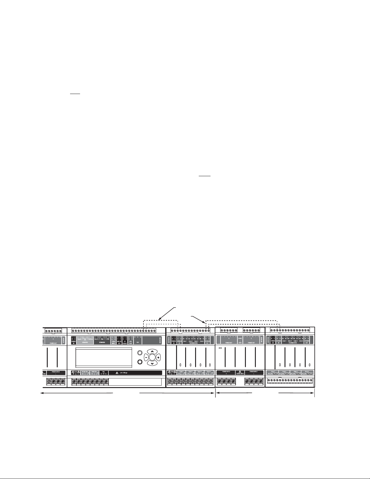
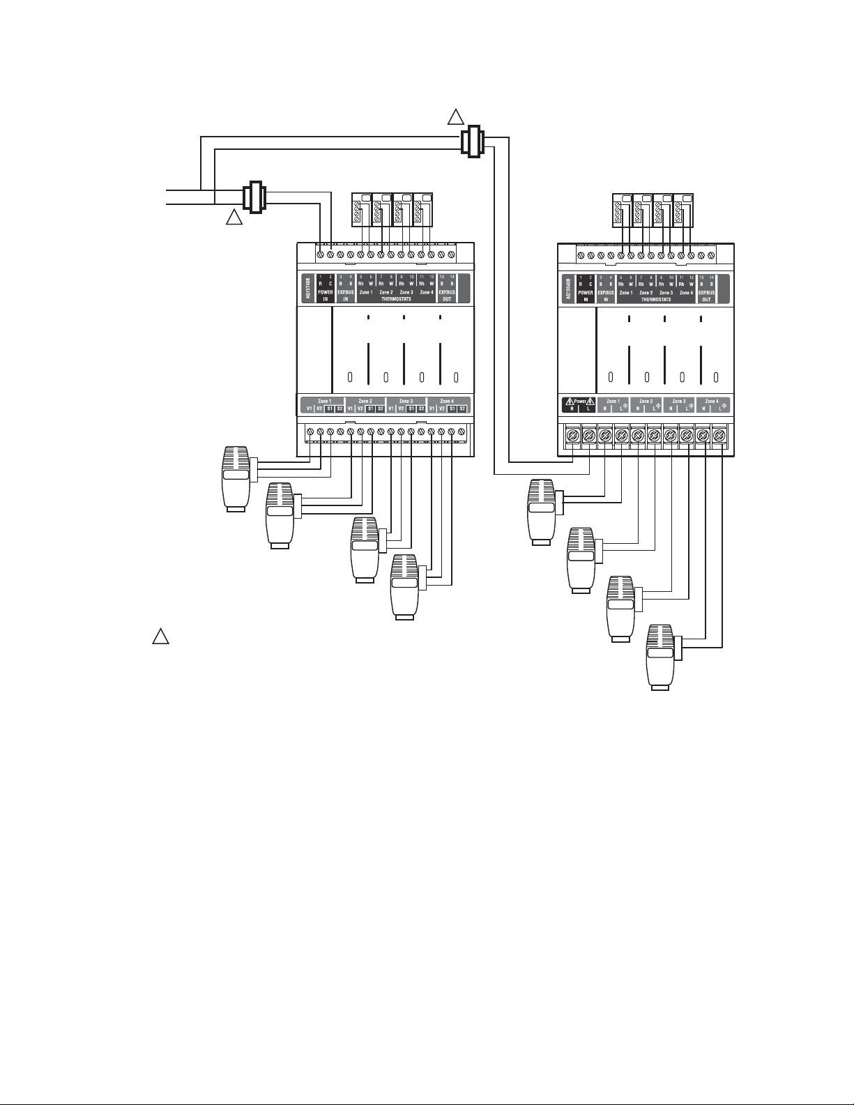
In general, the top terminals of the AQ2000 Series components
carry low voltage (24 Vac) powe r and the bottom terminals
carry line voltage (120 Vac) power. This is illustrated in Fig. 1.
The two exceptions to this are:
1. AQ15740B Zoning Module for use with zone valves with
end switches.
2. AQ15540B Zoning Module when used with low voltage
zone valves without
end switches.
For these the two exceptions, the bottom terminals of the
Transformer and Control Module carry line voltage (120 Vac),
but the bottom terminals of the Zoning Module will carry low
voltage (24 Vac) power.
The powered terminals on the bottom of the AQ2000 Series
Control Modules and Zoning Modules are connected internally
as shown in Fig. 2. The voltage supplied to the N and L
terminals is also available at the adjacent terminal pairs when
the hot ( ) relays are switched.
Fig. 1. AQ25A Series Programmable Boiler Control Panel layout (AQ25A42B shown).
Fig. 2. Internal wiring for AQ2000 Series components line voltage relays.
69-2119—05 4
Page 5
AQ25A SERIES PROGRAMMABLE BOILER CONTROL PANELS
2MOUNTING
This section describes how to mount the Control Panel,
Expansion Zoning Panels, and the Thermostats.
Mount AQ25A Control Panel
Mount the control panel on the wall:
1. Use the template supplied with the AQ25A Series
Programmable Boiler Control Panel to mark mounting
holes for panels.
2. Install two top screws, mount the panel, and install the
two lower screws.
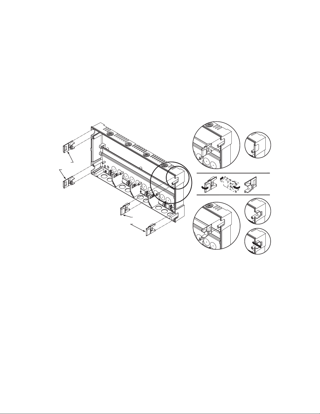
WIRE
CHANNEL
PLUGS
Mount Expansion Zoning Panel(s)
If there are Expansion Zoning Panels to install, they should be
mounted on the wall now.
1. Remove wire channel plugs from the AQ25A Control
Panel and any Expansion Panels (see Fig. 3).
2. Mount Expansion Zoning Panel on the right-hand end of
the AQ25A Control Panel. Install two top screws of the
Expansion Zoning Panel, ensuring it is level with the
adjoining Control Panel, and install two lower screws.
3. Reverse wire channel plugs and re-insert them into their
slot to from a wiring channel between the Control Panel
and the Expansion Zoning Panel (see Fig. 3) and to
connect the two panels together.
4. Repeat steps 1–3 for any additional Expansion Zoning
Panels.
WIRE
CHANNEL
PLUGS
Fig. 3. Orientation of wire channel plugs for creating pass-through wire channel and
for joining Control Panel to Expansion Zoning Panels.
Mount and Wire Thermostats in the Zones
Install the thermostats on the walls in the zones that are to be
controlled by the AQ251 Control Panel.
When using AQ1000 thermostats, refer to the installation
instructions included with the AQ1000 thermostats.
If not done already, run low voltage thermostat wire (24 gauge
or heavier) from the thermostats back to the AQ25A Control
Panel.
NOTE: If not otherwise specified, low voltage wiring should
be run with 18 gauge thermostat wire and line voltage
wiring should be run with 14 gauge wire. AQUATROL
line voltage screw terminals are approved for use with
22 to 12 gauge copper conductors.
Several wiring diagrams are included in this
document. For additional information, refer to
http://customer.honeywell.com or your local
distributor.
M23733A
3 WIRING PROCEDURE
The AQ25A Control Panel is pre-wired at the factory, making
for faster installation.
For all models, the low voltage output terminals located at the
top of the transformer secondary are wired to the R and C input
terminals of the Control Module, as well as the R and C inputs
of the Zoning Module. The B-B Exp. Bus terminals (21 and 22)
of the Control Module are wired to the B-B Exp. Bus IN
terminals of the Zoning Module.
Beginning with the top left of Fig. 4 on page 6 and moving
clockwise around the panel, wire components to the AQ25A
Control Panel and Expansion Zoning Panels (if installed) in the
following six steps:
• “Step 1 – Transformer Wiring” on page 6
• “Step 2 – Con tro l Pan el Wi ri ng ” on page 6
• “Step 3 – Thermostats Wiring” on page 9
• “Step 4 – Zoning Equipment Wiring” on page 9
• “Step 5 – Line Voltage System Outputs” on page 12
• “Step 6 – Connection to Line Voltage Power” on page 13
5 69-2119—05
Page 6
AQ25A SERIES PROGRAMMABLE BOILER CONTROL PANELS
M27755A
Zone 1
Zone 2
Zone 3
Zone 4
STEP 1 STEP 2 STEP 3
STEP 4STEP 5STEP 6
TO EXPANSION ZONING MODULES
(IF INSTALLED)
Menu
Home
OK
M27756A
TO BOILER SUPPLY SENSOR
TO BOILER RETURN SENSOR
TO OUTDOOR SENSOR
IN FROM “R” TERMINAL ON
TRANSFORMER MODULE
(FACTORY-WIRED)
TO “T-T” TERMINALS ON
BOILER AQUASTAT
TO B-B “EXP.BUS IN”
TERMINALS ON CONNECTED
ZONING MODULE
TO SETPOINT LOAD
(OPTIONAL)
TO DHW AQUASTAT
IN FROM “C” TERMINAL
ON TRANSFORMER MODULE
(FACTORY-WIRED)
TO LOW VOLTAGE AUXILIARY
DEVICE (OPTIONAL)
TO AUXILIARY INPUT
SWITCH (OPTIONAL)
TO MODULATING INPUT
ON BOILER
Fig. 4. Wiring sequence.
Step 1 – Transformer Wiring
Factory pre-wiring of the Control Panels is shown as dotted
lines in Fig. 4.
Step 2 – Control Panel Wiring
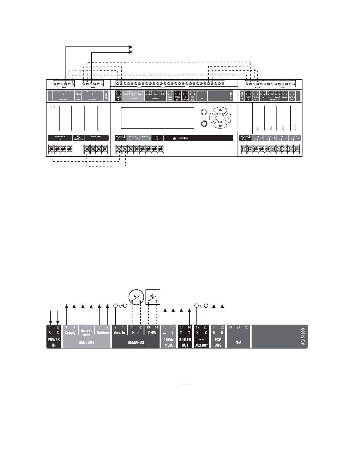
Wire the Temperature Sensors, System Demands, Low
Voltage Outputs, and Communication Bus (Refer to Fig. 5 for
wiring terminals on the top of the AQ25A):
In addition to the pre-wiring, run low voltage jumper wires from
available R and C terminals to the R and C terminals of any
Expansion Zoning Panel.
• “Temperature Sensor Wiring”
• “System Demands Wiring” on page 7
• “Low Voltage Outputs Wiring” on page 8
• “Communication Bus Wiring” on page 8
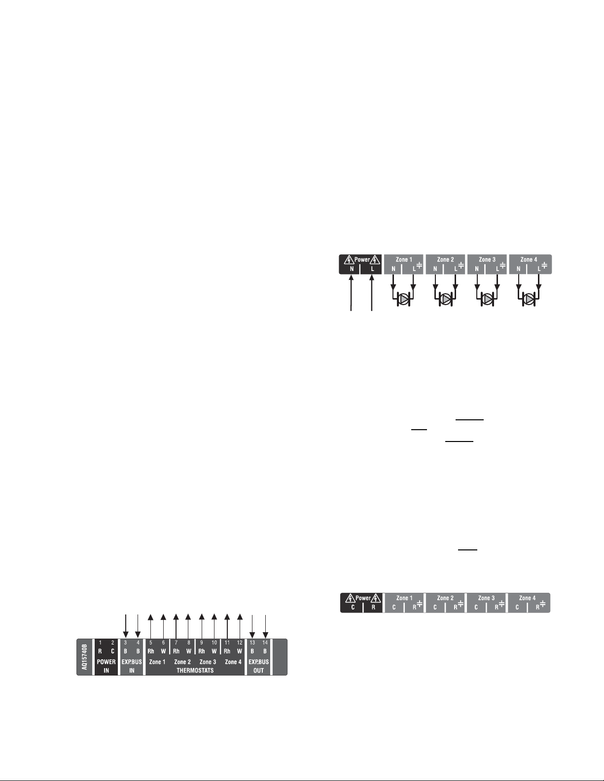
Fig. 5. Low voltage wiring for the AQ15A10B Control Module.
Temperature Sensor Wiring
Connect the lead wires of each sensor to the corresponding
terminals on top of the AQ15A Control Module. See Fig. 5.
The Boiler Supply and Return sensors can be installed either
as strap-on sensors or inserted into an immersion well that is
packed with thermally conductive paste.
BOILER SUPPLY AND RETURN SENSORS.
Both
the Supply and Return Sensors should be installed on the
supply and return piping of the boiler for proper operation of
the AQ25A Control Panel. Even if the AQ25A is connected to a
modulating condensing boiler with its own supply and/or return
sensors, the AQ25A’s sensors should still be installed for the
control to operate.
The Boiler Supply water sensor should be installed on the
supply piping close to the exit port of the boiler, using one of
the AQ12C11 strap-on sensors supplied with the AQ25A (see
Fig. 6 on page 7).
69-2119—05 6
Page 7
The Boiler Return sensor should be installed on the return
M13763
M13775
piping as close to the entrance port to the boiler as practical,
using the other AQ12C11 strap-on sensor supplied with the
AQ25A.
The correct location is one that will measure the temperature of
all combined sources of water returning back to the boiler.
Insulate strap-on sensors with pipe wrap to ensure accurate
boiler temperature sensing.
The Boiler Supply and Return water sensors come with 10 ft.
(3m) of wire to minimize the need for splicing.
AQ25A SERIES PROGRAMMABLE BOILER CONTROL PANELS
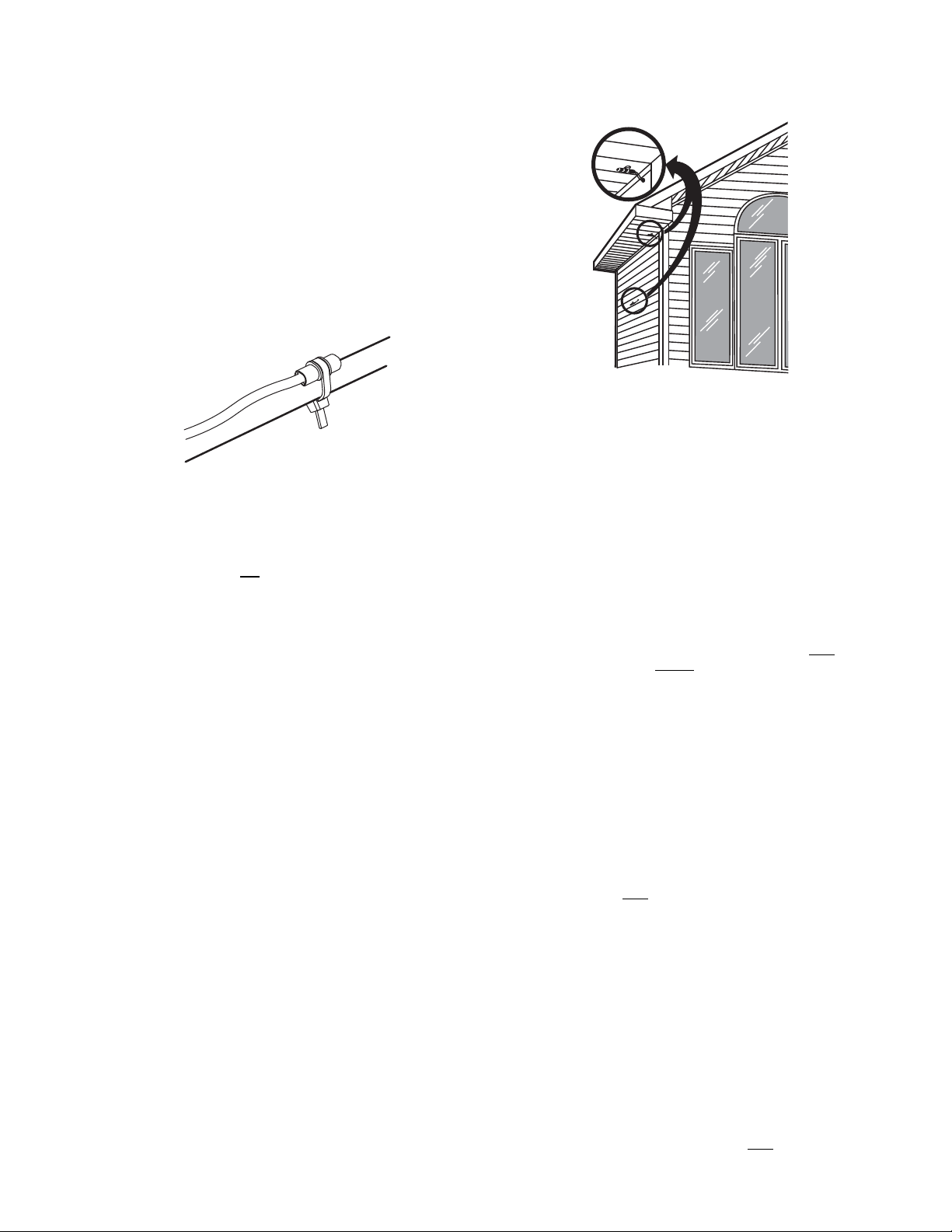
Fig. 7. Outdoor temperature sensor installation.
Fig. 6. Strap-on temperature sensor installation.
OUTDOOR SENSOR: FOR USE WITH AQ1000 THERMOSTATS
IMPORTANT
The AQ25A is not
an Outdoor Reset Boiler Control
Panel. The purpose of the outdoor sensor is to
communicate the outdoor temperature to the
AQUATROL network for display on all AQ1000
thermostats.
The outdoor sensor should be located:
• in a shady location out of direct sunlight
• at least three feet from dryer, bathroom, or other vents
• above the expected snow line where ice and debris
cannot cover it
• on the North side of the building.
See Fig. 7 for typical placement. Outdoor sensor comes with
10 ft. (3 m) of wire to facilitate splicing the sensor on the interior
of the building. Alternatively, if the building is equipped with a
continuous fresh air supply using, for example, an air-to-air
heat exchanger, the outdoor sensor may be installed in the
insulated portion of the ventilation intake duct, taking care not
to expose the sensor to direct or indirect sunlight.
IMPORTANT
Do not run sensor wires parallel, or close, to
telephone, Ethernet, or power cables. Cross all
power, Ethernet, and telephone wiring at right angles.
If sensor wires are located in an area with strong
sources of electromagnetic interference, or EMI, (e.g.,
if sensor wires are run in the same electrical chase as
line voltage wiring) use twisted pair, shielded cable, or
run wires in a grounded metal conduit. This is
important, since the calculated temperature - based
on the sensor's resistance reading - can be distorted
by high EMI, potentially causing the AQ25A to not
operate properly. If using shielded cable or conduit,
connect the shield wire to earth ground only
AQ25A panel. do not
ground the shield or conduit at
at the
any other location or electromagnetic shielding will be
ineffective. If shielded cable is used, Honeywell
recommends the use of shielded cable with a
continuous ground plane, such as foil, with an integral
drain wire for bonding to earth ground.
System Demands Wiring
Additional information about settings for the various System
Demands is discussed in Table 6 on page 30.
AUX-IN
If the optional Aux In. contacts (terminals 9 and 10) will be
used, wire them now. These inputs are powered with 24 Vdc
and must connect only
switch).
to a dry closure contact (unpowered
The Aux-In contact closure sets the system into a specific state
as determined by the installer setup using the EQUIPMENT
SETUP > AUXILIARY I/O sub-menu (see Fig. 25 on page 38).
HEAT DEMAND
If the optional Heat Demand (terminals 11 and 12) will be used,
wire them to a system setpoint demand (dry contact closure),
such as a pool or spa Aquastat®.
The HEAT contact closure drives the system to control either at
the Reset temperature or the Setpoint temperature as
determined by the installer setup using the EQUIPMENT
SETUP > ZONING > HEAT DMND selection (see Fig. 25 on
page 38). Heat Demand priority allows only
7 69-2119—05
heat for the first 30
Page 8
AQ25A SERIES PROGRAMMABLE BOILER CONTROL PANELS
minutes of a call for heat and then allows the space heati ng
needs to be added in for the next 30 minutes. This cycle
continues until the call for heat is satisfied.
DOMESTIC HOT WATER
Wire the DHW (terminals 13 and 14) to the Aquastat or
thermostat on the domestic hot water tank.
DHW priority allows only
DHW heat for the first 30 minutes of a
call for DHW and then allows the space heating needs to be
added in for the next 30 minutes. This cycle continues until the
call for DHW is satisfied.
NOTE: If the AQ25A is connected to a modulating
condensing boiler with built-in DHW management, the
DHW tank’s Aquastat should be connected to the
AQ25A's DHW (terminals 13 and 14). The AQ25A's
Aux. Out (terminals 19 and 20) should be wired to the
boiler's DHW input terminals to the AQ25A.
Low Voltage Outputs Wiring
10 VDC
The 10 Vdc terminals (15 and 16) of the AQ25A produce a
modulating (0-10 Vdc or 2-10 Vdc) signal that can drive a
modulating boiler’s combustion fan to maintain a constant
supply temperature from the boiler (generally equal to the
Boiler High Limit setting in the EQUIPMENT SETUP > BOILER
SETTINGS sub-menu).
Boiler Signal: If the AQ25A panel is configured to send a
0-10V or 2-10V signal to a modulating/condensing
boiler, connect the AQ25A ’ s modulating output terminals
(15 and 16) to the modulating signal input on the boiler
control.
These contacts are made any time the system has a request
for boiler operation, unless the water supply temperature is
above the target temp at that time, at which time the system
primary boiler pump would come on.
AUX-OUT
If the Auxiliary Out low voltage output will be used, wire it now
to the device that will be switched when the Auxiliary Out’s dry
contacts close. Wire the hot leg of the device through the Aux.
Out connection (terminals 19 and 20).
The Aux-Out relay contacts close to correspond with an action
as determined by the installer setup using the EQUIPMENT
SETUP > AUXILIARY I/O sub-menu (see Fig. 25 on page 38).
NOTE: The Aux. Out contacts are rated for low voltage
devices only.
Communication Bus Wiring
All AQ2000 components communicate with each other on the
AQUATROL network using communication bus wiring. This
wiring must
features that depend on this networked communication (e.g.,
zone synchronization, outdoor temperature displayed on
thermostats, etc.) will not function.
The communication bus wiring is polarity insensitive. The
installer does not need to worry about a +ve or –ve orientation
of the wires. If there are two wires connected between the B-B
Bus Exp. In on one module and B-B Bus Exp. Out on another
module, there will be communication. See example in Fig. 8 for
how this wiring is to be installed.
The communication bus connections are pre-wired at the
factory for AQ25A Control Panels.
connect all AQ2000 components. Otherwise
BOILER
Wire the Boiler dry contact output (terminals 17 and 18) to the
T-T terminals on the boiler Aquastat or the boiler's control
panel. See Fig. 15 on page 12 for wiring connections to a
typical boiler Aquastat.
Menu
OK
Home
AQ25242B
Fig. 8. Wiring for communication bus.
DATA BUS
COMMUNICATION
WIRING
Zone 1
Zone 3
Zone 2
Zone 4
AQ25744B
Zone 1
Zone 2
Zone 3
M27757A
Zone 4
69-2119—05 8
Page 9
AQ25A SERIES PROGRAMMABLE BOILER CONTROL PANELS
FROM B-B “EXP. BUS”
TERMINALS ON
CONTROL MODULE
TO B-B “EXP. BUS IN” TERMINALS
ON CONNECTED ZONING MODULE
(IF AN EXPANSION ZONING PANEL
IS CONNECTED)
THERMOSTAT ON ZONE 1
THERMOSTAT ON ZONE 2
THERMOSTAT ON ZONE 3
THERMOSTAT ON ZONE 4
M13776C
A
M27688A
Step 3 – Thermostats Wiring
NOTE: The new AQ2000 panels will work with digital (elec-
tronic) non-communicating thermostats. AQ1000
thermostats are not required.
WHEN USING AQ1000 THERMOSTATS:
1. Using low voltage thermostat wire, connect one AQ1000
communicating thermostat from each zone to the
corresponding TH inputs on top of the Zoning Module
(see Fig. 9 on page 9).
2. If there are additional zones (on Expansion Zoning
Panels) connected to this Zoning Module, run low
voltage thermostat wiring from the B-B Exp. Bus Out
connection (terminals 13 and 14) of the Zoning Module
to the B-B Exp. Bus. In connection (terminals 3 and 4) on
the Expansion Zoning Panel.
IMPORTANT
Do not run thermostat wires parallel, or close, to
telephone, Ethernet, or power cables. Cross all
power, Ethernet, and telephone wiring at right angles.
If thermostat wires are located in an area with strong
sources of electromagnetic interference, or EMI, (e.g.,
if thermostat wires are run in the same electrical
chase as line voltage wiring) use twisted pair,
shielded cable, or run wires in a grounded metal
conduit.
This is important because the AQ1000 thermostats
are communicating thermostats which send and
received data via the two wires connecting them to
the Zoning Module. This data can be distorted by the
EMI, potentially causing the AQ25A to not operate
properly.
3. Run low voltage thermostat wiring from the R and C
terminals on the AQ25A Control Panel’s transformer to
the R and C terminals on the Expansion Zoning Panel.
As an alternative, you can run low voltage thermostat
wiring from the R and C terminals on the Zoning Module
to the R and C terminals on the Expansion Zoning Panel.
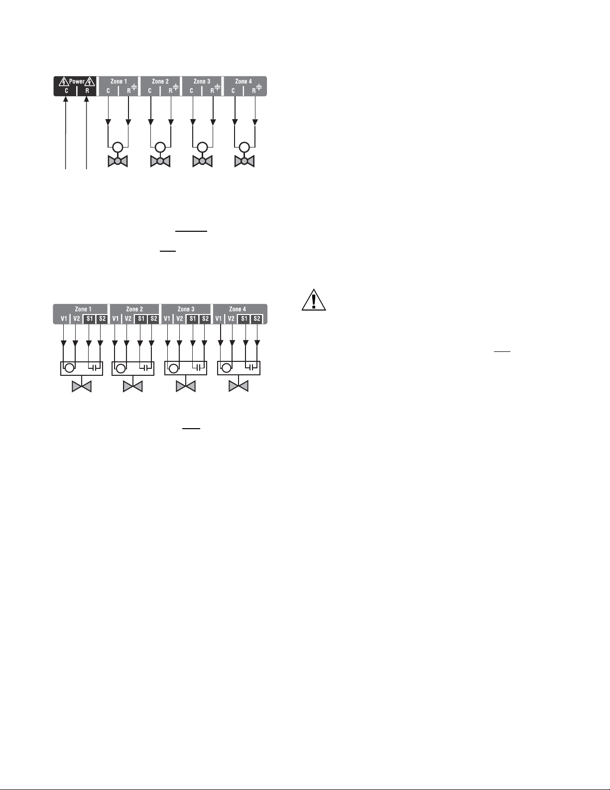
Step 4 – Zoning Equipment Wiring
Because the Zoning Module of the AQ25A Control Panel can
be used with either line voltage pumps or valves, or low voltage
zone valves (with or without end switches), field installed wiring
of the correct voltage needs to be connected to the zoning
equipment terminals on the bottom left portion of the Zoning
Module.
Line Voltage – Circulators or Zone Valves
Refer to Fig. 10. Remove the plastic wiring barrier that is
located in the bottom wiring channel between the AQ15A
Control Module and the Zoning Module. Run jumper wires from
the N and L terminals on the bottom of the AQ25A Control
Panel’s transformer, through the wiring channel across the
bottom of the Control Panel, and to the corresponding N and L
terminals of the Zoning Module.
FROM LINE VOLTAGE
120V TERMINALS
(N AND L) ON BOTTOM
OF TRANSFORMER
Fig. 10. Wiring an AQ15540B Zoning Module for use
with line voltage circulators.
Low Voltage – Zone Valves With or Without End
Switches
Wire using step 1 for zone valves without end switches or use
step 2 for zone valves with
1. Low voltage zone valves without
Using Fig. 12 as a guide, run jumper wires from the R
and C terminals on the top left of the AQ25A’s
transformer through the wiring channel across the top of
the Control Panel, down through the wiring channel on
the right side of the panel and over to the R and C
terminals on the bottom of the Zoning Module
end switches:
end switches:
M27687
Fig. 9. Connecting AQ1000 thermostats.
IMPORTANT
If low voltage zone valves are used with the AQ25A
Control Panel, the supplied Low Voltage Output
sticker (shown in Fig. 11) must
be applied over the
line voltage output sticker (see Fig. 10) that is already
attached to the Zoning Module.
Fig. 11. Low voltage output sticker.
9 69-2119—05
Page 10
AQ25A SERIES PROGRAMMABLE BOILER CONTROL PANELS
CAUTION
FROM LOW VOLTAGE
24 VAC TERMINALS
(C AND R) ON TOP
OF TRANSFORMER
M M M M
M27689A
Fig. 12. Wiring an AQ15540B Zoning Module for use
with low voltage zone valves without
end switches.
2. Low voltage zone valves with end switches:
See Fig. 13 on page 10. 24 Vac power is pre-wired
between the transformer secondary at the top left of the
AQ25A’s transformer and the AQ15740B Zoning
Module. No field wiring is required.
M
M
M
M
M27690A
Fig. 13. Wiring an AQ15740B Zoning Module for use
with low voltage zone valves with
end switches.
NOTE: When wiring zone valves with end switches, note the
transformer's VA:
If low voltage zone valves with end switches are used
for zone control, make sure the selected zone valves
do not draw more power (VA) than the 38 VA capacity
of the AQ10X38 transformer supplied with the AQ25A
Control Panel. This integral transformer has enough
power to operate 4 motorized zone valves (such as
Honeywell V8043E valves or 4 valves using lowamperage draw, heat motor actuators such as
Honeywell MV100 actuators), plus power the
electronics of the AQ25A's Control Module and up to
16 AQ1000 thermostats.
If zone valves with high-amperage draw, heat motor
actuators are used, such as Taco 500 series zone
valves, additional 24 Vac transformer capacity will
need to be wired to the Zoning Module to power the
valves. See Fig. 14 on page 11 for recommended
wiring of additional low voltage VA capacity to
AQ2000 Series Zoning Modules.
Equipment Damage Hazard.
Can damage internal circuitry of Zoning Module.
The ES1 and ES2 terminals of the AQ15740B Zoning
Module are powered terminals and must only
be
connected to a set of dry contacts, such as a zone
valve motor's end switch. If power is applied to these
contacts (for example, by running line voltage through
the zone valves’ end switches to bring on a circulator
feeding those valves), the internal circuitry of the
Zoning Module will be damaged, in which case the
warranty for this product will be voided.
69-2119—05 10
Page 11
AQ25A SERIES PROGRAMMABLE BOILER CONTROL PANELS
THERMOSTATS
ZONE 1 ZONE 2 ZONE 3
ZONE 4
M27691
THERMOSTATS
ZONE 1 ZONE 2 ZONE 3
ZONE 4
Zone 1
Zone 2
Zone 3
Zone 4
USING AN AQ15740B
VALVE ZONING MODULE
POWER SUPPLY. PROVIDE DISCONNECT MEANS AND OVERLOAD PROTECTION AS REQUIRED.
1
Zone 1
Zone 2
Zone 3
Zone 4
1
2
3
1
2
3
1
2
3
1
2
3
1
2
3
1
2
3
1
2
3
1
2
3
24 VAC
100 VA
TRANSFORMER
115 VAC
115 VAC
24 VAC
100 VA
TRANSFORMER
1
1
USING AN AQ15540B
PUMP ZONING MODULE
Fig. 14. Wiring of additional low voltage VA capacity.
11 69-2119—05
Page 12
AQ25A SERIES PROGRAMMABLE BOILER CONTROL PANELS
ZC
ZR
B1
B2
C1C2
L1L2
T
T
G
L8148, L7148
R8184A, R7184
BURNER AND
IGNITION
C554
F
F
T
T
BLACK
WHITE
ORANGE
POWER SUPPLY. PROVIDE DISCONNECT MEANS AND OVERLOAD PROTECTION AS REQUIRED.
L1
(HOT)
L2
1
1
TO AUXILIARY DEVICE
(INSTALLER-DEFINED)
BOILER
PUMP
M27763A
N
L
TO LINE VOLTAGE 120V
TERMINALS (N AND L) ON
BOTTOM OF TRANSFORMER
FROM LINE VOLTAGE 120V
TERMINALS (N AND L) ON
BOTTOM OF TRANSFORMER
TO BOILER
TERMINALS 22-23
ON TOP OF AQ15200B
CONTROL MODULE
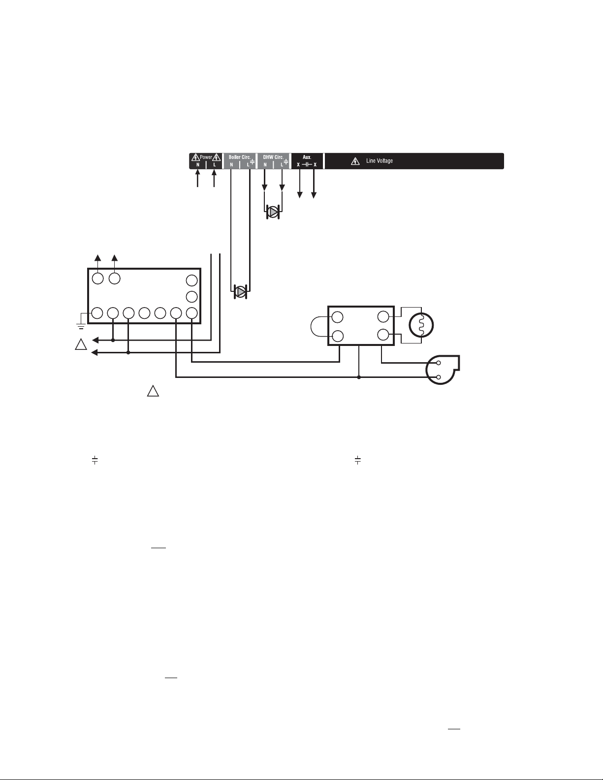
Step 5 – Line Voltage System Outputs
Refer to Fig. 15 and follow the steps in this section to wire
these devices to the AQ25A Control Module.
“1. Boiler Pump”
“2. DHW Device”
“3. Line Voltage Rated Aux Output (Aux. Pump)” on page 13
1. Boiler Pump
Connect the N and L wires of the boiler loop pump to the N and
switched hot ( ) terminals of the line voltage Boiler output,
shown in Fig. 17 on page 13. The ground wire of the pump can
be connected to any of the 8 ground screw terminals located
on the back surface of the Control Panel enclosure.
The boiler pump contacts are made after any one of the
following occur:
• A call for heat has occurred from any heating zone.
• The Heat input is shorted on terminals 11 and 12.
• The DHW input is shorted and
as a valve.
The pump is delayed for the FIRE DELAY programmed in the
EQUIPMENT SETUP > BOILER OPERATION sub-menu (see
Fig. 25 on page 38). The boiler pump and the last zone calling
remain on in order to move heat out of the boiler for the period
of time programmed in the Purge time menu under the fire
delay. Manually adjusting thermostats affects the operation of
this software so it can not be tested manually, you must
observe it under normal operating conditions.
NOTE: If the AQ25A is connected to a modulating
69-2119—05 12
Fig. 15. Line Voltage Connections for AQ25A.
the DHW type is configured
condensing boiler, the boiler pump may need to be
connected to the boiler, not
with the boiler’s installation manual.
the AQ25A. Confirm this
2. DHW Device
Wire the DHW pump or line voltage zone valve to the N and
switched hot ( ) terminals of the DHW output as shown in
Fig. 17 on page 13. If using a low voltage zone valve, wire the
primary of a spud-mounted transformer (115V to 24V) to the
DHW line voltage contacts and connect the low voltage zone
valve to the secondary terminals of this transformer. A spudmounted transformer may be located in one of the conduit
knockouts on the bottom of the AQ25A Control Panel.
Alternatively, a 24 Vac zone valve can be connected to the
Aux. pump line voltage-rated dry contacts which can be
configured to close on a DHW call. This configuration is
defined in the Installer Equipment Setup menu beginning on
page 30.
The DHW contacts are made when the DHW inputs on
terminals 13 and 14 are shorted by the controlling Aquastat.
This is a line voltage output designed to go to the DHW pump.
If 24 Vac is needed for a low voltage valve, you can mount a
step-down transformer on the conduit opening and wire the
valve from the transformer. When DHW is enabled, the system
has a 30 minute priority over all calls for heat. After 30 minutes,
calls for heat are added back in to the operation for 30 minutes
and then turned off again. This repeats until the DHW is
satisfied.
NOTE: If the AQ25A is connected to a modulating
condensing boiler, the DHW pump will probably need
to be connected to the boiler, not
this with the boiler’s installation manual.
the AQ25A. Confirm
Page 13

AQ25A SERIES PROGRAMMABLE BOILER CONTROL PANELS
TO AUXILIARY DEVICE
(INSTALLER-DEFINED)
FROM LINE VOLTAGE
120V TERMINALS
(N AND L) ON BOTTOM
OF TRANSFORMER
M27765A
AQ25A
Zone 1
Zone 2
Zone 3
Zone 4
Zone 1
Zone 2
Zone 3
Zone 4
Zone 1
Zone 2
Zone 3
Zone 4
M27766A
Menu
Home
OK
3. Line Voltage Rated Aux Output (Aux. Pump)
To connect a line voltage auxiliary device to these contacts,
such as a group pump or a boiler bypass pump, power the
pump from the N and L terminals on the bottom of the AQ15A
Control Module, running the L (hot) lead through the
AUX.Pump contacts. See Fig. 16 for details.
The Aux Pump is a line voltage rated dry contact that is
controlled by the selection in the EQUIPMENT SETUP >
AUXILIARY I/O sub-menu (see Fig. 25 on page 38).
BY-PASS PUMP
Fig. 16. Wiring of the Aux. pump line voltage rated dry contacts [example shown is for a by-pass pump].
NOTE: Use of this output is optional. The Aux. pump dry
contacts are line voltage-rated but unpowered. A low
voltage device can be connected to these
programmable contacts, but the wire's insulation must
meet applicable codes for use in line voltage
enclosures.
See page 30 for programming options for the Aux.
Pump dry contacts.
Wire the Installer-defined AUXiliary output to the line voltage
AUX terminals, as shown in Fig. 17. The exact wiring
schematic will depend on what is connected to these dry
contacts.
M27764A
Fig. 17. Wiring for Boiler Pump, DHW Device, and Aux Output.
Step 6 – Connection to Line Voltage Power
Connect the N and L line voltage inputs of the primary on the
AQ25A transformer to the electrical distribution panel and
power up the Control. A service switch should be installed on
the hot (L) lead to the distribution panel.
Fig. 18. Connections for multiple Zoning Panels - parallel wiring.
If multiple Zoning Modules are connected to the AQ25A
Control Panel, the line voltage wiring can either be run directly
from the N and L terminals on the transformer to each Zoning
Module (Fig. 18) or run in a daisy chain fashion from the N and
L terminals of one AQ2000 component to the N and L
terminals of the next AQ2000 (see Fig. 19 on page 14).
13 69-2119—05
Page 14

AQ25A SERIES PROGRAMMABLE BOILER CONTROL PANELS
CAUTION
Zone 1
Zone 2
Zone 3
Zone 4
Zone 1
Zone 2
Zone 3
Zone 4
Zone 1
Zone 2
Zone 3
Zone 4
M27767A
Menu
Home
OK
M23731A
AQ15540B
Fig. 19. Alternate Connections for multiple Zoning Panels - daisy chain wiring.
Electrical Shock or Equipment Damage Hazard.
Can shock individuals or short equipment circuitry.
When line voltage is applied to the AQ25A Control
Panel and the front cover of the Panel is removed,
there is a risk of electrocution. Be careful to avoid
contact with the line voltage (N and L) terminals, either
with your fingers or with metal tools (such as a
screwdriver) when power is applied to the Control
Panel.
4 PROGRAM AND CONFIGURE THE
CONTROL PANEL
Only two steps are required to set up the AQ25A Series
Control Panel:
1. Check the program settings for the Control Module:
Operation of the AQ25A's Control Module is set by the
menu selections accessible through the Control
Module’s LCD screen. See “AQ25A – System
Programming” on page 16 for instructions.
2. Check the DIP switch settings for each Zoning Module.
Control Panel Defaults
Operation of the AQ25A Control Module is set by the menu
selections accessible through the Control Module’s LCD
screen. See “AQ25A – System Programming” on page 16 for
instructions.
The AQ25A Control Panels are shipped from the factory with
pre-defined values for all program settings. These factory
default settings are commonly used by hydronics contractors
across North America. Usually, most of the settings only need
to be checked by the installing contractor to make sure they
are suitable for the job, rather than having to input all the
settings from scratch.
Although these factory default values for the Control Module
and each Zoning Module are suitable for many installations,
Honeywell recommends that they be reviewed, and changed
as necessary, to get optimal performance of the hydronic
system controlled by the AQ2000 Series products.
Zoning Module DIP Switch Location
The AQ15540B (pump Zoning Module) and AQ15740B (valves
with end switches Zoning Module) both have DIP switches in
8-switch banks and are concealed behind snap-on covers as
shown in Fig. 20.
Fig. 20. Location of Zoning Modules DIP switches.
Zoning Module DIP Switch Settings
A chart of the different sett ing s for each DIP switch is atta ched
to the inside of each DIP switch cover.
Refer to Table 2 on page 15, and check all DIP switch settings.
If necessary, change the switch settings to suit the desired
operation of the hydronic installation.
NOTES:
1. To set DIP switches 1 through 4, which identify the
unique address of each zone on the AQUATROL
network):
Refer to the descriptions in Table 2 for the correct
DIP switch settings for the Pump or Valve Zoning
Module.
Unpredictable zone behavior may occur if more
than one Zoning Module has DIP switches (1-4)
set to the same address.
2. DIP Switch 5 enables or disables Zone
Synchronization:
• The factory setting enables Zone Synchronization,
which is an energy saving feature of the AQ2000
panels. Zone Synchronization coordinates zone
demands to start at the same time when the boiler
cycle begins. The AQ2000 functions as activating
valves. The valve logic induces a delay before
activating the boiler pump even when zone pumps
are used. When Zone Synchronization is not
selected, the zone demands are served whenever
they call for heat.
69-2119—05 14
Page 15

AQ25A SERIES PROGRAMMABLE BOILER CONTROL PANELS
M23720A
AQ15540B
Test
Diagnostic
Test
M34972
ON
12345678
• The Zone Synchronization feature replaces the
pump/valve selection of previous AQ2000 versions.
When you finish setting the DIP switches for all the Zoning
Modules, replace the front cover of the AQ25A Control Panel
and the cover of each Expansion Zoning Panel.
Review the settings of all DIP switches for each Zoning Module
connected to an AQ15A, to ensure they are correct before
system start-up.
NOTE: The snap-on DIP switch covers are designed so they
cannot be removed (exposing the DIP switches)
when the front cover of the AQ25A Control Panel is in
place.
Table 2. AQ15540B Zoning Module (Pump Zoning Module) DIP Switch Arrangement.
DIP
Switch Switch Description Label and Factory Settings
1
Zone Address: The positions of these 4 DIP switches define the unique address for
2
each zone on the AQUATROL network. For each group of 4 zones, there can be only
3
one DIP switch in the right hand (ON) position.
4
The correct DIP switch settings for each zone module are:
• First Zone (1-4) Module: 1 = ON position; 2, 3, and 4 = OFF position
• Second Zone (5-8) Module: 2 = ON position; 1, 3, and 4 = OFF position
• Third Zone (9-12) Module: 3 = ON position; 1, 2, and 4 = OFF position
• Fourth Zone (13-16) Module: 4 = ON position; 1, 2, and 3 = OFF position
• If set to SYNC, zone synchronization is enabled.
5
• If set to NOT, zone synchronization is disabled.
• If zone valves are normally closed (N.C.), set the NC/NO DIP switch to the OFF
position.
• If zone valves are normally open (N.O.), set the NC/NO DIP switch to the ON
6
position.
• If set to Group (ON position), the AUX Pump contacts on the Control Module are
switched when any of the zones on this Zoning Module are active.
• If set to - (OFF position), the AUX Pump contacts are not affe cted by activity on
7
these zones.
• If set to 2-stage (ON position), then 2-stage operation is activated on thermostat
inputs. The zoning module operates as two 2-stage zones.
8
• If set to 1-stage (OFF position), then operates as four 1-stage zones.
15 69-2119—05
Page 16

AQ25A SERIES PROGRAMMABLE BOILER CONTROL PANELS
M23538
ARROW INDICATES
THE CURRENTLY SELECTED
“ACTIVE” MENU ITEM.
M27698
UP ARROW, IF DISPLAYED,
INDICATES THAT OTHER MENU
ITEMS EXIST ABOVE AND CAN
BE VIEWED BY SCROLLING
UP WITH THE BUTTON.
DOWN ARROW, IF DISPLAYED,
INDICATES THAT OTHER MENU ITEMS
EXIST BELOW AND CAN BE VIEWED
BY SCROLLING DOWN WITH
THE BUTTON.
GRAPHIC SHOWING THE DEGREE OF
MIXING IN THE SECONDARY LOOP:
# OF BARS INCREASES AS A) THE
INJECTION PUMP SPEED INCREASES,
B) THE VOLTAGE OF THE MODULATING
VALVE SIGNAL INCREASES OR C) THE
ACTUAL MIX TEMPERATURE APPROACHES
THE MAXIMUM MIX TEMPERATURE
:
STATUS OF SYSTEM DEMANDS
- CALL FOR HEAT
- CALL FOR DHW
- SIGNAL ON AUXILIARY INPUT
STATUS OF SYSTEM OUTPUTS
- AUXILIARY OUTPUT ACTIVE
- BOILER T-T OUTPUT ACTIVE
DISPLAY AREA SHOWING
SYSTEM STATUS AND MENU
OPTIONS AND SELECTIONS
MADE
STATUS OF LINE VOLTAGE OUTPUTS
- PRIMARY (BOILER) HEAT
- DHW PUMP
- SECONDARY PUMP
- AUXILIARY “PUMP” OUTPUT
GRAPHIC SHOWING
THE PERCENTAGE
OF THE BOILER’S
HEATING CAPACITY
AT WHICH IT’S
OPERATING; ARROWS
ABOVE AND BELOW
THE BAR SHOW THE
TREND OF THE
BOILER’S
TEMPERATURE
(UP OR DOWN)
:
AQ25A – System Programming
This section describes how to navigate the user interface using
the keypad and LCD display, and how to program the AQ25A
Control Panel, which begins on page 17.
Keypad
The AQ25A User Interface consists of an LCD screen (16
characters by 3 rows) and a 7-button keypad for navigating the
menus, as illustrated in Fig. 22. Fig. 21 provides an isolated
view of the keypad.
Fig. 21. AQ25A keypad.
Menu Press this button to access the User Menu. When
pressed while in a sub-menu, the sub-menu’s
values are saved before going up one level in the
current menu.
Home Press this button to leave the User or Installer Menu
and return to the Home Page display screen.
OK Press this button to enter a sub-menu of the active
menu item. A menu item is active when the indicator
arrow is positioned beside the item.
and v Press these buttons to scroll up/down in the menu
^
items. Pressing one of these buttons automatically
saves your current selection, exits the edit mode,
and moves to the previous or next menu item.
– and + Press these buttons to decrease/increase the value
of a selected menu item, or to scroll through a list of
pre-defined options.
- If the menu item being modified is a number, the
displayed value will decrease/increase by pressing
these buttons. When holding the – or + button for
more than a second, the values automatically
decrease/increase at a faster pace, similar to setting
the time on a digital clock radio
.
- If the menu item is an option, pressing these
buttons scrolls through the list of available options
one at a time.
LCD Display
The LCD on the AQ25A Control Panel is used to:
— Monitor system status and performance.
— Select and/or modify control settings for the hydronic
system.
— Diagnose and troubleshoot system problems.
The layout of the display is logical and simple to navigate. The
information displays so that the installer can see at a glance
the system’s operating temperatures as well as the status of
the system equipment such as a Call for heat, DHW pump On,
Boiler T-T terminals energized, etc. In addition, all system
information displays in simple, straightforward English for quick
system diagnosis. Fig. 22 illustrates the layout and features of
the LCD display panel and keypad.
69-2119—05 16
Fig. 22. LCD display and keypad layout.
Page 17

AQ25A SERIES PROGRAMMABLE BOILER CONTROL PANELS
LCD Display Navigation
This section describes how the keypad is used to navigate the
LCD display and menus.
• The LCD displays up to three lines of text at a time. For
menus with more than three lines, use the up and down
buttons (
• As the menu is scrolled up or down, the indicator arrow
shows which menu item is active.
• If the active menu item is part of a list of predefined options
(e.g., Day of the Week) press the – or + button to scroll
through the available options until the preferred option is
displayed. The option is automatically saved when the
indicator arrow is scrolled away from the value being edited.
• If the active menu item requires you to define a value (e.g.,
a setpoint), use the – or + button to decrease or increase
the value until the desired value is displayed. The selection
will be saved when the indicator arrow is scrolled up or
down.
NOTES:
• If the active menu item leads to a further sub-menu,
pressing the OK button displays the sub-menu options on
the LCD. Scroll through this sub-menu to position the
indicator arrow beside the desired menu item to input or
modify. Choose one of the options provided or input the
desired value for the menu item. When satisfied, scroll to
another item and your selection will be saved.
• To define or modify another item within the same menu,
scroll the up and down buttons (
arrow is beside the desired option. Use the – or +
buttons to set the value for that item.
• To move back (up) one level within a menu, press the Menu
button.
• T o return to the Home Page display , press the Home button.
or v) to scroll through the menu options.
^
1. When setting times for the setback schedule, you
must
2. The OK button, when pressed, defaults the time
use the – or + button to change the time.
setting to “--:--” (midnight).
or v) until the indicator
^
NOTES: Home Page display upon restart after a power failure
of more than four hours:
1. Upon restarting the AQ25A following a power disruption of greater than 4 hours, the message PLS
SET DAY/TIM E OF DAY displays on the top line of
the Home Page screen. The message disappears
after the DAY and TIME OF DAY are updated.
— If the power failure parameter is set to Back-
light (USER MENU > PREFERENCES), the
LCD backlight flashes repeatedly, along with
the message.
2. The AQ25A starts up with its clock settings as:
DAY = MONDAY, TIME OF DAY = 12:00 midnight,
and program = OCCupied.
3. Until the DAY and TIME OF DAY settings are
adjusted, the control remains in permanent
setpoint (comfort) mode.
4. When the DAY and TIME OF DAY settings are
adjusted, the AQ25A follows the four programs of
WAKE, LEAVE, RETRN (return), and SLEEP.
Refer to “Home Page” on page 23 in the “Appendix” for
illustrations of the Simple and Detail displays.
Programming the AQ25A
Program the AQ25A by using the keypad and LCD display to
select parameters from the User and Installer menus. Refer to
to Fig. 22 on page 16 for an illustration of the LCD screen and
keypad.
NOTE: The figures in “Menu Structure” on page 37 provide a
graphical layout of the AQ25A’s User and Installer
menus.
When a new AQ2000 component is connected on the
AQUATROL network, it is seamlessly integrated in the system
after a few seconds. If one or more components are
disconnected or stop providing data to the network, a message
will appear on the System Status display until the fault is
corrected.
NOTE: The AQ25A automatically returns to the Home Page
display after 60 minutes of inactivity on the keypad.
HOME PAGE DISPLAY
The Home Page is the default view displayed on the AQ25A
Control Panel's LCD screen.
There are two Home Page views - Simple and Detail.
• Simple view shows 3 lines of text and is a brief description
of the system operation: Day , Time of Day, Current Program
and Outdoor temperature.
• Detail view includes the same 3 lines plus up to 10 lines of
additional information, including Boiler Supply and Return
temperatures, Secondary (Mixed loop) temperature, Boiler
Supply Target temperature, Secondary Loop Target
temperature, Zone Count, and DHW temperature (if
configured for DHW sensor use). Detail view is the factory
default setting for the Home Page.
The choice of the Simple or Detail Home Page view is made
from the USER MENU > PREFERENCES/TIME menu option.
The Home Page together with the System Status information
(a selection from the User Menu), provide a service contractor
extensive diagnostic information for troubleshooting the
installation.
17 69-2119—05
User Menu
The User Menu is intended for use by the building owner to
choose the LCD display preferences, Zone Settings (including
setpoint temperatures and setback times for each zone), and
temperatures for the WAKE, LEAVE, RETRN (return), and
SLEEP programs.
The Home Page and User Menu allow the building owner to:
• View the status of the system.
• Set up preferences for how the system information is
displayed.
• Set target temperatures for each zone.
• Program times of the day when the system will set back the
temperatures for all zones.
NOTE: If there are any problems with the system’s operation,
the AQ25A displays error codes on the System S t atus
Page display of the LCD panel. For details on these,
refer to “Troubleshooting” on page 20.
TO ACCESS THE USER MENU:
Press the Menu button on the keypad at any time to access the
User Menu.
Page 18

AQ25A SERIES PROGRAMMABLE BOILER CONTROL PANELS
Refer to Table 5 on page 24 in the “Appendix” for all of the
User Menu options for the AQ25A Control Panel, the factory
default values and permissible ranges for each option, and a
brief description of each setting.
Installer Menu
The Installer Menu is used to:
— Set up and modify the Equipment Settings (for boiler
operation, DHW management, zoning, auxiliary input/output
operation, and options such as pump/valve exercise, freeze
protection, and Save/Restore settings)
— Access the Test and Purge functions to facilitate quick and
simple commissioning of the hydronic system.
TO ACCESS THE INSTALLER MENU:
1. Press the Home button to return to the Home Page
display.
2. Press and hold the OK button for 3 seconds until the
message, INSTALLER MODE – ARE YOU SURE?,
displays.
3. Select YES.
4. Press and release the OK button to display the Installer
Menu.
Refer to Table 6 on page 30 in the “Appendix” for all of the
Installer Menu options for the Control Panel, the factory default
values and permissible ranges for each option, and a brief
description of how each setting affects the AQ25A’s operation.
5 TEST AND CHECK OUT THE
INSTALLATION
Startup
IMPORTANT
Apply power to the AQ25A Control Panel only after
of the AQ2000 SERIES components (Control Panel,
thermostats, sensors, Zoning Panels) have been
connected to the other equipment in the hydronic
heating system (boiler, zone valves or pumps, DHW,
Aquastat, etc.).
When powered, the AQ25A Control Panel begins its start-up
routine, establishing communication with all other AQ2000
Series components on the AQUATROL network.
Test
The TEST feature enables the installer to checkout all of the
system’s outputs, sensors, and zone equipment as part of
system commissioning (Checkout).
The TEST operation is accessed from the Installer Menu
option EQUIPMENT SETUP >TEST AND PURGE. To begin
testing the installation, position the indicator arrow beside
the equipment group to be tested (OUTPUTS, SENSORS, or
ZONES) and press the OK button.
TEST OUTPUTS
• When TEST OUTPUTS is selected, the AQ25A LCD
displays a list of all outputs that can be tested. To select an
output to test, position the indicator arrow beside that
output and press the + button to activate the output's relay.
As each output is activated, a word icon for that output is
all
displayed at the top or bottom of the LCD display (refer to
Fig. 22 on page 16). The test routine activates the output
relay until the “–” button is pressed to turn off that output.
• To test additional outputs, navigate the list using the up and
down arrows (
beside that output and press the + button to begin testing.
Press the “–” button to de-activate the output relay and stop
its test.
• Any combination of outputs can be activated at the same
time when testing the outputs.
• When finished testing the outputs, press the Menu button to
return to the TEST AND PURGE sub-menu.
TEST SENSORS
When TEST SENSORS is selected, the AQ25A LCD displays
the temperature that each of the SUPPLY, RETURN,
SECONDARY and OUTDOOR sensors is measuring. If a
sensor is malfunctioning or is not properly connected to the
AQUATROL network, the value “- -” displays beside that
sensor on the LCD, instead of its temperature. If any of the
sensors reports a temperature that is illogical, investigate
further by referring to “Troubleshooting” on page 20.
TEST ZONES
• When TEST ZONES is selected, the Installer can test all
space heating zones connected to the AQ25A
simultaneously or individually.
• If zones are tested simultaneously (TEST ALL ZONES), all
zone outputs energize immediately (with a delay of 1/10th of
a second between each pump or valve to minimize the
chance of electrical circuit overloads caused by the inrush
currents from the pumps’ motors).
• A zero (0) displayed after a zone’s ID address (e.g., Zone
A1 0, A2 0, A16 0) indicates that the AQ25A Control Module
has received confirmation that the zone’s pump or valve is
closed, or OFF. Similarly, a one (1) displayed after a zone’s
ID address (e.g., Zone A1 1, A2 1, A16 1) indicates that the
AQ25A has received confirmation that the zone’s pump or
valve is open, or ON.
• For zone pumps or zone valves without endswitches, a 1 is displayed as soon as the pump is
energized.
• For zone valves with end-switches, a 1 is displayed
only after the valve's end switch makes or the
valve's Time To Open delay has expired (for use
with 2-wire valves).
• To test zones individually, position the indicator arrow
beside a selected zone and press the + button to energize
it, and press the – button to de-energize it. As each zone is
tested, the Status LED on the Zoning Module associated
with that zone illuminates. T o test additional zones, position
the indicator arrow beside the zone to be tested, press
the “+” button to energize the zone’s pump or valve, and
then press the “–” button to de-energize it.
• Any combination of zones can be activated at the same
time when testing the zones.
• When finished testing the zones, press the MENU button to
return to the SETUP >TEST AND PURGE menu.
or v), position the indicator arrow
^
Checkout
1. From the Installer Menu, select Boiler Settings and
reduce the Warm Weather Shut Down (WWSD)
temperature setting until it is disabled and the display
shows “- -”. This way, the WWSD will not interfere with
the zone operation during checkout.
2. Turn down the DHW Aquastat, if present, to avoid
interfering with space heating control operation.
69-2119—05 18
Page 19

AQ25A SERIES PROGRAMMABLE BOILER CONTROL PANELS
3. Turn up the setpoint of one of the thermostats.
a. The zone valve or pump associated with that zone
turns on.
b. The Boiler T-T relay activates (Boiler displays in the
demands section of the LCD screen and the Boiler
pump relay activates (PRIMary displays in the
outputs section of the LCD screen).
NOTE: See Fig. 22 on page 16 for the demands and outputs
display areas on the LCD.
c. Depending on the settings for the AUX.PUMP (line
voltage rated dry contacts) and the AUX OUT (low
voltage rated dry contacts), either or both of these
relays may also close.
4. Turn down the set point of one thermostat. The zone
valve or pump associated with that zone should turn off.
The Boiler T-T and Boiler pump relay outputs should deactivate.
5. Repeat steps 3 and 4 for all zones to verify each zone is
operating correctly. Thermostats may be exercised
individually or all together to accelerate the check out
process.
6. Turn up the DHW Aquastat to simulate a call for hot
water.
a. If the DHW device is a pump, the DHW relay output
energizes immediately. The Boiler pump relay
remains off.
b. If the DHW device is a valve, the Boiler pump relay
energizes after a delay to allow the zone valve to
fully open. This delay is selected from the
EQUIPMENT SETUP>DHW>DHW VLV.OP menu
option.
c. Turn up the set point of one thermostat.
(1) If the DHW relay is configured to control a pump,
and DHW PRIOrity is selected, the Boiler and the
associated zone pump’s relay remain off.
(2) If the DHW relay is configured to control a valve,
and DHW PRIOrity is selected, the Boiler pump
activates after a delay for the DHW zone valve to
open, but the associated zone relays remain off.
(3) If DHW PRIOrity is disabled, space heating zone
pumps and valves should operate during a call for
DHW.
7. Turn down the DHW Aquastat to end the call for hot
water. Space heating operation should continue (if DHW
priority is disabled) or resume (if DHW PRIOrity is
enabled).
6 PURGE AIR FROM ALL SYSTEM
AND ZONE PIPING
The PURGE operation on the AQ25A Control Panel allows the
installer to purge all zones (loops) sequentially, or each zone
individually, for a period of time, PURGE TIME, which selected
from the EQUIPMENT SETUP>TEST AND PURGE>PURGE
sub-menu. The purge time can be adjusted in increments of 1
minute, up to a maximum of 30 minutes per loop to be purged.
After you have defined which loops to purge (all loops, or an
individual loop) and for how long (using the AQ25A’s menus),
position the indicator arrow beside the START PURGE
option and press the OK button. The START PURGE display
will change to STOP PURGE and the AQ25A display begins
counting down the time remaining for the purge cycle.
Purging All Loops
When the purge time has elapsed for the first loop, the control
proceeds to the next loop and performs the purge operation on
each loop in sequential order. After all selected loops have
been purged, the display shows PURGE COMPLETED.
7 DOCUMENT AND KEEP A RECORD
OF ALL SYSTEM SETTINGS
After the AQ25A Series Control Panel has been set up, and the
entire hydronic installation is operating properly, it is important
to document all the system settings for future reference.
Job Records
All AQ2000 Series Panels are shipped with Installation Job
Records for documenting these settings. These should be filled
out completely and saved in the Installing Contractor’s files.
NOTES: There are two classes of settings used by the AQ25A
to control the operation of the heating system, Zone
Settings and System (or Equipment) Settings. Both
types of settings are stored in non-volatile memory
and are not lost following an extended power
disruption.
WHEN USING AQ1000 THERMOSTATS
1. Zone Settings are designed to be adjustable by the
user or the installer and are stored in the faceplate
of each zone's AQ1000 thermostat. These settings
are not saved
the faceplates of two AQ1000 thermostats are
switched, the settings (setpoints, zone minimum,
zone maximum, etc.) will also be switched.
2. System Settings are designed to be adjustable
only
by the system installer and are stored in the
AQ15A Control Module. These are the settings
that are saved with the SAVE SETUP operation.
SAVE Feature
In addition to the hardcopy Installation Job Records, the
AQ25A Control Panel has a convenient SAVE feature that
allows the installing contractor to save the specific equipment
setting for this installation in the AQ25A’s memor y for future
recall, in case the system’s settings are inadvertently changed.
This feature is found in the EQUIPMENT SETUP >
SAVE/RESTORE sub-menu.
There are three levels of settings in the AQ25A’s memory –
CURRENT, FACTORY and SETUP.
• CURRENT settings are the settings that are currently
displayed in any of the menus and are the settings that the
AQ25A uses to operate. Any time a value is changed in any
of the menus, the CURRENT settings are changed and
these new settings are instantly used by the AQ25A Control
Panel.
• FACTORY settings are the default values loaded at the
factory and are the starting point for programming the
AQ25A. These values are permanently stored in memory
and cannot be over-written or erased. The AQ25A can be
restored to factory settings through the RESTORE
FACTORY option in the SAVE / RESTORE sub-menu. A
warning prompt, RESTORE FACTORY—ARE YOU
SURE?, displays and YES or NO must be chosen before
proceeding. If YES is selected, the FACTORY settings are
with the SAVE SETUP operation. If
19 69-2119—05
Page 20

AQ25A SERIES PROGRAMMABLE BOILER CONTROL PANELS
CAUTION
be copied to the AQ25A’s CURRENT settings and the
Control Panel begins to operate with these values
immediately.
• SETUP settings are the specific settings for this installation
which an installer has saved after the AQ25A is set up and
operating well. These are saved for future recall, in case the
system’s settings are inadvertently changed.
— T o save this installation's settings for the first time, go to
the EQUIPMENT SETUP > SAVE/RESTORE submenu. Position the indicator arrow beside SAVE
SETUP and press OK. This saves the current system
settings to the SETUP values.
— To retrieve the SETUP values at any time in the future,
go to the EQUIPMENT SETUP > SAVE/RESTORE
sub-menu and select RESTORE SETUP to load those
values into the AQ25A as the CURRENT settings. The
system will now operate according to these retrieved
settings.
— If the current settings are modified after a RESTORE
SETUP operation is performed, simply select SAVE
SETUP again to overwrite these new settings into the
SAVE settings memory.
If you change any system settings after a
RESTORE SETUP operation, you change the
current settings that the AQ25A uses as its basis of
operation.
TR OUBLESHOOTING
The following information helps the installer correctly identify
system problems, making troubleshooting much faster.
Table 3 and Table 4, beginning on page 21, describe the
possible error codes and status notices that can be
communicated on the AQ155 / AQ157 Zoning Modules'
diagnostic LEDs.
This diagnostic information is very valuable and the System
Status page is the first place a contractor should look for
information when troubleshooting system problems.
Communications Loss
Because all AQ2000 Series components communicate with
each other via the dedicated AQUATROL network when
controlling a hydronic system, one possible failure mode of the
AQ25A would be loss of communication between the AQ15A
Control Module and any connected Zoning Modules, or
between a Zoning Module and any zone thermostats
connected to the AQUATROL network. In general, the Control
Module:
• Periodically tries to re-establish communication with any
lost components on the network.
• Initializes any component that re-establishes its
communication.
• Displays an error code on the AQ25A’s System Status
page, until the error is corrected and/or communication is
re-established.
Control Module Reaction
When the AQ15A Control Module loses communication with
any number of zones for more than one minute (as long as
there’s still at least one zone communicating on the
AQUATROL network), the AQ25A continues to deliver heat to
the other non-communicating zones and the address of each
lost zone (e.g., A-7, B-4) displays on the System Status page.
When communication is lost with all
BOILER FREEZE PROTECTION mode, in which it fires the
boiler and then activates the Boiler (supply) pump and zone
equipment for a period of 10 minutes every hour. This should
provide sufficient heat to the system to prevent a building from
freezing up until communication is re-established between the
AQ2000 Series components.
BOILER FREEZE PROTECTION mode is disabled when the
outdoor temperature is above the warm weather shutdown
(WWSD) temperature setting.
zones, the AQ25A enters
System Status Information
To aid in troubleshooting hydronic systems controlled by an
AQ25A, the operational status of the system is shown on the
System Status page. Status notices and error messages
display here as appropriate, i.e., only those that are pertinent
to the system’s current operation will be displayed. See T able 4
on page 21 for a complete list of status notices and error
messages. The System Status page is available from the User
Menu.
When a new AQ2000 component is connected on the
AQUATROL network, its settings are communicated to the
AQ25A Control Module within 10 seconds of being connected.
If the component is an AQ1000 thermostat, the setpoints for
that zone thermostat can be modified from the AQ25A Control
Module as soon as it is recognized.
When an AQ1000 thermostat is disconnected from the
AQUATROL network, a message displays on the System
Status page of the AQ25A indicating “Lost Zone A-xx”, where
“xx” is the specific identity, or address, of the lost zone. This
helps the servicing contractor quickly identify the lost zone and
fix its wiring to re-establish communication with the AQ25A
Control Module.
69-2119—05 20
Zoning Module Reaction
When a Zoning Module loses communication with the Control
Module (as long as there is at least one other Zoning Module
communicating with the Control Module), the Zoning Module
operates its pumps or valves in a conventional, nonsynchronized zoning fashion. That is, it operates according to
the demands from the thermostats, without zone
synchronization or waiting for permission from the AQ15A
Control Module to operate. This allows the zones to extract any
heat provided by the boiler.
When using AQ1000 thermostats and communication is lost
between a Zoning Module and any of its thermostats, that zone
enters Single Zone Freeze Protection mode. In this mode, the
zoning equipment is operated for an amount of time equal to
one-half of the maximum demand of all other zones on the
network. This helps prevent the lost zone from freezing. This is
especially helpful if a zone's thermostat is removed from the
wall while a room is being painted. When used with 2-stage
thermostat operation, only the first stage will be activated in the
freeze protection mode.
When using digital, non-communicating thermostats other than
the AQ1000, the Single Zone Freeze Protection is disabled for
those zones.
Page 21

AQ25A SERIES PROGRAMMABLE BOILER CONTROL PANELS
Single Zone Freeze Protection mode is disabled when the
outdoor temperature is above the warm weather shutdown
(WWSD) temperature setting.
The AQ25A provides Zoning Module diagnostic information via
the DIAGNOSTIC LEDs located above the DIP switches on its
Zoning Module(s), as well as on the System Status menu of the
LCD display.
If a zone becomes disconnected from the Control Module or is
malfunctioning (i.e., lost), this can be seen in the ZONE
COUNT value on the AQ25A's Home Page display (Detail view
only). The ZONE COUNT represents the number of zones on
the AQUATROL network at any given time. When a zone is
lost, the ZONE COUNT decreases by one. Because an
installer knows how many zones are installed, if there is a
difference between the actual number of installed zones and
the ZONE COUNT, the installer will know to look for the
zone(s).
The identity of lost zones displays in the System S tatus page
as LOST ZONE A-X:
• A identifies the Control Module of the lost zone, and B, C, or
D identify an AQ25400B Add-A-Temperature Expansion
Control Panel. This prefix can be set or changed on the
AQ254 Panels.
• X identifies the lost zone (1 through 16).
Boiler Freeze Protection (not network communication
related)
If the boiler supply temperature sensor measures 50°F (10°F)
or less, the boiler fires and the boiler pump, secondary pump
etc. operate until the target temperature is achieved, as
measured by the supply temperature sensor. This target
temperature is the reset temp (if the boiler RESET parameter =
OUTDOOR). Or it is the AQ25A’s BOILER HIGH LIMIT (if the
boiler RESET parameter = LOAD or NONE). DHW and Heat
Demand calls are ignored when the system is in freeze
protection mode.
Power Disruption
The AQ25A’s system and thermostat parameters are stored in
non-volatile memory and are updated as they are changed.
When a power disruption occurs, the system configuration is
retained in memory. When power is restored, the AQ25A
Control Panel enters auto-detection mode, reads its
previously-stored settings, and initializes all AQUATROL
network components according to their saved parameters.
Power Disruption Greater Than 2 Hours
If a power disruption lasts for more than 2 hours, the AQ25A
will have discharged its internal super capacitor, and the DA TE
and TIME OF DAY settings will need to be reset.
Upon restart, the AQ25A displays its clock settings as: YEAR =
2008, MONTH = JAN, DATE = 1. The message PLS SET DAY/
TIME displays and optionally, the AQ25A's backlight flashes
repeatedly. This displayed message continues until the DATE
and TIME OF DAY are updated. The AQ25A remains
permanently in OCCUPIED (or Comfort) mode until the DATE
and TIME OF DAY are updated.
Table 3. AQ155 / AQ157 Zoning Module LED Display and System Condition.
DIAGNOSTIC LED Status System Condition Action Required
Steady (no blinking) No system problem detected None
Fast blinking (4 blinks per second) Auto Test is in operation None. Allow the control to finish its Auto Test
Slow blinking (2 blinks every 3 seconds) Auto Test has been paused. Press the Test button to resume the Auto Test
Coded blinking = ERROR 2 blinks,
then pause
3 blinks,
then pause
Table 4. LCD Status Notices and Error Messages.
LCD Display Parameter Meaning
AUX IN EM. SHUT n/a Auxiliary Input's Emergency Shut Down is active.
BOILER: EM SHUT Boiler is disabled, because the AQ25A is in Emergency Shut Down mode.
FRZ PROT Boiler freeze protection activated:
HEAT DHW Boiler is active to serve DHW.
Freeze protection activated
across the entire AQUATROL
network
Communication lost with all
thermostats on the Zoning
Module
• Communication between Control Module and Zoning Module has been lost for more
than 1 minute
or
• Boiler supply temperature is less than 50°F (10°C)
routine.
routine.
All zones have lost communication with the
Control Module. Check B–B wiring between the
Control Module and each Zoning Module.
Check thermostat wiring to each Zoning
Module.
21 69-2119—05
Page 22

AQ25A SERIES PROGRAMMABLE BOILER CONTROL PANELS
Table 4. LCD Status Notices and Error Messages. (Continued)
LCD Display Parameter Meaning
HEATING Boiler is active to serve zones.
IDLE Boiler is not active.
BOILER: (continued) INIT Boiler contacts (terminals 22-23) on the AQ152A, which are connected to the boiler's T-T
terminals, have been shorted and the boiler is beginning its firing sequence.
INST PURG Boiler is active while the AQ25A is conducting the PURGE operation in the Installer
Setup.
INSTALL Boiler is in ready mode during Installer Setup.
PMP EXER Boiler is disabled while the AQ25A is exercising all pumps and valves connected to the
AQUA TROL network.
POST PURG Boiler is active with Post Purge operation and is sending the purged water to the Boiler
(Primary) loop.
PURGE DHW Boiler is active with Post Purge operation and is sending the purged water to the DHW
tank.
CALL FOR COOL n/a At least one zone with a programmable thermostat requires cooling.
CALL FOR DHW n/a The DHW requires heat.
CALL FOR HEAT n/a At least one zone requires heat.
CWSD ACTIVE n/a Zone calls for cooling are not served because CWSD (Cold Weather Shutdown) is in
progress.
DHW DISABLE n/a DHW call is not served because it is disabled.
LOST ZONE A-1
n/a Lost communication with a zone (A-1 to A-16, B-1 to B-16, C-1 to C-16, or D-1 to D-16).
…
LOST ZONE D-16
NO DHW PROBE n/a No DHW sensor connected or it is defective.
NO OUTDOOR PROBE n/a No outdoor sensor connected or it is defective.
NO RETURN PROBE n/a No return sensor connected or it is defective.
NO SUPPLY PROBE n/a No supply sensor connected or it is defective.
SHORT CYCLE PROT n/a There is a call for heat, but less than two minutes have elapsed since the last firing of the
boiler (prevents short cycling).
VALVE INIT n/a Motorized mixing valve controlling the secondary loop is being initialized and
repositioned (opening or closing) to meet the secondary loop target temperature.
WATER READY n/a Boiler Supply Water temperature is at or above the target temperature calculated by the
AQ25A.
WWSD ACTIVE n/a Zone calls for heat is not served because WWSD (Warm Weather Shutdown) is in
progress.
69-2119—05 22
Page 23

AQ25A SERIES PROGRAMMABLE BOILER CONTROL PANELS
M27769
WEDNESDAY 9:30A
PROGRAM: LEAVE RETRN SLEEP WAKE OCC UNOCC
OUTDOOR: -5
TARGET: 180 WWSD -
-
BOILER: 180
RETURN: 160
DHW: 100
ZONE COUNT: 31
WEDNESDAY 9:30A
PROGRAM: LEAVE
OUTDOOR: -5
Menu
Home
KEYPAD
HOME PAGE (SIMPLE)
HOME PAGE (DETAIL)
LCD DISPLAY
APPENDIX
The appendix provides AQ25A Control Panel user interface
information for the:
— The Home Page
— Programming menus (User and Installer)
— Programming menu structure (User and Installer). See
page 37.
Home Page
The Home Page is the default display for the control panel. It
provides general information on system water and outdoor
temperatures, and program schedule mode and day and time.
The Home Page display may be Simple (3-line) or Detailed
(8-line), as illustrated in Fig. 23. The Home Page display type
is configured from the Installer Menu.
Press the Home button on the keypad to display the Home
Page.
NOTES:
1. PLS SET DAY/TIME displays after a power outage
of more than 4 hours.
2. PROGRAM displays the current active program
(Leave, Return, Sleep, Wake, Occ, or Unocc).
3. TARGET displays the current temperature or
indicates the system is in a warm water shutdown
(WWSD) status.
4. When “- -” is displayed instead of a temperature
value (e.g., TARGET: - -), this means that there is
no call for heat from either space heating, DHW, or
Heat Demand zones at the moment.
Programming Menus
There are two programming menus, User and Installer. The
Installer Menu begins on page 30.
User Menu
The User Menu can be accessed at any time by pressing the
Menu button on the keypad.
This menu allows the building owner to:
• View the System Status and Statistics.
• Set the display preferences, date, and time.
• Edit the Zone settings, including setpoint temperatures for
each zone.
• Edit the Setback temperatures for each zone for the WAKE,
LEAVE, RETRN (return), and SLEEP programs.
Fig. 23. Home Page display (Simple and Detail) and keypad.
23 69-2119—05
Refer to Table 5 beginning on page 24 for the following User
Menu selections:
— System Status (page 24)
— Preferences/Time (page 24)
— Zone Settings (page 24)
• All zones
• Single zone for Ambient, Floor, or Ambient/Floor
settings
— Program Settings (page 28)
NOTE: An illustration of the complete User Menu is on
page 37.
Page 24

AQ25A SERIES PROGRAMMABLE BOILER CONTROL PANELS
.
Table 5. User Menu.
Factory
Menu Option Range
Default Description
SYSTEM STATUS Identifies what is happening within the system.
See Table 4 on
page 21 n/a n/a
Multiple status and alarm messages can display on this
page. This diagnostic information is for troubleshooting
purposes. However, only the status and messages
pertinent to the system’s current operating condition will
display.
Allows you to set up the AQ25A Control Panel with preferred display, time, date, and
PREFERENCES/TIME
BOILER UNITS °F or
ZONE UNITS °F or
TIME DISP 12H or
D.S.T. ENABLE or
temperature settings.
°F C hoice of temperature units (F or C) for displaying
°C
°F C hoice of temperature units (F or C) for displaying
°C
12H Choice of time format display: 12 hour format (e.g., 2:00 P)
24H
ENABLE Enables / disables automatic change to and from Daylight
DISABLE
temperatures on the AQ25A LCD display.
temperatures (on the AQ1000 zone thermostats).
or 24 hour format (e.g., 14:00).
Savings Time.
YEAR 2000 - 2099 2008 Select the year when the control is commissioned.
MONTH JAN, FEB, MAR,
APR, MAY, JUN,
JAN Select the month of the year when the control is
commissioned.
JUL, AUG, SEP,
OCT, NOV, DEC
DATE 01 to 31 01 Select the date (01-31) of the month when the control is
commissioned.
DAY MONDAY,
TUESDAY,
MONDAY Select the day of the week when the co ntrol is
commissioned.
WEDNESDAY, …
SUNDAY
TIME 00:00A to 12:59P
(00:00 to 23:59)
12:00A
(midnight)
Select the time of day when the control is commissioned.
You can change the time with the + and – buttons, just as
with a clock radio.
HOMEPAGE SIMPLE or
DETAIL
BACKLIGHT AUTO or
ON
DETAIL Select the 3 line (Simple) display or the 10 line (Detail)
display for the Home Page.
AUTO • Auto mode = backlight illuminates when any button on
the display is pressed. It turns off after 1 hour.
• ON mode = backlight stays on constantly.
POWER FAILURE
NOTICE
BACKLIGHT or
MSG.ONLY
BACKLIGHT The building owner can be notified in one of two ways that
the AQ25A's DATE and TIME OF DAY settings need to be
reset:
1. By displaying the message, PLS SET DA Y/TIME, on
the first line of the Home Page
2. By repeated flashing of the AQ25A's LCD backlight
and
displaying the message PLS SET DAY/TIME, on
the first line of the Home Page
69-2119—05 24
Page 25

AQ25A SERIES PROGRAMMABLE BOILER CONTROL PANELS
Table 5. User Menu. (Continued)
Factory
Menu Option Range
Default Description
ZONE SETTINGS Displays all information pertaining to the selected zone(s). There are four possible sub-
menu displays:
1. EDIT ALL ZONES
2. EDIT SINGLE ZONE - Ambient Style (see page 26)
3. EDIT SINGLE ZONE - Floor Style (see page 27)
4. EDIT SINGLE ZONE - Ambient/Floor Style (see page 27)
EDIT ALL ZONES YES or
NO
SETPOINT Between
SETPOINT MIN
NO Prompts with EDIT ALL ZONES ARE YOU SURE?
Selecting YES displays the following options:
70°F
Target temperature set for the zone.
(21°C)
and
SETPOINT MAX
SETBACK 0°F to 16°F
(0ºC to 9°C)
SETPOINT MAX 41°F to 100°F
(5ºC to 38 °C)
7°F
(4°C)
100°F
(38°C)
Amount of temperature (number of degrees) setback from
occupied to unoccupied modes for this zone.
Maximum setpoint temperature allowed for this zone's
thermostat. The SETPOINT MAX cannot be set below the
SETPOINT MIN setting.
SETPOINT MIN 41°F to 100°F
(5ºC to 38 °C)
41°F
(5°C)
Minimum setpoint temperature allowed for this zone's
thermostat. The SETPOINT MIN cannot be set above the
SETPOINT MAX setting.
FLOOR LIMIT HI
41°F to 100°F
(5ºC to 38 °C)
100°F
(38°C)
Maximum floor temperature allowed for a given zone that is
controlled by a floor / slab sensor connected to that zone's
a
AQ1000 thermostat. At Floor MAX, the zone equip is
turned off. The FLOOR MAX cannot be set below the
FLOOR MIN setting.
FLOOR LIMIT LO
41°F to 100°F
(5ºC to 38 °C)
41°F
(5°C)
Minimum floor temperature allowed for a given zone that is
controlled by a floor / slab sensor connected to that zone's
a
AQ1000 thermostat. At Floor MIN, the zone equip is
energized. The FLOOR MIN cannot be set above the
FLOOR MAX setting).
SETPOINT VACANCY
HEAT
Between
SETPOINT MIN
41°F
(5°C)
Target heating temperature for the zone when system is in
VACANCY mode.
and
SETPOINT MAX
SETPOINT VACANCY
COOL
Between
SETPOINT MIN
and
100°F
(38°C)
Target cooling temperature fo r the zone when system is in
VACANCY mode.
Only displays when cooling is enabled for that zone.
SETPOINT MAX
CHANGEOVER 2°F to 9ºF
(1ºC to 5ºC)
2°F
(1ºC)
Temperature deadba nd that determines the changeover
from heating to cooling and from cooling to heating:
• The thermostat switches from heating to cooling mode
when the indoor temperature is higher
than the setpoint
by more than the changeover band setting for 15
minutes.
• The thermostat switches from cooling to heating mode
when the indoor temperature is lower
than the setpoint
by more than the changeover band setting for 15
minutes.
KEYBOARD LOCK or
UNLOCK
UNLOCK Controls the zone thermostat's keyboard.
• If set to LOCK, settings cannot be changed at that
zone's thermostat.
• If set to UNLOCK, the thermostat's settings can be
changed within the respective limits.
25 69-2119—05
Page 26

AQ25A SERIES PROGRAMMABLE BOILER CONTROL PANELS
Table 5. User Menu. (Continued)
Factory
Menu Option Range
Default Description
EDIT SINGLE ZONE Ambient Style — Selecting this menu item displays the following options:
ZONE #A-X A-1 to A-16
…
D-1 to D-16
A-1 Each zone on the AQUATROL network has a unique
identity (address). This address consists of a Control
Module ID and the Zone related to that controller.
• Module ID: The Boiler Controller is A, and the 1st
through 3rd Add-A-Temperature Expansion Control
Modules (i.e., AQ25400B) are B, C, and D.
• Zone: From 1 to 16 for each Module ID.
A total of four controllers (one Boiler Control Module and
up to three Add-A-Temperature Expansion Control
Modules), each having 16 associated zones can be
connected on the AQUATROL network. The AQ25A
Control Panel itself can control one Boiler loop water
temperature and one secondary loop water temperature.
ROOM TEMP 32°F to 158°F
(0ºC to 70°C)
SETPOINT Between
SETPOINT MIN
n/a Display only – Temperature measured by the zone
thermostat.
70°F
Target temperature set for the zone.
(21°C)
and
SETPOINT MAX
H/C STATUS HEAT or
COOL
SETBACK 0°F to 16°F
(0ºC to 9°C)
SETPOINT MAX 41°F to 100°F
(5ºC to 38 °C)
n/a Display only – Status is received from each programmable
zone thermostat every 10 seconds.
7°F
(4°C)
100°F
(38°C)
Amount of temperature (number of degrees) setback from
occupied to unoccupied modes for this zone
Maximum setpoint temperature allowed for this zone's
thermostat. The SETPOINT MAX cannot be set below the
SETPOINT MIN setting.
SETPOINT MIN 41°F to 100°F
(5ºC to 38 °C)
41°F
(5°C)
Minimum setpoint temperature allowed for this zone's
thermostat. The SETPOINT MIN cannot be set above the
SETPOINT MAX setting.
SETPOINT VACANCY
HEAT
SETPOINT VACANCY
COOL
41°F to 100°F
(5ºC to 38 °C)
41°F to 100°F
(5°C to 38°C)
41°F
(5°C)
100°F
(38°C)
Target HEATING temperature for the zone when system is
in VACANCY mode
Target COOLING temperature for the zone when system is
in VACANCY mode.
Only displayed when cooling is enabled for that zone.
CHANGEOVER 2°F to 9ºF
(1ºC to 5ºC)
2°F
(1ºC)
Temperature deadba nd that determines the changeover
from heating to cooling and from cooling to heating:
• The thermostat switches from heating to cooling mode
when the indoor temperature is higher
by more than the changeover band setting for 15
minutes.
• The thermostat switches from cooling to heating mode
when the indoor temperature is lower
by more than the changeover band setting for 15
minutes.
KEYBOARD LOCK or
UNLOCK
UNLOCK Controls the zone thermostat's keyboard.
• If set to LOCK, settings cannot be changed at that
zone's thermostat.
• If set to UNLOCK, the thermostat's settings can be
changed within the respective limits.
than the setpoint
than the setpoint
69-2119—05 26
Page 27

AQ25A SERIES PROGRAMMABLE BOILER CONTROL PANELS
Table 5. User Menu. (Continued)
Factory
Menu Option Range
Default Description
EDIT SINGLE ZONE Floor Style — Selecting this menu item disp la y s the following options:
FLOOR TEMP 32°F to 158°F
(0ºC to 70°C)
FLOOR SETPT 41°F to 100°F
(5ºC to 38 °C)
SETBACK 0°F to 16°F
(0ºC to 9°C)
SETPOINT MAX 41°F to 100°F
(5ºC to 38 °C)
n/a Display only. This is the temperature measured by the floor
temperature sensor.
70°F
(21°C)
7°F
(4°C)
100°F
(38°C)
This menu option displays only when the AQ1000
thermostat is set to FLOOR ONLY mode.
Amount of temperature (number of degrees) setback from
occupied to unoccupied modes for this zone.
Maximum setpoint temperature allowed for this zone's
thermostat. The SETPOINT MAX cannot be set below the
SETPOINT MIN setting.
SETPOINT MIN 41°F to 100°F
(5ºC to 38 °C)
41°F
(5°C)
Minimum setpoint temperature allowed for this zone's
thermostat. The SETPOINT MIN cannot be set above the
SETPOINT MAX setting.
SETPOINT VACANCY
HEAT
KEYBOARD LOCK or
41°F to 100°F
(5ºC to 38 °C)
UNLOCK
41°F
(5°C)
Target HEATING temperature for the zone when system is
in VACANCY mode.
UNLOCK Controls the zone thermostat's keyboard.
• If set to LOCK, settings cannot be changed at that
zone's thermostat.
• If set to UNLOCK, the thermostat's settings can be
changed within the SETPOINT MAX and SETPOINT
MIN limits.
EDIT SINGLE ZONE Ambient/Floor Style — Selecting this menu item displays the follow ing options:
ZONE #A-X A-1 to A-16
…
A-1 Each zone on the AQUATROL network has a unique
identity (address). This address consists of a Control
Module ID and the Zone related to that controller.
D-1 to D-16
• Module ID: The Boiler Controller is A, and the 1st
through 3rd Add-A-Temperature Expansion Control
Modules (i.e., AQ25400B) are B, C, and D.
• Zone: From 1 to 16 for each Module ID.
ROOM TEMP 32°F to 158°F
(0ºC to 70°C)
FLOOR TEMP 32°F to 158°F
(0ºC to 70°C)
SETPOINT Between
SETPOINT MIN
and
SETPOINT MAX
H/C STATUS HEAT or
COOL
SETBACK 0°F to 16°F
(0ºC to 9°C)
SETPOINT MAX 41°F to 100°F
(5ºC to 38 °C)
SETPOINT MIN 41°F to 100°F
(5ºC to 38 °C)
A total of four controllers (one Boiler Control Module and
up to three Add-A-Temperature Expansion Control
Modules) each having 16 associated zones can be
connected on the AQUATROL network. The AQ25A
Control Panel itself can control one Boiler loop water
temperature and one secondary loop water temperature.
n/a Display only. This is the temperature measured by the
zone thermostat.
n/a Display only – Temperature measured by the floor
temperature sensor.
70°F
Target temperature set for the zone.
(21°C)
n/a Display only – Status is received from each zone
thermostat every 10 seconds.
7°F
(4°C)
100°F
(38°C)
Amount of temperature (number of degrees) setback from
occupied to unoccupied modes for this zone.
Maximum setpoint temperature allowed for this zone's
thermostat. The SETPOINT MAX cannot be set below the
SETPOINT MIN setting.
41°F
(5°C)
Minimum setpoint temperature allowed for this zone's
thermostat. The SETPOINT MIN cannot be set above the
SETPOINT MAX setting.
27 69-2119—05
Page 28

AQ25A SERIES PROGRAMMABLE BOILER CONTROL PANELS
Table 5. User Menu. (Continued)
Factory
Menu Option Range
Default Description
EDIT SINGLE ZONE Ambient/Floor Style (continued)
a
FLOOR LIMIT HI
FLOOR LIMIT LO
SETPOINT VACANCY
HEAT
SETPOINT VACANCY
COOL
41°F to 100°F
(5ºC to 38 °C)
a
41°F to 100°F
(5ºC to 38 °C)
41°F to 100°F
(5ºC to 38 °C)
41°F to 100°F
(5°C to 38°C)
CHANGEOVER 2°F to 9ºF
(1ºC to 5ºC)
KEYBOARD LOCK or
100°F
(38°C)
41°F
(5°C)
41°F
(5°C)
100°F
(38°C)
2°F
(1ºC)
UNLOCK Controls the zone thermostat's keyboard.
UNLOCK
Maximum floor temperature allowed for a given zone that is
controlled by a floor / slab sensor connected to that zone's
AQ1000 thermostat. At floor maximum, the zone
equipment is turned off. The FLOOR MAX cannot be set
below the FLOOR MIN setting.
Minimum floor temperature allowed for a given zone that is
controlled by a floor / slab sensor connected to that zone's
AQ1000 thermostat. At Floor MIN, the zone equip is
energized. The FLOOR MIN cannot be set above the
FLOOR MAX setting.
Target HEATING temperature for the zone when system is
in VACANCY mode.
Target COOLING temperature for the zone when system is
in VACANCY mode.
Only displays when cooling is enabled for that zone.
Temperature deadba nd that determines the changeover
from heating to cooling and from cooling to heating:
• The thermostat switches from heating to cooling mode
when the indoor temperature is higher
than the setpoint
by more than the changeover band setting for 15
minutes.
• The thermostat switches from cooling to heating mode
when the indoor temperature is lower than the setpoint
by more than the changeover band setting for 15
minutes.
• If set to LOCK, settings cannot be changed at that
zone's thermostat.
• If set to UNLOCK, the floor thermostat's settings can be
changed within the FLOOR MAX and FLOOR MIN
limits.
PROGRAM SETTINGS
MODE AUTO,
EDIT ALL DAYS ALL WAKE,
EDIT DAIL Y WAKE,
Displays, and allows for editing of, the temperature setpoints for each of the four time
periods (or programs) within a 24-hour period (WAKE, LEAVE, RETRN (return), and SLEEP).
AUTO • AUTO = Automatically follow the four time periods (or
OCC, or
UNOCC
programs) within a 24 hour period, as set up in the Edit
All Days or Edit Daily sub-menus. The four programs
are WAKE, LEAVE, RETRN (return), and SLEEP.
• OCC = Observe the program settings only for WAKE
and RETRN (return).
• UNOCC = Observe the program settings only for
LEAVE and SLEEP.
ALL LEAVE,
ALL RETRN, or
ALL SLEEP
WAKE=6:00AM
LEAVE=8:00AM
RETRN=6:00PM
SLEEP=10:00PM
Allows Installer to set the WAKE, LEAVE, RETRN (return),
and SLEEP times once, and apply the settings to all 7
days.
NOTE: The programs will be copied to the individual days
only
when the COPY TO ALL DAYS option is
selected.
LEAVE,
RETRN, or
SLEEP
WAKE=6:00AM
LEAVE=8:00AM
RETRN=6:00PM
SLEEP=10:00PM
Allows Installer to set the WAKE, LEAVE, RETRN (return),
and SLEEP times for all 7 days individually.
69-2119—05 28
Page 29

AQ25A SERIES PROGRAMMABLE BOILER CONTROL PANELS
Table 5. User Menu. (Continued)
Factory
Menu Option Range
Default Description
Displays the summary and zone relay activity (hours of operation or cycles since last
STATISTICS
LAST DATA RESET Max. 24,855 days
reset).
2000 JAN 01 Date of last reset formatted as YYYY MMM DD.
(68 years)
BOILER FIRE ACTIV Maximum of
0H Hours of operation of the relay since last reset.
596,523 hours
(68 years)
BOILER PUMP ACTIV Maximum of
0H Hours of operation of the relay since last reset.
596,523 hours
(68 years)
DHW PUMP ACTIV Maximum of
0H Hours of operation of the relay since last reset.
596,523 hours
(68 years)
AUX PUMP ACTIV Maximum of
0H Hours of operation of the relay since last reset.
596,523 hours
(68 years)
AUX OUT ACTIV Maximum of
0H Hours of operation of the relay since last reset.
596,523 hours
(68 years)
ZONE A-1
ACTIV
a
The FLOOR LIMIT values can be set in the User Menu of AQ25A Control Panel or the Installer Menu of the AQ1000 thermostat.
Maximum of
596,523 hours
(68 years)
0H Hours of operation of the zone's relay (e.g., zone A-1)
since last reset.
The zone Identifier is A-1 through D-16.
These programming options only display when an AQ1000 thermostat is configured for Air/ Floor or Floor control operation.
Refer to the AQ1000 thermostat Instruction Sheet.
29 69-2119—05
Page 30

AQ25A SERIES PROGRAMMABLE BOILER CONTROL PANELS
Installer Menu
The Installer Menu allows you to set up and modify system
settings that typically would be adjusted by a trained installer.
These include equipment settings (for boiler operation, DHW
management, zoning, auxiliary input/output operation) and
option settings, such as pump/valve exercise, freeze
protection, and Save/Restore settings.
System statistics and the installer tools (Test and Purge) are
also available from the Installer Menu.
The two Installer Menu options are:
• Equipment Setup (including Statistics) – refer to Table 6
• Test and Purge – refer to Table 7 on page 35
Ta ble 6. Installer Menu – Equipment Setup.
EQUIPMENT SETUP
Menu Option Range
BOILER SETTINGS
HIGH LIMIT 120°F to 225°F
LOW LIMIT 60°F to 180°F (15°C to 82°C) 150°F Minimum temperature that the control can use as a target
BOILER DIFF 2°F to 41°F (1°C to 23°C) /
W.W.S.D. - -
Installer-defined settings for the system design parameters (e.g., boiler supply and return
temperatures, reset mode, and outdoor low temperature)
(49°C to 107°C)
AUTO
35°F to 100°F (2°C to 38°C)
Factory
Default Description
190°F
(88°C)
AUTO The temperature differential used by the control when
70 °F
(21°C)
NOTE: Illustrations of the complete Installer Menu begin on
page 38.
To access the Installer Menu:
1. Press the Home button to return to the Home Page
display.
2. Press and hold the OK button for 3 seconds until the
message, INSTALLER MODE – ARE YOU SURE?,
displays.
3. Select YES, then press and release the OK button to
display the Installer Menu.
NOTE: To exit Installer Mode, select the Installer Exit menu
option.
Maximum temperature that the control can use as a target
for the boiler supply water (HIGH LIMIT cannot be set
below the LOW LIMIT setting).
for the boiler supply water (LOW LIMIT cannot be set
above the HIGH LIMIT setting).
operating the boiler. The same differential is used for both
the HIGH LIMIT and the LOW LIMIT.
• If AUTO is selected, the differential is calculated
automatically by the AQ25A to maximize comfort and
minimize boiler short cycling.
• If a specific boiler differential (BOILER DIFF) is
selected, the AQ25A will apply 1/2 of this differential
above the AQ25A's HIGH LIMIT boiler setting and the
other 1/2 below the HIGH LIMIT setting when
controlling the boiler supply water temperature.
• For example, if the High Limit = 190°F and the Boiler
Diff = 10°F, the High Limit range becomes 185-195°F.
NOTE: This formula also applies to the boiler differential
around the AQ25A’s LOW LIMIT.
Warm Weather Shut Down is the outdoor temperature
above which the AQ25A will not allow hot water to be sent
to a space heating zone. The boiler still operates to supply
hot water to DHW or a setpoint (HEAT) demand. The
WWSD feature can be disabled by reducing the WWSD
temperature below 35°F (2°C), at which point the display
will read “- - “.
MIN. RETURN - - / 80°F to 180°F (27°C to
82°C)
69-2119—05 30
140 °F
(60°C)
NOTE: Disabling WWSD is not advisable. This will
Minimum temperature (or OFF) that the control allows for
water returning to the boiler.
If the temperature of the boiler return water is below the
selected temperature, and
as a boiler bypass pump (EQUIPMENT SETU P >
AUXILIARY I/O > AUX.PUMP option is set to BYPASS),
the AUX dry contacts close, allowing the separatelypowered AUX pump to energize.
• “- -” means Off (not used).
increase the average reset temperature for the
Boiler Supply water, resulting in higher energy
consumption and less even heating.
the AUX pump is set to operate
Page 31

AQ25A SERIES PROGRAMMABLE BOILER CONTROL PANELS
Table 6. Installer Menu – Equipment Setup. (Continued)
EQUIPMENT SETUP
Factory
Menu Option Range
Default Description
BOILER OPERATION
CYCLES/HOUR 2 to 6 4 The number of heating cycles per hour that the control will
operate the boiler
FIRE DELAY 0 seconds to 3 minutes
(in 5 second increments)
10
(seconds)
Time period that AQ25A control expects between closing
the T-T relay and the boiler firing up. Referring to the
boiler's instruction manual, set this value equal to the
boiler's pre-purge time, if available for the boiler.
PURGE TIME OFF, 10 seconds to
30 minutes
(in 10 second increments)
30
(seconds)
Length of time the Boiler pump (or Boiler pump plus zone
valve) will continue to operate (remain open) after the
boiler stops firing. Adjustable from 10 seconds to
30 minutes or OFF.
EXERCISE YES / NO YES Option can be set to YES or NO. When set to YES, all
pumps and valves in the system are energized for
30 seconds following a period of 2 weeks of no zone
equipment activity. The boiler is not fired during this
operation.
FREEZE PROT YES / NO YES Option can be set to YES or NO. When set to YES, all
pumps and valves in the system are energized for
4 minutes every hour. The boiler is operated at high fire
during this operation.
10V MOD. SELECT Operating settings for the analog 0-10V (2-10V) modulating signal
10V MOD 0-10V / 2-10V 0-10V The analog signal provided by the contro l to the boiler is
proportional to the target firing rate of the boiler calculated
by the AQ25A. This firing rate will produce a constant
boiler supply water temperature (typically equal to the
BOILER HIGH LIMIT) for as long as any zone is calling for
heat.
USAGE NONE / BOILER NONE This setting assigns the device which the analog signal will
drive. The NONE option disables a signal from the 10V
output.
DOMEST.HOT
Settings that the AQ25A uses to manage Domestic Hot Water generation
WATER
DHW ENABLE / DISABLE ENABLE Identifies whether Domestic Hot Water Management
function is enabled. DHW is typically disabled only if a
separate source of domestic hot water (e.g., oil, or gasfired hot water heater) is used.
DHW PRIO YES / NO NO Displays only if DHW = ENABLE.
Selects whether DHW generation can take priority over
space heating. If yes, set to YES; if not, set to NO.
PRIO.OVER. YES / NO YES Displays only if DHW PRIO = YES.
Selects whether (following a 30 minute uninterrupted call
for DHW Demand) the priority given to DHW generation
can be overridden to minimize the chance of freeze up or
excessive cool down of the space heating zones.
• YES = On = Allow DHW Priority override.
• NO = Off = Do not allow DHW Priority override.
If DHW Priority is selected, Honeywell strongly
recommends setting the DHW PRIOR.OVER to YES.
DHW DEVICE PUMP / VALVE PUMP Displays only if DHW = ENABLE.
Selects whether the DHW loop is supplied by a zone valve
or zone pump.
DHW VLV. OP 0 - 230 seconds
(in 5 second increments)
15
(seconds)
Displays only if DHW DEVICE = VALVE.
Time required for the DHW zone valve to fully open before
boiler loop pump is energized.
The 15 second default is typical for motorized valves.
31 69-2119—05
Page 32

AQ25A SERIES PROGRAMMABLE BOILER CONTROL PANELS
Table 6. Installe r Menu – Equipment Setup. (Continued)
EQUIPMENT SETUP
Factory
Menu Option Range
Default Description
DOMEST.HOT WATER (continued)
DHW PURGE YES / NO YES Displays only if DHW = ENABLE.
Selects whether or not a purge should be applied after a
DHW demand has been served. If YES is selected, the
DHW pump or valve is kept running for the amount of time
programmed in the PURGE TIME option of the BOILER
OPERAT ION menu.
DHW SENSOR YES / NO NO Selects whether or not the Return sensor will be used as a
DHW tank sensor. YES = use as the DHW sensor.
DHW SETPOINT - -
60°F to 160°F (16°C to 71°C)
140°F
(60°C)
Displays only if DHW SENSOR = YES.
Target temperature set for the DHW tank.
• “- -” means Off (not used).
DHW DIFF - -
5°F to 40°F (2.5°C to 22°C)
20°F
(-7°C)
Displays only if DHW SENSOR = YES.
• “- -” means Off (not used).
• A call for DHW begins when the measured DHW
temperature = DHW SETPOINT - DHW DIFF and ends
when the DHW temperature = DHW SETPOINT.
• For example, if the DHW setpoint = 140°F and the DHW
Diff = 20°F, a call for DHW begins when the DHW
temperature falls below 120°F and ends when the DHW
temperature increases to 140°F.
DHW VACANCY - -
[41°F + DHW DIFF] to 160°F
([5°C + DHW DIFF] to 71°C)
45°F
(7°C)
Displays only if DHW SENSOR = YES.
Target DHW temperature when system is in VACANCY
mode.
• “- -” means Off (not used).
ZONING Settings which the AQ25A uses specifically for Zone operation
HT DMND PRIO YES / NO NO Selects whether a HEAT DEMAND (device connected to
the Heat terminals on the AQ control module) can take
priority over space heating. If yes, set to YES; if not, set to
NO.
• If both DHW Priority and Heat Demand Priority are set
to YES and both are active at the same time, DHW
Priority takes priority over Heat Demand Priority.
PRIO.OVER YES / NO NO Displays only if HT DMND PRIO = YES.
Selects whether (following a 30 minute uninterrupted call
for Heat Demand) the priority given to the Heat Demand
can be overridden to minimize the chance of freeze up or
excessive cool down of the space heating zones.
• YES = On = Allow Heat Demand Priority override.
• NO = Off = Do not allow Heat Demand Priority override.
ZONING VALVES
TIME TO OPEN
5 - 230
(seconds)
15
(seconds)
Time required for the zone valves installed on space
heating zones to fully open.
69-2119—05 32
Page 33

AQ25A SERIES PROGRAMMABLE BOILER CONTROL PANELS
Table 6. Installer Menu – Equipment Setup. (Continued)
EQUIPMENT SETUP
Factory
Menu Option Range
Default Description
Settings which the AQ25A uses to control the system based on input to the AUX. IN terminals or
AUXILIARY I/O
AUX.IN
(optional)
to control the activation of the AUX.OUT and AUX.PUMP outputs.
SETBACK / VACANCY /
EM. SHUT / NONE
SETBACK Based on the setting chosen, the AQ25A sets the system
in one of 3 different levels of setback for as long as the
Aux. In terminals are shorted. Refer to instruction sheet for
AQ1000 thermostat (69- 2005EF) for setting the Vacancy
(Freeze Protection) temperature setpoint.
AUX.OUT
(optional)
BOILER / SETBACK /
ZONE OP. / ALARM /
AUX.IN / DHW IN / HEAT IN /
HT DMND / COOL / NONE
BOILER Based on the setting chosen, the AQ25A closes the AUX.
Out dry contact terminals when:
• BOILER: The boiler pump energizes.
• SETBACK: The system program is in setback mode
(either SLEEP or LEAVE).
• ZONE OP.: The end switch of a zone valve connected
to a Zoning Module closes or a zone pump energizes.
• ALARM: An alarm is detected on the system.
• AUX.IN, DHW IN, HEAT IN, or HEAT DMND: An input
signal is detected on the respective terminals.
• COOL: There is a call for cooling from a programmable
AQ1000 thermostat. The COOL option is available only
if central A/C is present; see the “A/C SETTINGS” and
“A/C EQUIP CONFIG” menu options in this table.
• NONE: indicates that the Aux Out terminals are not
used.
AUX.PUMP
(optional)
BOILER / GROUP / OCC /
BYPASS / FAN / NONE /
AUX.IN / DHW IN / HEAT IN /
HT DMND
BOILER Based on the setting chosen, the AQ25A closes the Aux.
Pump dry contacts when:
• BOILER: The boiler pump energizes.
• GROUP: Any of the thermostats in a Group of zones
(identified by the Zoning Module's DIP switch #7 [AUX]
being switched to YES) energize.
• OCC: The system program is in Occupied mode (either
WAKE or RETRN).
• BYPASS: The boiler return sensor measures a water
temperature less than the value defined for the
EQUIPMENT SETUP > BOILER SETTING > MIN
RETURN setting.
• FAN: There is a call for cooling from a programmable
AQ1000 thermostat. The FAN option is available only
central A/C is present; see the “A/C SETTINGS” and
“A/C EQUIP CONFIG” menu options in this table
• AUX.IN, DHW IN, HEAT IN, or HEAT DMND: An input
signal is detected on the respective terminals.
• NONE: indicates that the Aux Pump terminals are not
used.
A/C SETTINGS Central A/C – Available only if no AQ158 controller is present on the network.
CYCLES/HOUR 2 / 3 / 4 / 5 / 6 4 The maximum number of times the controller will permit
the central A/C to cycle in each hour.
MIN.OFF TIME 2 to 10 (minutes) 5M The length of time that must elapse after the AC
compressor shuts off before the Aux. Out relay is permitted
to close, to energize the compressor again.
C.W.S.D. - -
32°F to 100°F (0°C to 38°C)
65°F
(18°C)
The temperature at which cold weather shutdown is
activated.
• “- -” means Off (not used).
FAN MODE AUTO / ON AUTO Selects whether or not the fan serving the A/C system
operates constantly (ON) or operates only when there is a
call for cooling (AUTO).
FAN MODE displays only if the FAN option is selected for
AUX.PUMP. See “AUX.PUMP” menu option in this table.
if
33 69-2119—05
Page 34

AQ25A SERIES PROGRAMMABLE BOILER CONTROL PANELS
Table 6. Installe r Menu – Equipment Setup. (Continued)
EQUIPMENT SETUP
Factory
Menu Option Range
Default Description
A/C EQUIP CONFIG Central A/C – Available only if no AQ158 controller is present on the network.
ZONE A-1 to D-16 A-1 Selects the desired zone.
A/C UNIT NONE / 1 1 Defines which A/C compressor is associated with each
zone thermostat.
NOTE: At this time, only one zone of A/C can be handled
by the AQ2000 controls. The options are 1 (if the
zone uses an AQ1000TP2 programmable
thermostat and can call for cooling), or NONE.
COOLING ENABLE / DISABLE ENABLE Enables or disables the cooling functions of the zone's
programmable thermostat (AQ1000TP2).
NOTE: This item is always set to DISABLE when a non-
programmable thermostat (AQ1000TN2) is used
in the selected zone.
STATISTICS Displays the summary and Zone relay activity (hours of operation or cycles since last reset)
LAST DATA
Max. 24,855 days (68 years) 2000 JAN 01 Date of last reset formatted as YYYY MMM DD.
RESET
RESET ALL DATA
ARE YOU SURE?
BOILER FIRE
ACTIV
BOILER PUMP
ACTIV
DHW PUMP
ACTIV
AUX PUMP
ACTIV
AUX OUT
ACTIV
ZONE A-1
ACTIV
YES / NO NO Selecting YES resets all of the summary and zone activity
values to zero.
Maximum of 596,523 hours
0H Hours of operation of the relay since last reset.
(68 years)
Maximum of 596,523 hours
0H Hours of operation of the relay since last reset.
(68 years)
Maximum of 596,523 hours
0H Hours of operation of the relay since last reset.
(68 years)
Maximum of 596,523 hours
0H Hours of operation of the relay since last reset.
(68 years)
Maximum of 596,523 hours
0H Hours of operation of the relay since last reset.
(68 years)
Maximum of 596,523 hours
(68 years)
0H Hours of operation of the zone's relay (e.g., zone A-1)
since last reset.
The zone Identifier is A-1 through D-16.
ENVIRACOM Not used - reserved for future use.
Modules ID: n/a n/a n/a
SAVE / RESTORE Options for saving settings or restoring previously-saved settings
RESTORE
FACTORY
RESTORE
SETUP
n/a n/a Selecting this option restores all settings to their factory
defaults
n/a n/a Selecting this option restores all settings to those saved by
the Installer with the SAVE SETUP operation. RESTORE
SETUP is only displayed as a menu option if installer
settings have previously been saved using the SAVE
SETUP menu option.
Only displays if the installer has previously saved his (nonfactory default) settings using the SAVE SETUP feature.
SA VE SETUP n/a n/a Enables installer to SA VE system settings once the system
has been set up and is working well; Designed to facilitate
quick recovery to proper system operation in the event of
inadvertently changing control settings (e.g., tampering
with the system settings by an inexperienced user).
69-2119—05 34
Page 35

AQ25A SERIES PROGRAMMABLE BOILER CONTROL PANELS
Table 7. Installer Menu – Test and Purge.
TEST and PURGE
Factory
Menu Option Range
Default Description
TEST OUTPUTS Tests the individual system outputs to ensure correct operation.
BOILER PUMP ON / OFF OFF Energizes / de-energizes the line voltage terminals marked
Boiler when switched to ON / OFF respectively.
AUX PUMP ON / OFF
(close / open)
OFF
(open)
Closes / opens the line voltage rated dry contacts marked
Aux. when switched to ON / OFF, respectively.
DHW PUMP ON / OFF OFF Energizes / de-energizes the line voltage rated terminals
marked DHW when switched to ON / OFF respectively.
BOILER T-T ON / OFF
(close / open)
OFF
(open)
Closes / opens the low voltage rated dry contacts (terminals
17 and 18) marked Boiler T-T when switched to ON / OFF
respectively .
AUX OUT ON / OFF
(close / open)
OFF
(open)
Closes / opens the low voltage rated dry contacts (terminals
19 and 20) marked Aux. Out. when switched to ON / OFF
respectively .
10V MOD 0V to 10V 0V Produces voltage on the 10 Vdc low voltage terminals (15
and 16), according to the setting chosen (0V to 10V), in
increments of 1V.
TEST SENSORS Tests the supply, return and outdoor temperature sensors to ensure correct operation
OUTDOOR - -
LO
-58° to 212°F (-50° to 100°C)
HI
BOILER - -
LO
-49° to 257°F (-45° to 125°C)
HI
n/a Displays the temperature measured by the outdoor sensor.
“- -” means sensor is disconnected
LO means temperature reading is below -55°F (-50°C)
HI means temperature reading is above 212°F (100°C)
n/a Displays the temperature measured by the boiler supply
sensor.
“- -” means sensor is disconnected
LO means temperature reading is below -49°F (-45°C)
HI means temperature reading is above 257°F (125°C)
RETURN - -
LO
-49° to 257°F (-45° to 125°C)
HI
n/a Displays the temperature measured by the Return/DHW
sensor.
“- -” means sensor is disconnected
LO means temperature reading is below -49°F (-45°C)
HI means temperature reading is above 257°F (125°C)
DHW - -
LO
-49° to 257°F (-45° to 125°C)
HI
Does not display when the RETURN/DHW sensor is
configured as a DHW sensor.
n/a Displays the temperature measured by the sensor
configured for DHW (the sensor wired to the Return/DHW
terminals 5 and 6).
“- -” means sensor is disconnected
LO means temperature reading is below -49°F (-45°C)
HI means temperature reading is above 257°F (125°C)
Displays only when the sensor is configured as a DHW
sensor.
35 69-2119—05
Page 36

AQ25A SERIES PROGRAMMABLE BOILER CONTROL PANELS
Table 7. Installer Menu – Test and Purge. (Continued)
TEST and PURGE
Factory
Menu Option Range
Default Description
TEST ZONES Tests the zone equipment individually, or sequentially, to ensure correct operation
ALL ZONES n/a OFF Sequentially energizes / de-energizes all zones connected
to the AQUATROL network.
• 0 displays when the Control Module has confirmation
that the pump/valve is closed.
• 1 displays when the Control Module has confirmation
that the pump/valve is fully open.
In the case of pump zoning, the 1 displays no more than 5
seconds after the activation of the relay. In the case of valve
zoning, the 1 displays either when the zone valve operating
time (defined in EQUIPMENT SETUP > ZONING > ZONE
VALVES TIME TO OPEN) has elapsed (AQ15540B) or
when the valve’s end switch is closed (AQ15740B).
ZONE A-1 0/1
…
ZONE A-16 0/1
0 / 1 0 Energizes / de-energizes each zone individually.
• 0 displays when the Control Module has confirmation
that the pump/valve is closed.
• 1 displays when the Control Module has confirmation
that the pump/valve is fully open.
PURGE Purges all (or individual) zones for the period of time selected in the PURGE TIME menu option
PURGE TIME 1 to 30
(minutes)
PURGE ALL / DHW /
ZONE A-1 … ZONE D-16
START PURGE START PURGE /
5:00
Duration of purge for each zone selected.
(minutes)
ALL Installer selects which zones to purge (all, only DHW, or
individual zones).
n/a Starts and Stops purge operation.
STOP PURGE
PURGE OFF WAIT VALVE /
n/a Indicates status of the system during a Purge operation.
PURGE COMPLETED
Displays only if START PURGE is active.
69-2119—05 36
Page 37

AQ25A SERIES PROGRAMMABLE BOILER CONTROL PANELS
M27770
BOILER UNITS: °F
ZONE UNITS: °F
TIME DISP: 12H
D.S.T.: ENABLE
YEAR: 2008
MONTH: JAN
DATE: 1
DAY: MONDAY
TIME: 12:00A
HOMEPAGE: DETAIL
BACKLIGHT: AUTO
POWER FAILURE
NOTICE: BACKLIGHT
PREFERENCES / TIME
SYSTEM STATUS
PREFERENCES/TIME
ZONE SETTINGS
PROGRAM SETTINGS
STATISTICS
USER MENU
AUX IN EM.SHUT
BOILER: IDLE
CALL FOR DHW
CALL FOR HEAT
DHW DISABLE
LOST ZONE A-1
...
LOST ZONE D-16
NO DHW PROBE
NO OUTDOOR PROBE
NO RETURN PROBE
NO SUPPLY PROBE
SHORT CYCLE PROT
VALVE INIT
WATER READY
WWSD ACTIVE
SYSTEM STATUS
1
ZONE A-1
ROOM TEMP
FLOOR TEMP
SETPOINT: 70
FLOOR SETPT: 70
HEAT/COOL STATUS
SETBACK: 7
SETPOINT MAX: 100
SETPOINT MIN: 41
FLOOR LIM HI: 100
FLOOR LIM LO: 41
SETPOINT VACANCY
HEAT: 41
SETPOINT VACANCY
COOL: 100
CHANGEOVER: 2
KEYBOARD: UNLOCK
ZONE SETTINGS (All or Single)
2
ARE YOU SURE?
NO YES
MON WAKE 6:00A
MON LEAVE 8:00A
MON RETRN 4:30P
MON SLEEP 10:00P
...
SUN WAKE 6:00A
SUN LEAVE --:--
SUN RETRN --:--
SUN SLEEP 10:00P
ALL WAKE 6:00A
ALL LEAVE 8:00A
ALL RETRN 4:30P
ALL SLEEP 10:00P
COPY TO ALL DAYS
COPY WAKE
COPY LEAVE
COPY RETRN
COPY SLEEP
MODE: AUTO
EDIT ALL DAYS
EDIT DAILY
PROGRAM SETTINGS
EDIT ALL DAYS
EDIT DAILY
LAST DATA RESET: 2000 JAN 01
BOILER FIRE ACTIV: 0H
BOILER PUMP ACTIV: 0H
DHW PUMP ACTIV: 0H
AUX PUMP ACTIV: 0H
AUX OUT ACTIV: 0H
ZONE A-1
ACTIV: 0H
STATISTICS
3
4
5
1
THE t SYMBOLS INDICATE ADDITIONAL SELECTIONS ARE POSSIBLE. THE FACTORY DEFAULT VALUES ARE SHOWN.
TEMPERATURE VALUES ARE SHOWN IN DEGREES FAHRENHEIT, WHICH IS THE FACTORY DEFAULT TEMPERATURE UNIT.
EITHER HEAT OR COOL DISPLAYS DEPENDING ON THE SYSTEM’S STATUS.
FACTORY DEFAULT TIMES FOR MON THROUGH FRI.
FACTORY DEFAULT TIMES FOR SAT AND SUN.
2
3
4
5
EDIT ALL ZONES
EDIT SINGLE ZONE
ARE YOU SURE?
NO YES
Menu Structure
This section illustrates the complete menu structure for:
• User Menu
• Installer Menu (see Fig. 25 on page 38)
User Menu Structure
Press the Menu button on the keypad to display the User
Menu. Fig. 24 illustrates all possible User Menu selections.
Fig. 24. User Menu Structure.
37 69-2119—05
Page 38

AQ25A SERIES PROGRAMMABLE BOILER CONTROL PANELS
BOILER SETTING
BOILER OPERATION
10V MOD. SELECT
DOMESTIC HOT WATER
ZONING
AUXILIARY I/O
A/C SETTINGS
A/C EQUIP CONFIG
STATISTICS
ENVIRACOM
SAVE/RESTORE
M27771
EQUIPMENT SETUP
TEST AND PURGE
EXIT INSTALLER
INSTALLER MODE
ARE YOU SURE? NO
YES
INSTALLER MODE
INSTALLER MENU
EQUIPMENT SETUP
CYCLES/HOUR: 4
FIRE DELAY: 0:10
PURGE TIME: 0:30
EXERCISE: YES
FREEZE PROT: YES
BOILER OPERATION
HT DMND PRIO: NO
PRIO.OVER.: YES
ZONING VALVES
TIME TO OPEN: 15
ZONING
CYCLES/HOUR: 4
MIN.OFF TIME: 5M
C.W.S.D: 65
FAN MODE: AUTO
A/C SETTINGS
MODULES ID: 0
ENVIRACOM
SAVE SETUP
RESTORE FACTORY
RESTORE SETUP
SAVE/RESTORE
AUX.IN: SETBACK
AUX.OUT: BOILER
AUX.PUMP: BOILER
AUXILIARY I/O
HIGH LIMIT: 190
LOW LIMIT: 150
BOILER DIFF: AUTO
W.W.S.D.: 70
MIN.RETURN: 140
BOILER SETTING
2
1
ZONE: A-1
A/C UNIT: 1
COOLING: ENABLE
A/C EQUIP CONFIG
1
THE SYMBOLS INDICATE ADDITIONAL SELECTIONS ARE POSSIBLE.
THE FACTORY DEFAULT VALUES ARE SHOWN.
A VALUE OF “- -” INDICATES THE ITEM IS DISABLED OR NOT USED.
TEMPERATURE VALUES ARE SHOWN IN DEGREES FAHRENHEIT,
WHICH IS THE FACTORY DEFAULT TEMPERATURE UNIT.
SOME ITEMS DISPLAY BASED ON PRIOR SELECTIONS.
FOR EXAMPLE, IF DHW PRIO = YES, THEN THE PRIO. OVER
SELECTION DISPLAYS.
THE ENVIRACOM SUB-MENU IS NOT USED.
2
3
4
4
DHW: ENABLE
DHW PRIO.: NO
PRIO.OVER.: YES
DHW DEVICE: PUMP
DHW VLV.OP: 15
DHW PURGE: YES
DHW SENSOR: NO
DHW SETPOINT: 140
DHW DIFF: 20
DHW VACANCY: 45
DOMESTIC HOT WATER
3
LAST DATA RESET: 2000 JAN 01
RESET ALL DATA:
ARE YOU SURE? NO
YES
BOILER FIRE ACTIV: 0H
BOILER PUMP ACTIV: 0H
DHW PUMP ACTIV: 0H
AUX PUMP ACTIV: 0H
AUX OUT ACTIV: 0H
ZONE A-1
ACTIV: 0H
STATISTICS
10V MOD: 0-10V
USAGE: NONE
10V MOD. SELECT
Installer Menu Structure
To display the Installer Menu, go to the Home Page, press and hold the OK button for 3 seconds until the message INSTALLER MODE –
ARE YOU SURE? displays. Select YES and press the OK button. Fig. 25 and Fig. 26 on page 39 illustrate all possible Installer Menu
selections.
Fig. 25. Installer Menu Structure. – Equipment Setup.
69-2119—05 38
Page 39

AQ25A SERIES PROGRAMMABLE BOILER CONTROL PANELS
M27772
INSTALLER MODE
ARE YOU SURE? NO
YES
INSTALLER MODE
EQUIPMENT SETUP
TEST AND PURGE
EXIT INSTALLER
INSTALLER MENU
BOILER PUMP: OFF
AUX. PUMP: OFF
DHW PUMP: OFF
BOILER T-T: OFF
AUX OUT: 0FF
TEST OUTPUTS
OUTDOOR:
BOILER:
RETURN:
DHW:
TEST SENSORS
ALL ZONES: OFF
ZONE A-1: 0 OFF
...
ZONE D-16: 0 OFF
TEST ZONES
PURGE TIME: 5:00
PURGE: ALL
START PURGE:
PURGE OFF:
PURGE
TEST OUTPUTS
TEST SENSORS
TEST ZONES
PURGE
TEST AND PURGE
1
THE SYMBOLS INDICATE ADDITIONAL SELECTIONS ARE POSSIBLE.
THE FACTORY DEFAULT VALUES ARE SHOWN.
1
Fig. 26. Installer Menu Structure. – Test and Purge.
39 69-2119—05
Page 40

AQ25A SERIES PROGRAMMABLE BOILER CONTROL PANELS
AQUATROL® is a registered trademark of Honeywell International Inc.
Aquastat® is a registered trademark of Honeywell International Inc.
Automation and Control Solutions
Honeywell International Inc.
1985 Douglas Drive North
Golden Valley, MN 55422
customer.honeywell.com
® U.S. Registered Trademark
© 2013 Honeywell International Inc.
69-2119—05 L.L. Rev. 10-13
Printed in United States
 Loading...