


69-1981-06
AQ255 and AQ257 Series
AQ25742B
AQ25582B
Expansion Zoning Panels
FEATURES
The AQ255/AQ257 Series Expansion Zoning Panels have the
following features:
• Availability of 4 Expansion Zoning Panels.
• Zone control of either pumps or zone valves, in
multiples of 4 zones
• 4-zone or 8-zone models for pump zoning; 4-zone
models for zone valves
• Ability to use both zone valve models and zone pump
models in the same installation
• Zone valve panels contain an AQ10X38 transformer
(power supply module), which connects to 120 Vac
power and supplies 24 Vac power to the Zoning
Module.
• Communications between components via the
AQUATROL® network, using communication bus
wiring.
• Any panel can be configured to activate a group pump
when zones are active
• Zone valve models can be used with Normally Open or
Normally closed valves
• Can be installed up to 500 ft. away from main AQ2000
Control Panel, for convenient operation of remote
zoning equipment
PRODUCT DATA
PRODUCT DESCRIPTION
The AQ255/AQ257 Series Expansion Zoning Panels provide
additional zoning capacity for an existing hydronic installation
controlled by an AQ2000 Series Boiler Control Panel such as
an AQ250 Relay Boiler Control, an AQ251 Reset Boiler
Control, or an AQ252 Universal Injection/Mixing Boiler Reset
Control.
IMPORTANT
To ensure correct installation and proper operation of
the zoning panel, perform the 7 installation steps in
the order numbered in the “Contents” below.
Contents
Specifications ................................................................... 2
1 Installation Preparation .................................................. 2
2 Mounting ........................................................................ 4
3 Wiring Procedure ........................................................... 5
4 Configure the Expansion Zoning Panel(s) DIP Switches 5
5 Test and Check Out the Installation ............................... 7
6 Purge Air from all System and Zone Piping .................. 8
7 Document and Keep a record of all System Settings .... 9
Troubleshooting ................................................................ 10
Appendix .......................................................................... 11
Wiring Diagrams ................................................... 11

AQ255 AND AQ257 SERIES EXPANSION ZONING PANELS
SPECIFICATIONS
The AQ2000 Series Expansion Zoning Panels are listed in
Table 1.
Table 1. AQ2000 Series Expansion Zoning Panels.
Expansion
Zoning Panel
AQ25542B AQ15540B 1 No
AQ25582B AQ15540B 2 No
AQ25742B AQ15540B 1 Yes
AQ25744B AQ15740B 1 Yes
Application: Controls zoning operations for hydronic zoning
systems.
Power and Electrical Ratings:
Power Supply: 120 Vac / 60Hz
B–B Communication Bus Terminals: Low voltage,
Class II, 2-wire polarity-insensitive, digital communicating link to other Control or Zoning modules
Zone Pump Output Rating: 120 Vac, 5A, 1/3 HP
Zone Valve Output Rating: 24 Vac, 0.5A, 12VA
Electrical Connections (Line Voltage): Wire-clamp
screw terminals; maximum 2 x 14 AWG each on line
voltage terminals
Environmental Ratings:
Temperature Rating: 32°F to 130°F (0°C to 55°C)
Operating Humidity Range (% RH): 5 to 90% RH,
non-condensing
Temperature Ratings:
Sensor Temperature Rating: -58°F to 230°F (-50°C
to 110°C)
Inputs/Outputs:
R–C Input: 24 Vac Class II
R–C Output (on transformer; AQ25742B and
AQ25744B only): 38 VA, 24 Vac Class II
Zoning
Module
# of Zoning
Modules
Transformer
included
Thermostat Compatibility: Digital non-communicating
thermostats and/or AQ1000 Series 2-wire communicating
thermostats
Dimensions (HxWxD): 8.0 x 9.4 x 3.3 in. (20.3 x 23.8 x
8.5 cm) approximate
Weight: 3.9 lb. (1.8 kg)
Approvals: Canadian Standards Association: Certified, File
No. LR76030
1 INSTALLATION
PREPARATION
NOTES: Throughout these instructions, the following
terminology conventions are used:
— AQ155 refers to the AQ15540B Zoning Module.
— AQ157 refers to the AQ15740B Zoning Module.
— AQ255 refers to all of the AQ25542B, AQ25582B and
AQ25742B Expansion Zoning Panels.
— AQ257 refers to the AQ25744B Expansion Zoning
Panel. Where there are specific instructions or details
relating to the -42B, -82B, or -44B Expansion Zoning
Panels, the full model number is used
(e.g., AQ25744B).
— AQ2000 Series Control Panel is used when the infor-
mation applies to any of the AQ2000 Series Boiler
Control Panels, including AQ25A, AQ250, AQ251,
AQ252, etc.
— Control Module refers to the component within the
AQ2000 Series Control Panel that performs the
master control operations.
— Control Panel refers to an assembled product, con-
sisting of a transformer, Control Module and (if applicable) a Zoning Module, all contained within an
AQ2000 panel enclosure.
— Expansion Zoning Panel refers to an assembled
product, consisting of a Zoning Module and (if applicable) a transformer, contained within an AQ2000 panel
enclosure.
— Zoning Module refers to the component within the
AQ2000 Series Control Panel that controls zoning
operations. Zoning Modules are available in either
4-zone or 8-zone configurations.
ORDERING INFORMATION
When purchasing replacement and modernization products from your TRADELINE® wholesaler or distributor, refer to the
TRADELINE® Catalog or price sheets for complete ordering number. If you have additional questions, need further information,
or would like to comment on our products or services, please write or phone:
1. Your local Honeywell Environmental and Combustion Controls Sales Office (check white pages of your phone directory).
2. Honeywell Customer Care
1885 Douglas Drive North
Minneapolis, Minnesota 55422-4386
3. http://customer.honeywell.com or http://customer.honeywell.ca
International Sales and Service Offices in all principal cities of the world. Manufacturing in Belgium, Canada, China, Czech
Republic, Germany, Hungary, Italy, Mexico, Netherlands, United Kingdom, and United States.
69-1981—06 2
AQ255 AND AQ257 SERIES EXPANSION ZONING PANELS
WARNING
When Installing this Product…
1. Read these instructions carefully. Failure to follow
them could damage the product or cause a
hazardous condition.
2. Check the ratings given in the instructions and on
the product to make sure the product is suitable for
the application.
3. Installers must be trained, experienced, and licensed
service technicians.
4. Follow local codes for installation and application.
5. After installation is complete, check out the product
operation as printed in these instructions.
Risk of electrical shock.
Can cause severe injury, property damage or death.
Disconnect power supply before installation and before
servicing.
Check That You Have All the Necessary Equipment For a Successful Installation
• AQ2000 Series components
— AQ2000 Series Control Panel – already installed
— AQ Expansion Zoning Panel(s)
— Digital Thermostats (one for every space heating zone
being controlled)
• Low voltage thermostat wire
• Zoning equipment (zone valves or pumps)
Read All Instructions Carefully Before Proceeding
The AQ2000 Series Control Panels are a part of a totally new
family of hydronic controls. And although they, and other
AQ2000 system components, are very easy to install and
operate, they are different than other hydronic controls that you
have previously installed. Take a moment to read through this
document before
beginning the installation. Failure to follow
these instructions could damage the product or cause a
hazardous condition.
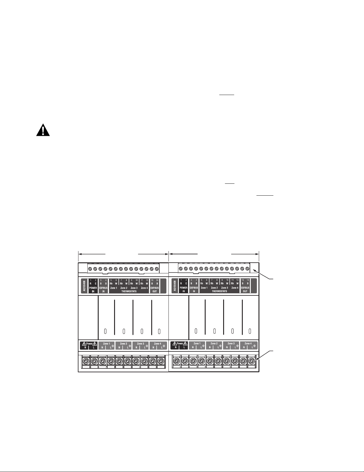
Familiarize Yourself With the AQ255 / AQ257 Expansion Zoning Panel
Refer to Fig. 1 on page 3. In general, the top terminals of all
AQ255 / AQ257 Expansion Zoning Panels carry low voltage
(24Vac) power and the bottom terminals carry either line
voltage (120 Vac) power for the AQ25542B and AQ25582B
models, or low voltage (24 Vac) power for the AQ25742B and
AQ25744B models. The two exceptions to this are:
1. AQ25744B Expansion Zoning Panel for use with zone
valves with
2. AQ25742B Expansion Zoning Panel when used with low
voltage zone valves without end switches.
For these the two exceptions, the bottom terminals of the
AQ10X38 Transformer carry line voltage (120 Vac), but the
bottom terminals of the Zoning Module will carry low voltage
(24 Vac) power.
end switches.
ZONING MODULE
Zone 1
Zone 2
Zone 3
Zone 4
ZONING MODULE
Zone 1
Zone 2
Zone 3
Zone 4
Fig. 1. AQ255 Expansion Zoning Panel Layout (AQ25582B shown).
LOW VOLTAGE
(24 V)
LINE VOLTAGE
(120 V)
M27831A
3 69-1981—06
AQ255 AND AQ257 SERIES EXPANSION ZONING PANELS
TRANSFORMER
LOW
VOLTAGE
(24 V)
LINE
VOLTAGE
(120 V)
Fig. 2. AQ257 Expansion Zoning Panel Layout (AQ25744B shown).
2 MOUNTING
This section describes how to mount the Expansion Zoning
Panels and thermostats.
Mount Expansion Zoning Panel(s)
1. Remove wire channel plugs from the Control Panel and
any Expansion Panels (see Fig. 3).
2. Mount Expansion Zoning Panel on the right-hand end of
the Main Control Panel.
ZONING MODULE
LOW VOLTAGE
(24 V)
Zone 1
Zone 2
Zone 3
Zone 4
LOW VOLTAGE
(24 V)
M27832A
3. Reverse wire channel plugs and re-insert them into their
slot to from a wiring channel between the Main Control
Panel and the Expansion Zoning Panel (see Fig. 3) and
to connect the two panels together.
4. Install two top screws of the Expansion Zoning Panel,
ensuring it is level with the adjoining Main Control Panel,
and install two lower screws.
5. Repeat steps 1–4 for any additional Expansion Zoning
Panels.
Fig. 3. Orientation of wire channel plugs for creating pass-through wire channel and
for joining Main Control Panel to Expansion Zoning Panels.
69-1981—06 4
M13757

AQ255 AND AQ257 SERIES EXPANSION ZONING PANELS
Mount and Wire Thermostats in the Zones
Install the thermostats on the walls in the zones that are to be
controlled by the AQ2000 Control Panels and Expansion
Zoning Panels.
When using AQ1000 thermostats, refer to the included
installation instructions included with that model.
If not done already, run low voltage thermostat wire (24 gauge
or heavier) from the thermostats back to the Expansion Zoning
Panel for use in section 3, “Wiring Procedure” .
NOTE: If not otherwise specified, low voltage wiring
should be run with 18 gauge thermostat wire and
line voltage wiring should be run with 14 gauge
wire. AQUATROL line voltage screw terminals are
approved for use with 22 to 12 gauge copper
conductors.
Several wiring diagrams are included in this
document. For additional information, refer to
http://customer.honeywell.com or your local
distributor.
3 WIRING PROCEDURE
The AQ255 / AQ257 Expansion Zoning Panels are pre-wired at
the factory, making for faster installation.
• For the AQ25742B and AQ25744B models, the low voltage
output terminals located at the top of the transformer are
wired to the R and C input terminals at the top of the Zoning
Module. In addition, for the AQ25742B model, the low
voltage output terminals located at the top of the
transformer are wired to the R and C input terminals at the
bottom of the Zoning Module.
• For the AQ25582B model, which contains two AQ15540B
Zoning Modules, the B-B “Exp.Bus OUT” terminals of the
Zoning Module on the left side are wired to the B-B
“Exp.Bus IN” terminals of the Zoning Module on the right
side.
NOTE: For examples of wiring Expansion Zoning Panels
to AQ2000 Series Control Panels and wiring
additional low voltage VA capacity, refer to the
“Wiring Diagrams” section in the “Appendix”
beginning on page 11.
sitive, so it does not matter which of the BB “Exp.Bus
OUT” terminals is connected to which of the B-B
“Exp.Bus IN” terminals.
4. Wire the zoning equipment to the output terminals (bottom edge) of the Expansion Zoning Panel – line voltage
circulators or valves for the AQ25542B and AQ25582B
and low voltage zone valves for the AQ25742B and
AQ25744B.
5. Bring power to the Expansion Zoning Panel as follows:
a. AQ25542B: run 14 AWG jumper wires from the N
and L terminals on the bottom of the AQ2000 Series
Control Panel’s AQ10X38 transformer to the N and L
terminals on the bottom of the AQ15540B module.
b. AQ25582B: run 14 AWG jumper wires from the N
and L terminals on the bottom of the AQ2000 Series
Control Panel’s AQ10X38 transformer to the N and L
terminals on the bottom of EACH AQ15540B Zoning
Module.
c. AQ25742B: run 14 AWG jumper wires from the N
and L terminals on the bottom of the AQ2000 Series
Control Panel’s AQ10X38 transformer to the N and L
terminals on the bottom of the AQ25742B’s
transformer module (AQ10X38).
d. AQ25744B: run 14 AWG jumper wires from the N
and L terminals on the bottom of the AQ2000 Series
Control Panel’s AQ10X38 transformer to the N and L
terminals on the bottom of the AQ25744B’s
transformer module (AQ10X38).
The AQ255 / AQ257 Expansion Zoning Panels can control up
to 4 space heating zones (or 8, for the AQ25582B Expansion
Zoning Panel). The heart of each Expansion Zoning Panel is its
Zoning Module. The corresponding Panels and Modules are
shown in Table 1 on page 2.
For the -42B and -82B Panels, line voltage pumps are used for
the zoning equipment so low voltage (24 Vac) power is not
required. That’s why there isn't a transformer included with
these Panels. A small amount of low voltage power is required
to power the electronic components inside the Zoning
Modules, and this is supplied by jumper wires connecting the R
and C terminals of the AQ2000 Series Control Panel’s
AQ10X38 transformer with the R and C terminals on the
AQ15540B Zoning Module.
For the -42B and -44B Valve Panels, an AQ10X38 transformer
is included to provide sufficient low voltage power to drive the
zone valves.
Wiring the AQ255 / AQ257 Expansion Zoning Panel to an AQ2000 Series Control Panel
To wire the Expansion Zoning Panel to an AQ2000 Series
Control Panel or another AQ255 / AQ257 Expansion Zoning
Panel:
1. Ensure the power to the AQ2000 Series Main Control
Panel is disconnected before proceeding.
2. For each zone to be added to the existing AQ2000 system, connect one zone thermostat to its corresponding
TH input terminals on the top of the Expansion Zoning
Panel being installed.
3. The B-B “Exp.Bus IN” terminals of the Expansion Zoning
Panel being installed connect to the B-B “Exp.Bus OUT”
terminals on the Control Module or previously installed
Zoning Module on the furthest right side of the AQ2000
Series installation. These connections are polarity insen-
4 CONFIGURE THE EXPANSION
ZONING PANEL(S) DIP
SWITCHES
Setting up the AQ255 / AQ257 Expansion Zoning Panels is
quick, simple and straightforward. All that's needed is to check
and if necessary adjust, the DIP switch settings.
For all Expansion Zoning Panels, DIP switches are located
behind the blank cover in the left most section of the Zoning
Module (beside the section labeled Zone 1). Refer to Fig. 4.
The DIP switches come pre-set from the factory with default
settings that are the most commonly-used by hydronics
contractors across North America. That means that most of the
settings only need to be checked by the installing contractor to
make sure they’re suitable for the job, rather than having to
adjust the DIP switch settings from scratch, which is a great
time savings.
5 69-1981—06
 Loading...