

Page 1
AQUATROL Zone Synchronizing Universal
Injection/Mixing Boiler Reset Controls
AQ252
USER OPERATION AND MAINTENANCE
WARNING
Risk of electrical shock.
Can cause severe injury, property damage or
death.
Only trained, experienced, licensed service
technicians should service this Control Panel. The
front cover of the AQ251 Control Panel should not
be removed, as this will expose the user to
potentially dangerous line voltage (120V)
electricity.
Congratulations!
The AQUATROL AQ252 installed on your heating system is
the most powerful, yet user-friendly hydronic heating control
system available on the market for residential and light
commercial installations.
APPLICATION
The AQ252 series of AQUATROL® Universal Injection/Mixing
Boiler Reset Controls provides simplified, energy-efficient
outdoor temperature compensated control of a hightemperature boiler loop and a lower temperature mixed loop in
residential hydronic heating systems. The AQ252 easily
converts a single-zone heating system into a room-by-room
comfort control system, or upgrades a basic, relay-logic
zoning system to intelligent Zone of Greatest Demand control,
with outdoor reset for increased energy efficiency and with
reduced boiler cycling. The boiler controls of the AQ252 can
ensure ample supply of hot water for both space heating and
priority generation of domestic hot water for bathing, dishes
and laundry.
When AQ1000 communicating thermostats are used with the
AQ252 Zoning Modules, they can use the same wiring as
existing thermostats. Night setback operation can be
programmed from the AQ252 panel.
This AQUATROL AQ252 control panel was installed by a trained hydronic heating contractor.
To service this product, or for any questions relating to its installation, please contact:
Installing contractor: ___________________________________________________________________
Address: _____________________________________________________________________________
This document contains all the information you need to
program the comfort settings of the AQ252 and to customize
its operation for your home or business. For detailed
information on the operation of this control, please consult the
trained hydronic heating professional that installed the AQ252
control.
Application ........................................................................ 1
Familiarization with Control .............................................. 2
User Interface .................................................................. 2
LCD Display Panel Layout ................................................ 3
Programming Instructions ................................................. 4
Troubleshooting ................................................................ 6
System Status and Error Codes ....................................... 6
User Menu Structure ......................................................... 8
CONTENTS
Phone: (________) __________________________________________________________
69-1990-02
Page 2
AQUATROL ZONE SYNCHRONIZING UNIVERSAL INJECTION/MIXING BOILER RESET CONTROLS
A
A
Table 1. AQ252 Models
Model Function DHW Zones Zone Control
AQ25242B Universal Injection/Mixing
Boiler Reset Control Panel
Selectable DHW priority, with
optional priority override
2 – 16,
in sets of 4
Line voltage circulators or 2-wire zone
valves
with integrated zoning
AQ25244B Universal Injection/Mixing
Boiler Reset Control Panel
Selectable DHW priority, with
optional priority override
2 – 16,
in sets of 4
24 Vac zone valves with end switches
with integrated zoning
AQ252 Approvals and Standards:
Canadian Standards Association: Certified, File No. LR76030
Replacement Parts and Accessories:
AQ1000TN2: non-programmable zone thermostat
AQ15200B: Replacement universal injection/mixing reset
boiler control module
AQ15740B: 4-zone valve expansion module
AQ15540B: 4-zone pump expansion module
AQ10X38: 24 Vac 38 VA transformer
AQ12C10: Replacement sensor, outdoor
AQ12C11: Replacement sensor, supply and return on boiler
loop and supply sensor on secondary loop
AQ12C20: Floor / slab sensor
FAMILIARIZATION WITH CONTROL
User Interface
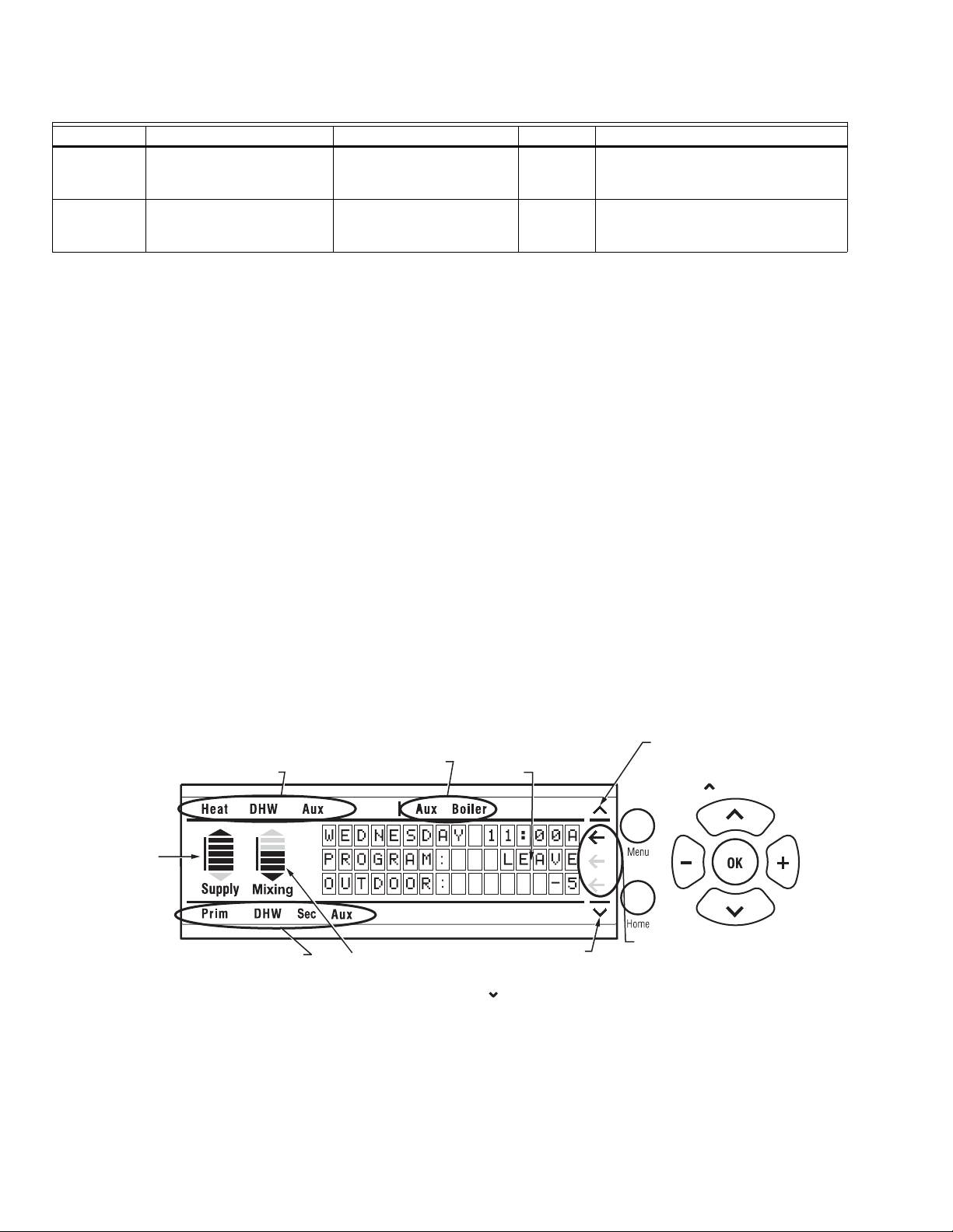
The AQ252 User Interface consists of an LCD screen (16
characters by 3 rows) and a 7-button keypad for navigating
the menus, as illustrated in Fig. 1.
Keypad
The 7- button keypad provides the following functions.
Menu Press this button to access the User Menu. When
pressed while in a sub-menu, the sub-menu’s
values are saved before going up one level in the
current menu.
Home Press this button to leave the User or Installer
Menu and return to the Home Page display screen.
OK Press this button to enter a sub-menu of the active
and v Press these buttons to scroll up/down in the menu
^
– and + Press these buttons to decrease/increase the value
menu item. A menu item is active when the
indicator arrow (←) is positioned beside the item.
items. Pressing one of these buttons automatically
exits the edit mode, and the selection moves to the
previous or next menu item.
of a selected menu item, or to scroll through a list of
pre-defined options.
- If the menu item being modified is a number, the
displayed value will decrease/increase by pressing
these buttons. When holding the – or + button for
more than a second, the values automatically
decrease/increase at a faster pace, similar to
setting the time on a digital clock radio
.
- If the menu item is an option, pressing these
buttons scrolls through the list of available options
one at a time.
STATUS OF SYSTEM DEMANDS
- CALL FOR HEAT
- CALL FOR DHW
- SIGNAL ON AUXILIARY INPUT
GRAPHIC SHOWING
THE PERCENTAGE
OF THE BOILER’S
HEATING CAPACITY
T WHICH IT’S
OPERATING; ARROWS
BOVE AND BELOW
THE BAR SHOW THE
TREND OF THE
BOILER’S
TEMPERATURE
(UP OR DOWN)
STATUS OF LINE VOLTAGE OUTPUTS
- PRIMARY (BOILER) HEAT
- DHW PUMP
- SECONDARY PUMP
- AUXILIARY “PUMP” OUTPUT
69-1990—02 2
STATUS OF SYSTEM OUTPUTS
- AUXILIARY OUTPUT ACTIVE
- BOILER T-T OUTPUT ACTIVE
GRAPHIC SHOWING THE DEGREE OF
MIXING IN THE SECONDARY LOOP:
# OF BARS INCREASES AS A) THE
INJECTION PUMP SPEED INCREASES,
B) THE VOLTAGE OF THE MODULATING
VALVE SIGNAL INCREASES OR C) THE
ACTUAL MIX TEMPERATURE APPROACHES
THE MAXIMUM MIX TEMPERATURE
Fig. 1. LCD display and keypad layout.
DISPLAY AREA SHOWING
SYSTEM STATUS AND MENU
OPTIONS AND SELECTIONS
MADE
DOWN ARROW, IF DISPLAYED,
INDICATES THAT OTHER MENU ITEMS
EXIST BELOW AND CAN BE VIEWED
BY SCROLLING DOWN WITH
THE BUTTON.
UP ARROW, IF DISPLAYED,
INDICATES THAT OTHER MENU
ITEMS EXIST ABOVE AND CAN
BE VIEWED BY SCROLLING
UP WITH THE BUTTON.
?? ARROW INDICATES
?
THE CURRENTLY SELECTED
“ACTIVE” MENU ITEM.
M27698
Page 3

AQUATROL ZONE SYNCHRONIZING UNIVERSAL INJECTION/MIXING BOILER RESET CONTROLS
LCD Display Panel Layout
The LCD on the AQ252 Control Panel is used to:
— Monitor system status and performance.
— Select and/or modify control settings for the hydronic
system.
— Diagnose and troubleshoot system problems.
The layout of the display is logical and simple to navigate. The
information displays so that you can see at a glance the
system’s operating temperatures, as well as the status of the
system equipment, such as a call for heat, DHW pump ON,
Boiler T-T terminals energized, etc. Fig. 1 on page 2 illustrates
the layout and features of the LCD display panel and keypad.
LCD Display Navigation
This section describes how the keypad is used to navigate the
LCD display and menus.
• The LCD displays up to three lines of text at a time. For
menus with more than three lines, use the up and down
buttons (
• As the menu is scrolled up or down, the indicator arrow (←)
shows which menu item is active.
• If the active menu item is part of a list of predefined options
(e.g., Day of the Week) press the – or + button to scroll
through the available options until the preferred option is
displayed. The option is automatically saved when the
indicator arrow is scrolled away from the value being
edited.
• If the active menu item requires you to define a value (e.g.,
a setpoint), use the – or + button to decrease or increase
the value until the desired value is displayed. The selection
will be saved when the indicator arrow is scrolled up or
down.
NOTES:
1. When setting times for the setback schedule, you
2. The OK button, when pressed, defaults the time
or v) to scroll through the menu options.
^
must
use the – or + button to change the time.
setting to “--:--” (midnight).
• If the active menu item leads to a further sub-menu,
pressing the OK button displays the sub-menu options on
the LCD. Scroll through this sub-menu to position the
indicator arrow (←) beside the desired menu item to input
or modify. Choose one of the options provided or input the
desired value for the menu item. When satisfied, scroll to
another item and your selection will be saved.
• To define or modify another item within the same menu,
scroll the up and down buttons (
arrow (←) is beside the desired option. Use the – or +
or v) until the indicator
^
buttons to set the value for that item.
• To move back (up) one level within a menu, press the
Menu button.
• To return to the Home Page display, press the Home
button.
NOTE: The AQ252 automatically returns to the Home Page
display after 60 minutes of inactivity on the keypad.
HOME PAGE DISPLAY
The Home Page is the default view displayed on the AQ252
Control Panel's LCD screen.
There are two Home Page views - Simple and Detail.
• Simple view shows 3 lines of text and is a brief description
of the system operation.
• Detail view includes the same 3 lines plus 10 lines of
additional information. Detail view is the factory default.
The choice of the Simple or Detail Home Page view is made
from the USER MENU > PREFERENCES/TIME menu option.
The Home Page display information for the Simple and Detail
views is illustrated in Fig. 2.
HOME PAGE (SIMPLE)
HOME PAGE (DETAIL)
LCD DISPLAY
WEDNESDAY 9:30A
PROGRAM: LEAVE
OUTDOOR: -5
WEDNESDAY 9:30A
PROGRAM: LEAVE RETRN SLEEP WAKE OCC UNOCC
OUTDOOR: -5
TARGET: 180 WWSD BOILER: 180
RETURN: 160
SECONDARY: 100
SEC TARGET: 100 WWSD DHW: 100
ZONE COUNT: 31
-
-
Fig. 2. Home Page displays (Simple and Detail).
3 69-1990—02
KEYPAD
Menu
Home
M27699
Page 4

AQUATROL ZONE SYNCHRONIZING UNIVERSAL INJECTION/MIXING BOILER RESET CONTROLS
Programming Instructions
Program the AQ252 by using the keypad and LCD display to
select parameters from the User Menu. Refer to Fig. 1 on
page 2 for an illustration of the LCD screen and keypad.
NOTE: The figures in “User Menu Structure” on page 8
provide a graphical layout of the AQ252’s User and
Installer menus.
When a new AQ2000 component is connected on the
AQUATROL network, it will be seamlessly integrated in the
system after a few seconds. If one or more components are
disconnected or stop providing data to the network, a
message will appear on the System Status display until the
fault is corrected.
User Menu Overview
The User Menu is intended for use by the building owner to
choose the LCD display preferences, Zone Settings (including
setpoint temperatures and setback times for each zone), and
temperatures for the WAKE, LEAVE, RETRN (return), and
SLEEP programs.
The Home Page and User Menu allow the building owner to:
• View the status of the system.
• Set up preferences for how the system information is
displayed.
• Set target temperatures for each zone (requires AQ1000
thermostats).
• Program times of the day when the system will set back the
temperatures for all zones (requires AQ1000 thermostats).
NOTE: If there are any problems with the system’s opera-
tion, the AQ252 displays error codes on the System
Status display of the LCD panel. For details on these,
refer to “Troubleshooting” on page 6.
— The time display in 12 hour (e.g., 7:00 PM) or 24 hour
format (e.g., 19:00).
— Date and time of day – allows building owner to reset
day and time of day in the event of a power outage of
more than 4 hours (refer to Troubleshooting section).
— The Home Page display view, Simple or Detail. The
factory default is Detail.
— The LCD Backlight – illuminated permanently (ON) or
set to automatically turn off backlight after 1 hour
(AUTO).
POWER FAILURE
If a power disruption lasts for more than 4 hours, the message
PLS SET DAY/TIME displays and optionally, the AQ252's
backlight flashes repeatedly. This displayed message
continues until the DATE and TIME OF DAY are updated. See
“Power Disruption Greater Than 4 Hours” on page 6.
ZONE SETTINGS (REQUIRES AQ1000 THERMOSTATS)
Settings in this sub-menu define:
— The temperature setpoints (target temperatures) for
each zone in the heating system.
— The temperature setback for each zone in the heating
system. This is the desired temperature drop when the
heating system enters the setback program SLEEP or
LEAVE.
— The maximum and minimum setpoints that can be
entered by a user at a thermostat screen for each
zone.
— Whether each zone can be set independently by the
AQ252 (i.e., some zones can be locked while others
are unlocked) depending on whether or not the keyboard on a thermostat is locked. When locked, no
changes can be made to a zone’s setpoint temperature through the thermostat. Changes can still be
made through the Zone Settings menu on the AQ252
control panel.
TO ACCESS THE USER MENU:
Press the Menu button on the keypad at any time to access
the User Menu.
User Menu Settings
The User menu has five sub-menus.
• “System Status”
• “Preferences/Time”
• “Zone Settings (requires AQ1000 thermostats)”
• “Program Settings”
• “Statistics” on page 5
To make changes to the parameter settings in the User Menu,
refer to “LCD Display Navigation” on page 3.
SYSTEM STATUS
This is a detailed list of activities going on in the heating
system (e.g., call for heat, DHW disabled), and provide the
building owner with a quick snapshot of the heating system’s
operation, primarily for purposes of troubleshooting and
system diagnostics.
PREFERENCES/TIME
The preferences that the building owner can change in this
sub-menu are:
— The temperature scale for the display (Fahrenheit or
Celsius) for both the AQ252 control’s LCD and the
zone thermostats.
PROGRAM SETTINGS
Using the Program Settings sub-menu, the building owner can
define the time of day when the entire heating system will
change programs (e.g., from SLEEP to WAKE).
The AQ252 has provision for four different schedule periods
per day. They are defined as WAKE, LEAVE, RETRN (return),
and SLEEP:
WAKE: Period when you awaken and want your
home at a comfortable temperature.
LEAVE: Period when you are away from home and
want an energy-saving temperature.
RETRN: Period when you return home and want
your home back to a comfortable
temperature.
SLEEP: Period when you are asleep and want an
energy-saving temperature.
There are three modes of operation – Automatic, Occupied
and Unoccupied:
AUTO: In AUTO mode, the AQ252 follows the
WAKE, LEAVE, RETRN, and SLEEP
programs.
OCC: In OCC mode, the AQ252 holds the
temperature of OCCUPIED programs
(WAKE and RETURN). This might be used
if the occupancy pattern of the building
69-1990—02 4
Page 5

AQUATROL ZONE SYNCHRONIZING UNIVERSAL INJECTION/MIXING BOILER RESET CONTROLS
changes temporarily, requiring the
temperature to be at a comfort level 24
hours/day.
UNOCC: In UNOCC mode, the AQ252 holds the
temperature of UNOCCUPIED programs
(LEAVE and SLEEP). This might be used if
the building will be unoccupied for an
extended period of time, such as a vacation
period.
There are two ways to set the schedule program times for
WAKE, LEAVE, RETRN, and SLEEP:
— One day at a time
— All days at the same time
1. One day at a time programming:
• Select EDIT DAILY from the Program Settings submenu.
• A list of four program times per day displays,
showing the factory pre-set times for all programs:
MON WAKE 6:00A
MON LEAVE 8:00A
MON RETRN 4:30P
MON SLEEP 10:00P
TUE WAKE 6:00A
TUE LEAVE 8:00A
TUE RETRN 4:30P
TUE SLEEP 10:00P
…
SAT WAKE 6:00A
SAT LEAVE --:-SAT RETRN --:-SAT SLEEP 10:00P
SUN WAKE 6:00A
SUN LEAVE --:-SUN RETRN --:-SUN SLEEP 10:00P
• Any of the times can be changed by scrolling to that
line and pressing the + or – button until the desired
program time is displayed.
2. Programming all days at the same time:
• Select EDIT ALL DAYS from the Program Settings
sub-menu.
• A sub-menu displays where you can change the
WAKE program time for all days, the LEAVE
program time for all days, etc.
• When all four programs have been set, select the
COPY TO ALL DAYS option. This displays the
prompt: COPY TO ALL DAYS - ARE YOU SURE?.
Select Yes by positioning the indicator arrow at YES
and press the OK button.
• Next, the same list of days as EDIT DAILY
(described in step 1) displays, except that all days
now show the times for the WAKE, LEAVE, RETRN,
and SLEEP programs that you set in the EDIT ALL
DAYS menu.
• If you do not want all days of the week to have the
same program schedule (e.g., weekdays different
than weekends), you can now scroll down and
change the program times for certain days by
positioning the indicator arrow beside the program
time to change and using the + or – button to
increase or decrease the scheduled program time.
When the program times have been set for all days, press the
Home button to leave the programming menus and return to
the Home Page display. All settings take effect immediately.
NOTES:
1. Schedule times are in 15-minute intervals.
2. To have the AQ252 ignore a program change
(and therefore keep the previous program's setpoint temperature), position the cursor beside the
period to be ignored and press the OK button.
The AQ252 will display “--:--” beside that program
and, when operating, will continue with the previous program's setpoint until the next program
change.
STATISTICS
This sub-menu provides information about system activity and
mix valve cycle counts. See Fig. 3 on page 8 for an illustration
of the statistical data that can be displayed.
5 69-1990—02
Page 6

AQUATROL ZONE SYNCHRONIZING UNIVERSAL INJECTION/MIXING BOILER RESET CONTROLS
TROUBLESHOOTING
Power Disruption
The AQ252’s system and thermostat (zone settings)
parameters are stored in non-volatile memory and are
updated as they change.
When a power disruption or loss of power occurs, the system
configuration is retained in memory.
When power is restored, the AQ252 Control Panel enters
auto-detection mode, reads its previously-stored settings, and
initializes all AQUATROL network components according to
their saved parameters.
POWER DISRUPTION GREATER THAN 4 HOURS
If a power disruption lasts for more than 4 hours, the AQ252
will have discharged its internal super capacitor, and the
DATE and TIME OF DAY settings will need to be reset.
Table 2. LCD Status Notices and Error Messages.
LCD Display Parameter Meaning
A/C MIN. OFF TIME n/a The A/C compressor is disabled, because the minimum OFF time has not yet elapsed.
A/C MIN. ON TIME n/a The A/C compressor is active and the minimum ON time has not yet elapsed.
AUX IN EM. SHUT n/a Auxiliary Input's Emergency Shut Down is active.
BOILER: EM SHUT Boiler is disabled, because the AQ252 is in Emergency Shut Down mode.
FRZ PROT Boiler freeze protection activated:
• Communication between Control Module and Zoning Module has been lost for more
than 1 minute
or
• Boiler supply temperature is less than 50°F (10°C)
HEAT DHW Boiler is active to serve DHW.
HEATING Boiler is active to serve zones.
IDLE Boiler is not active.
INIT Boiler contacts (terminals 22 and 23) on the AQ1520, which are connected to the boiler's
T-T terminals, have been shorted and the boiler is beginning its firing sequence.
INST PURG Boiler is active while the AQ252 is conducting the PURGE operation in the Installer
Setup.
INSTALL Boiler is in ready mode during Installer Setup.
PMP EXER Boiler is disabled while the AQ252 is exercising all pumps and valves connected to the
POST PURG Boiler is active with Post Purge operation and is sending the purged water to the Boiler
PURGE DHW Boiler is active with Post Purge operation and is sending the purged water to the DHW
CALL FOR COOL n/a At least one zone with a programmable thermostat requires cooling.
CALL FOR DHW n/a The DHW requires heat.
CALL FOR HEAT n/a At least one zone requires heat.
CWSD ACTIVE n/a Zone calls for cooling are not served because CWSD (Cold Weather Shutdown) is in
DHW DISABLE n/a DHW call is not served because it is disabled.
INJECTION%: xx% n/a The variable speed injection pump terminals are active and operating at xx% of full
LOST ZONE A-1
…
LOST ZONE D-16
n/a Lost communication with a zone (A-1 to A-16, B-1 to B-16, C-1 to C-16, or D-1 to D-16).
AQUATROL network.
(Primary) loop.
tank.
progress.
speed.
Upon restart, the AQ252 displays its clock settings as: YEAR
= 2008, MONTH = JAN, DATE = 1. The message PLS SET
DAY/TIME displays. This displayed message continues until
the DATE and TIME OF DAY are updated.
NOTE: If the power failure parameter is set to Backlight
(USER MENU > PREFERENCES/TIME), the LCD
backlight flashes repeatedly, along with the message.
The AQ252 remains permanently in OCCUPIED (or Comfort)
mode until the DAY and TIME OF DAY are updated.
System Status and Error Codes
System status alerts and error messages display on the
System Status Page. These messages are shown in Table 2.
69-1990—02 6
Page 7

AQUATROL ZONE SYNCHRONIZING UNIVERSAL INJECTION/MIXING BOILER RESET CONTROLS
Table 2. LCD Status Notices and Error Messages. (Continued)
LCD Display Parameter Meaning
MIN. RETURN PROT n/a The temperature measured by the return sensor is at or below the minimum return water
temperature.
NO DHW PROBE n/a No DHW sensor connected or it is defective.
NO LINE VOLTAGE n/a No line voltage has been detected on the N and L terminals on the line voltage input to
the control module.
NO OUTDOOR PROBE n/a No outdoor sensor connected or it is defective.
NO RETURN PROBE n/a No return sensor connected or it is defective.
NO SECOND. PROBE n/a No secondary (mixed) loop sensor connected or it is defective.
NO SUPPLY PROBE n/a No supply sensor connected or it is defective.
SHORT CYCLE PROT n/a There is a call for heat, but less than two minutes have elapsed since the last firing of the
boiler (prevents short cycling).
VALVE INIT n/a Motorized mixing valve controlling the secondary loop is being initialized and
repositioned (opening or closing) to meet the secondary loop target temperature.
WATER READY n/a Boiler Supply Water temperature is at or above the target temperature calculated by the
AQ252.
WWSD ACTIVE n/a Zone calls for heat is not served because WWSD (Warm Weather Shutdown) is in
progress.
When a new AQ2000 component is connected on the
AQUATROL network, its settings are communicated to the
AQ252's Boiler Control Module (AQ15200B) within 10
seconds of being connected. If the component is an AQ1000
thermostat, the setpoints for that zone thermostat can be
modified from the Boiler Control Module as soon as it is
recognized by the Control Module.
When an AQ thermostat is disconnected from the AQUATROL
network, a message displays on the System Status page of
the AQ252 indicating “Lost Zone A-xx”, where “xx” is the
specific identity, or address, of the lost zone. This helps the
servicing contractor quickly identify the lost zone and fix its
wiring, to re-establish communication with the Control Module.
7 69-1990—02
Page 8

AQUATROL ZONE SYNCHRONIZING UNIVERSAL INJECTION/MIXING BOILER RESET CONTROLS
USER MENU STRUCTURE
Press the Menu button on the keypad to display the User Menu. Fig. 3 illustrates all possible User Menu selections.
USER MENU
SYSTEM STATUS
PREFERENCES/TIME
ZONE SETTINGS
PROGRAM SETTINGS
STATISTICS
SYSTEM STATUS
A/C MIN OFF TIME
A/C MIN ON TIME
AUX IN EM.SHUT
BOILER: IDLE
CALL FOR COOL
CALL FOR DHW
CALL FOR HEAT
CWSD ACTIVE
DHW DISABLE
INJECTION%: 0%
LOST ZONE A-1
...
LOST ZONE D-16
MIN RETURN PROT
NO DHW PROBE
NO LINE VOLTAGE
NO OUTDOOR PROBE
NO RETURN PROBE
NO SECOND. PROBE
NO SUPPLY PROBE
SHORT CYCLE PROT
VALVE INIT
WATER READY
WWSD ACTIVE
1
THE SYMBOLS INDICATE ADDITIONAL SELECTIONS ARE POSSIBLE.
THE FACTORY DEFAULT VALUES ARE SHOWN.
TEMPERATURE VALUES ARE SHOWN IN DEGREES FAHRENHEIT,
2
WHICH IS THE FACTORY DEFAULT TEMPERATURE UNIT.
3
EITHER HEAT OR COOL DISPLAYS DEPENDING ON THE SYSTEM’S STATUS.
4
FACTORY DEFAULT TIMES FOR MON THROUGH FRI.
FACTORY DEFAULT TIMES FOR SAT AND SUN.
5
PREFERENCES / TIME
BOILER UNITS: °F
ZONE UNITS: °F
TIME DISP: 12H
D.S.T.: ENABLE
YEAR: 2008
MONTH: JAN
DATE: 1
DAY: MONDAY
TIME: 12:00A
HOMEPAGE: DETAIL
BACKLIGHT: AUTO
POWER FAILURE
NOTICE: BACKLIGHT
1
ZONE SETTINGS (All or Single)
EDIT ALL ZONES
EDIT SINGLE ZONE
ARE YOU SURE?
NO YES
ZONE A-1
ROOM TEMP
FLOOR TEMP
SETPOINT: 70
FLOOR SETPT: 70
HEAT/COOL STATUS
SETBACK: 7
SETPOINT MAX: 100
SETPOINT MIN: 41
FLOOR LIM HI: 100
FLOOR LIM LO: 41
SETPOINT VACANCY
HEAT: 41
SETPOINT VACANCY
COOL: 100
CHANGEOVER: 2
KEYBOARD: UNLOCK
PROGRAM SETTINGS
MODE: AUTO
EDIT ALL DAYS
EDIT DAILY
2
EDIT ALL DAYS
3
ALL WAKE 6:00A
ALL LEAVE 8:00A
ALL RETRN 4:30P
ALL SLEEP 10:00P
COPY TO ALL DAYS
COPY WAKE
COPY LEAVE
COPY RETRN
COPY SLEEP
EDIT DAILY
MON WAKE 6:00A
MON LEAVE 8:00A
MON RETRN 4:30P
MON SLEEP 10:00P
...
SUN WAKE 6:00A
SUN LEAVE --:--
SUN RETRN --:--
SUN SLEEP 10:00P
STATISTICS
LAST DATA RESET: 2000 JAN 01
BOILER FIRE ACTIV: 0H
BOILER PUMP ACTIV: 0H
DHW PUMP ACTIV: 0H
AUX PUMP ACTIV: 0H
SEC PUMP ACTIV: 0H
INJ PUMP ACTIV: 0H
AUX OUT ACTIV: 0H
MIX VLV. OPEN CYCLE: 0
MIX VLV. CLOSE CYCLE: 0
ZONE A-1
ACTIV: 0H
ARE YOU SURE?
NO YES
4
5
M27700
Fig. 3. User Menu Structure.
AQUATROL® is a registered trademark of Honeywell International Inc.
Automation and Control Solutions
Honeywell International Inc. Honeywell Limited-Honeywell Limitée
1985 Douglas Drive North 35 Dynamic Drive
Golden Valley, MN 55422 Toronto, Ontario M1V 4Z9
customer.honeywell.com
® U.S. Registered Trademark
© 2009 Honeywell International Inc.
69-1990—02 M.S. Rev. 09-09
 Loading...