

Honeywell AQ252 Product Information Sheet
69-1986-05
AQ252 Universal Injection/Mixing
Boiler Reset Control Panels
PRODUCT DATA
FEATURES
The AQ252 family have the following features:
• Controls one boiler loop and one mixed temperature
loop.
• Outdoor temperature compensation (reset), or Load
reset based on indoor temperature feedback, or none.
• Zone synchronization through Zone of Greatest
Demand control.
• Domestic hot water (DHW) priority and priority
override protection.
• Customizable control settings and schedules allow for
greater level of control and comfort.
• Use of variable speed injection pump or motorized
mixing valve for mixed temperature loop control.
PRODUCT DESCRIPTION
The AQ252 family of AQUATROL® Universal Injection/Mixing
Boiler Reset Controls provides simplified, energy-efficient
outdoor temperature compensated control of a hightemperature boiler loop and a lower temperature mixed loop in
residential hydronic heating systems. The AQ252 easily
converts a single-zone heating system into a room-by-room
comfort control system, or upgrades a basic, relay-logic
zoning system to intelligent Zone of Greatest Demand control,
with outdoor reset for increased energy efficiency with
reduced boiler cycling. The boiler controls of the AQ252 can
ensure ample supply of hot water for both space heating and
priority generation of domestic hot water for bathing, dishes
and laundry.
• Central set-back schedules available.
• Zoning Control for up to four, single-stage or two, twostage zones as shipped; can be expanded to a total of
16 zones with AQ255 or AQ257 expansion zoning
panels, and up to 64 zones by using up to three AQ254
Add-a-Temperature expansion panels and additional
expansion zoning modules.
IMPORTANT
To ensure correct installation and proper operation of
the control, perform the 7 installation steps in the
order numbered in the “Contents” below.
Contents
Specifications ................................................................... 2
1 Installation Preparation .................................................. 3
2 Mounting ........................................................................ 5
3 Wiring Procedure ........................................................... 7
4 Program and Configure the Control Panel ..................... 15
5 Test and Check Out the Installation ............................... 20
6 Purge Air from all System and Zone Piping .................. 21
7 Document and Keep a record of all System Settings .... 21
Troubleshooting ................................................................ 22
Appendix .......................................................................... 25
User Menu .............................................................. 25
Installer Menu ......................................................... 32

• Use with digital non-communicating thermostats or
AQ1000 2-wire polarity insensitive communicating
thermostats. Note: When using non-communicating
thermostats, the following features are not available:
• Outdoor temperature is not displayed on the
thermostat.
• Time clock on AQ1000TP2 will not synchronize
with the Control Module.
• Central programming, vacancy and setback
schedules of AQ1000 from AQ panel are not
enabled.
• AQ panel will not display individual zone
temperatures.
• Individual zone freeze protection.
• Allows display of outdoor temperature on all AQ1000
thermostats when used with an AQ12C10 outdoor
sensor (included).
• Intuitive programming interface (can be programmed
at your shop and taken to the job site “ready-toinstall”).
• Automated test and purge feature for quick start-up
and simplified troubleshooting.
• Boiler freeze protection and single-zone freeze
protection.
• Pump/valve exercise.
• Boiler short cycling protection, post purge, and shock
prevention from cold water returning to boiler.
• Line or low-voltage output for zoning equipment
(pumps or valves).
• Integral 38 VA transformer with self resetting
electronic fuse.
• 4 hour power supply (super capacitor) retains day and
time settings during power outage and a non-volatile
EPROM memory retains program settings during
power outage.
SPECIFICATIONS
The AQ252 Control Panels and corresponding attached
equipment are listed in Table 1.
Table 1. AQ252 Series Control Panel Models.
Corresponding
Control Panel
AQ25242B AQ15200B AQ15540B
AQ25244B AQ15200B AQ15740B
Application: Controls one boiler and one mixed temperature
loop (using either a variable-speed injection pump or
motorized valve mixing), as well as domestic hot water
(DHW) management and zoning operation in a hydronic
zoning system.
Power and Electrical Ratings:
Power Supply: 120 Vac / 60Hz
Auxiliary Pump Output Rating: Dry contact output,
120/250 Vac 5A, 1/3 HP
Auxiliary Low Voltage Output Rating: 24 Vac, 0.5A,
12VA
Boiler (T-T) Output Rating: 24 Vac, 0.5A, 12VA
Boiler Pump (C1-C2) Output Rating: 120 Vac 5A, 1/3HP
DHW Pump/Valve Output Rating: 120 Vac 5A, 1/3HP
Secondary Pump Output Rating: 120 Vac 5A, 1/3HP
Variable-Speed Injection Pump Output: Tr ia c
modulated; 120 Vac 2.1A, 1/6HP
B–B Communication Bus Terminals: Low voltage,
Class II, 2-wire polarity-insensitive, digital
communicating link to other Control or Zoning modules.
Electrical Connections (Line Voltage): Wire-clamp
screw terminals; maximum 2 x 14 AWG each on line
voltage terminals
Environmental Ratings:
Control and Zoning Panel Temperature Rating: 32°F to
130°F (0°C to 55°C)
Operating Humidity Range (% RH): 5 to 90% RH, non-
condensing
Control Module
Corresponding
Zoning Module
Temperature Ratings:
Boiler Design Temperature: 80°F to 210°F (26°C to
99°C)
ORDERING INFORMATION
When purchasing replacement and modernization products from your TRADELINE® wholesaler or distributor, refer to the
TRADELINE® Catalog or price sheets for complete ordering number. If you have additional questions, need further information,
or would like to comment on our products or services, please write or phone:
1. Your local Honeywell Environmental and Combustion Controls Sales Office (check white pages of your phone directory).
2. Honeywell Customer Care
1885 Douglas Drive North
Minneapolis, Minnesota 55422-4386
3. http://customer.honeywell.com or http://customer.honeywell.ca
International Sales and Service Offices in all principal cities of the world. Manufacturing in Belgium, Canada, China, Czech
Republic, Germany, Hungary, Italy, Mexico, Netherlands, United Kingdom, and United States.
69-1986—05 2

Boiler Differential: 2°F to 41°F (1°C to 23°C), or Auto
Boiler (Supply) Minimum Control Temperature: OFF,
59°F to 180°F (OFF, 15°C to 82°C)
Boiler (Supply) Maximum Control Temperature: OFF,
120°F to 225°F (OFF, 49°C to 107°C)
Outdoor Low Design Control Temperature: -60°F to
32°F (-51°C to 0°C)
Return Minimum Control Temperature: OFF, 80°F to
180°F (OFF, 27°C to 82°C)
Secondary Loop Mixing (Supply) Design Temp
Range: 70°F to 210°F (21°C to 99°C)
Secondary Loop Mixing (Supply) Min. Control Temp
Range: OFF, 35°F to 150°F (OFF, 2°C to 66°C)
Secondary Loop Mixing (Supply) Max. Control Temp
Range: OFF, 80°F to 210°F (OFF, 27°C to 99°C)
Sensor Temperature Rating: -58°F to 230°F (-50°C to
110°C)
Warm Weather Shut Down (WWSD) Temperature: OFF,
35°F to 100°F (OFF, 1°C to 38°C)
Cold Weather Shut Down (CWSD) Temperature: OFF,
32°F to 100°F (OFF, 0°C to 38°C)
Inputs/Outputs:
Auxiliary (Demand) Input: External dry contacts
connection only
DHW Demand Input: External dry contacts connection
only
Heat Demand (Thermostat R-W) Input: External dry
contacts connection only
Modulating Output: )-10 or 2-10 Vdc for variable speed
pump or modulating boiler
Mixing Valve (Com, O, C): 324 Vac, 0.5A, 12VA
R–C Input (on Control and Zoning Modules): 24 Vac
Class II
R–C Output (on transformer): 38 VA, 24 Vac Class II
Interface and Timings:
User Interface (Setting, Programming): LCD Display
and a 7-button keypad
Setback Program: 7 day, up to 2 setback periods/day.
Boiler Heat Post Purge: Off, 10 seconds to 30 minutes
(factory default is 30 seconds)
Pump/Valve exercise: 30 seconds per 2 weeks of space
heating inactivity
Thermostat Compatibility: Digital non-communicating
thermostats and/or AQ1000 Series 2-wire communicating
thermostats
Supply/Return/Secondary (Mixed) Loop Sensor: 10K ohm
NTC thermistor at 77°F (25°C) ± 0.5°F (±0.3°C). Lead
length: 10 ft. (3.0 m); up to 500 ft. (150 m) using 18 AWG or
larger wire, beta=3892.
Outdoor Sensor: 10K ohm NTC thermistor at 77°F (25°C) ±
0.5°F (±0.3°C). Lead length: 15 ft. (4.6 m); up to 500 ft. (150
m) using 18 AWG or larger wire, beta=3892
Dimensions (HxWxD): 8 x 16 1/2 x 3 3/8 in. (20.3 x 42 x
8.5 cm) approximate
Weight: 4.9 lb. (2.3 kg)
Approvals: Canadian Standards Association: Certified, File
No. LR76030
1 INSTALLATION PREPARATION
NOTES: Throughout these instructions, the following
terminology conventions are used:
— AQ155 refers to the AQ15540B Zoning Module.
— AQ157 refers to the AQ15740B Zoning Module.
— AQ1520 refers to the AQ15200B Control Module within
an AQ252 Series Control Panel.
— AQ252 refers to the AQ25242B and AQ25244B Control
Panels. Where there are specific instructions or details
relating to the -42B or -44B Control Panels, the full
model number (i.e., AQ25244B) is used.
— AQ255 refers to all of the AQ25542B, AQ25582B and
AQ25742B Expansion Zoning Panels.
— AQ257 refers to the AQ25744B Expansion Zoning
Panel. Where there are specific instructions or details
relating to the -542B, -582B, -742B, or - 744B
Expansion Zoning Panels, the full model number (i.e.,
AQ25744B) is used.
— Control Module refers to the component within an
AQ252 Series Control Panel that performs the master
control operations. See Table 1 on page 2 for specific
models.
— Control Panel refers to an assembled product,
consisting of a transformer, Control Module and Zoning
Module, all contained within an AQ2000 panel
enclosure.
— Expansion Zoning Panel refers to an assembled
product, consisting of a Zoning Module and (if
applicable) a transformer, contained within an AQ2000
panel enclosure. Expansion Zoning Panels are
available in either 4-zone or 8-zone configurations.
— Zoning Module refers to the component within the
AQ252 Series Control Panel that controls zoning
operations.
When Installing this Product…
1. Read these instructions carefully. Failure to follow
them could damage the product or cause a
hazardous condition.
2. Check the ratings given in the instructions and on
the product to make sure the product is suitable for
the application.
3. Installers must be trained, experienced, and licensed
service technicians.
4. Follow local codes for installation and application.
5. After installation is complete, check out the product
operation as printed in these instructions.
3 69-1986—05

WARNING
Risk of electrical shock.
Can cause severe injury, property damage or death.
Disconnect power supply before installation and before
servicing.
Check That You Have All the Necessary Equipment For a Successful Installation
• AQ2000 Series components:
— AQ252 Control Panel
— AQ Expansion Zoning Panels (if more than four space
heating zones in the system)
— Digital thermostats (one for every space heating zone
being controlled)
• Boiler supply and return temperature sensors and
secondary loop sensor (included with the AQ252 Control
Panel)
• Outdoor temperature sensor (included with AQ252 Control
Panel)
• Low voltage thermostat wire
• Zoning equipment (zone valves or pumps)
Read All Instructions Carefully Before Proceeding
The AQ252 Control Panels are a part of a totally new family of
hydronic controls. And although they - and other AQ2000
system components - are very easy to install and operate, they
are different than other hydronic controls that you have
previously installed. So take a moment to read through this
quick installation guide before
Failure to follow them could damage the product or cause a
hazardous condition.
beginning the installation.
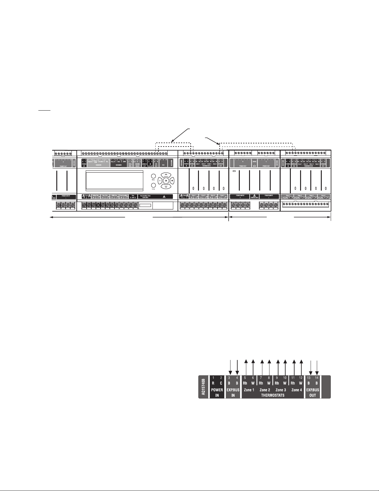
Familiarize Yourself With the AQ252 Control Panel Layout
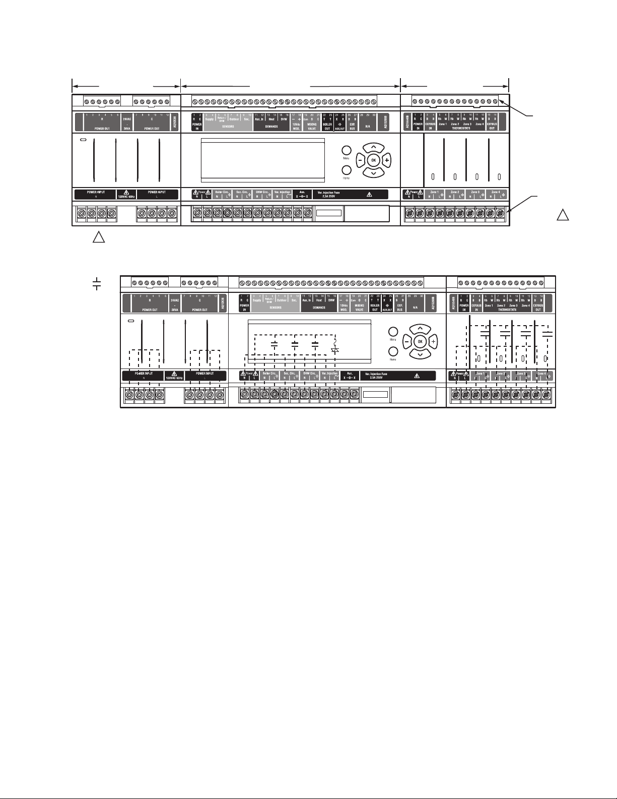
Refer to Fig. 1. All AQ252 Control Panels consist of three
functional components:
1. AQ10X38 transformer (power supply module), which
connects to 120 Vac power and supplies 24 Vac power to
the Control Module and Zoning Modules
2. AQ15200B boiler/DHW Control Module, which controls
the boiler and domestic hot water (DHW) functions,
mixing operation for the secondary loop, as well as
coordinating the overall operation of the hydronic
system.
3. One of two different 4-zone Zoning Modules:
• AQ15740B (part of the AQ25244B Control Panel) for
zoning with 24 Vac zone valves with
• AQ15540B (part of the AQ25242B Control Panel) for
zoning with either line voltage circulators or 24 Vac
zone valves without
AQ252 Control Panels can control a maximum of 16 zones by
connecting additional Expansion Zoning Panels to the AQ252
Control Panel. Each Expansion Zoning Panel is configured with
its own bank of DIP switches, located in the left-most section of
each Zoning Module. To expand the capacity of an AQ252
Control Module beyond 16 zones, an AQ254 Add-ATemperature Expansion Control Panel is required. The
hydronic system can be expanded by 16 zones for each AQ254
connected to the AQ2000 network. A maximum of three (3)
AQ254 Panels may be connected to an existing AQ2000
Control Panel for a maximum of 64 zones connected on the
AQUATROL network.
In general, the top terminals of the AQ2000 Series
components carry low voltage (24 Vac) power and the bottom
terminals carry line voltage (120 Vac) power. This is illustrated
in Fig. 1. The two exceptions to this are:
1. AQ15740B Zoning Module for use with zone valves with
end switches.
2. AQ15540B Zoning Module when used with low voltage
zone valves without
For these the two exceptions, the bottom terminals of the
Transformer and Control Module carry line voltage (120 Vac),
but the bottom terminals of the Zoning Module will carry low
voltage (24 Vac) power.
end switches.
end switches.
end switches.
69-1986—05 4
The powered terminals on the bottom of the AQ2000 Series
Control Modules and Zoning Modules are connected internally,
as shown in Fig. 2 on page 5. The voltage supplied to the N
and L terminals is also available at the adjacent terminal pairs
when the hot ( ) relays are switched.
TRANSFORMER
M27683A
CONTACTS
SYMBOL
Zone 1
Zone 2
Zone 3
Zone 4
CONTROL MODULE
ZONING MODULE
LOW
VOLTAGE
(24 V)
FOR THE AQ25242B TERMINALS CAN BE LINE VOLTAGE (IF USED WITH PUMPS) OR LOW VOLTAGE (IF USED WITH ZONE VALVES)
1
2 MOUNTING
Zone 1
Zone 2
Fig. 1. AQ252 Control Panel layout (AQ25242B shown).
Fig. 2. Internal wiring for AQ2000 Series components line voltage relays.
Zone 3
Zone 4
LINE
VOLTAGE
(120 V)
M27682A
1
This section describes how to mount the Control Panel,
Expansion Zoning Panels, and the Thermostats.
Mount AQ252 Control Panel
Mount the control panel on the wall:
1. Use the template supplied with the AQ252 Series
Control Panel to mark mounting holes for panels.
2. Install two top screws, mount the panel, and install the
two lower screws.
Mount Expansion Zoning Panel(s)
If there are Expansion Zoning Panels to install, mount them to
the wall now:
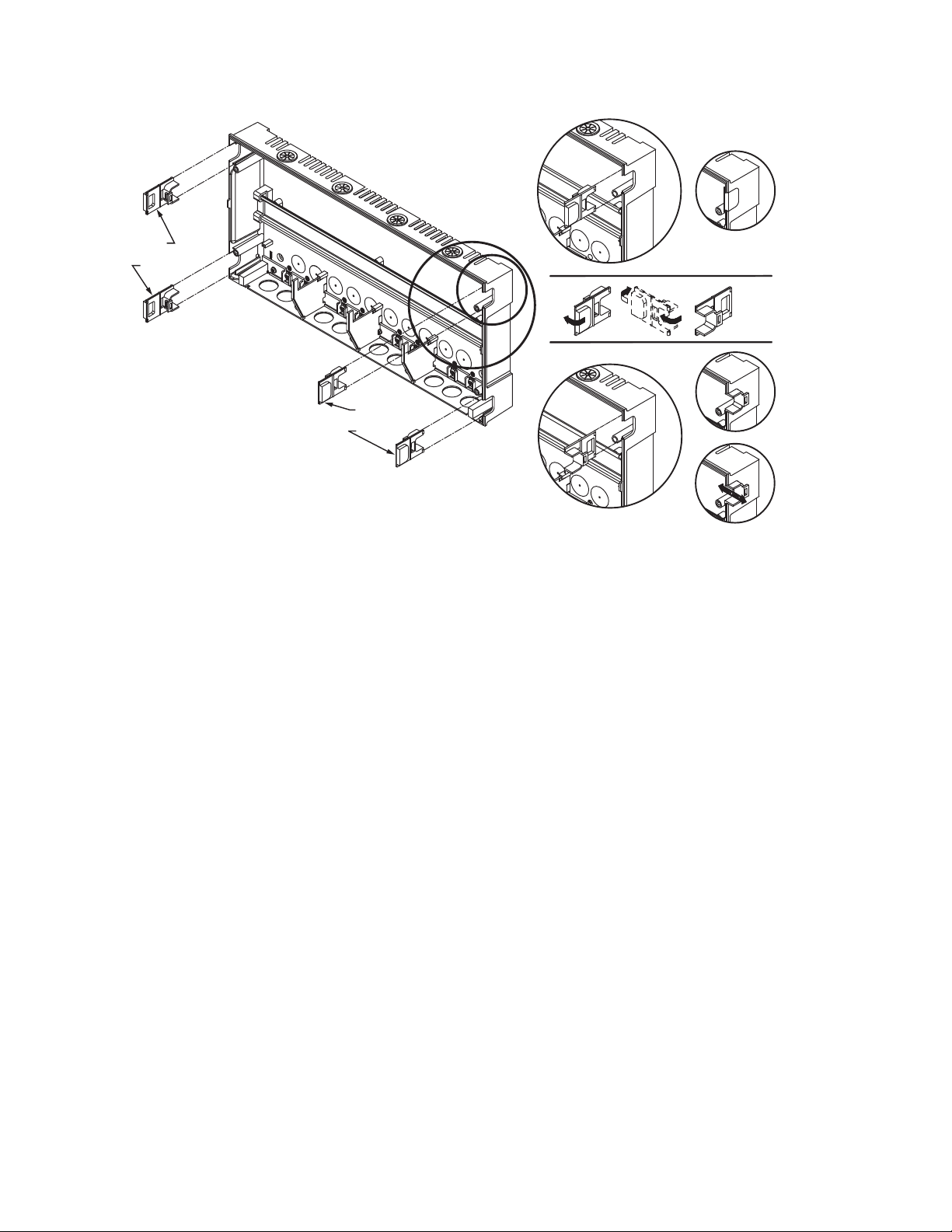
1. Remove wire channel plugs from the AQ252 Control
Panel and any Expansion Zoning Panels (see Fig. 3).
2. Mount Expansion Zoning Panel on the right-hand end of
the AQ252 Control Panel. Install two top screws of the
Expansion Zoning Panel, ensuring it is level with the
adjoining Control Panel, and install two lower screws.
3. Reverse wire channel plugs and re-insert them into their
slot, to form a wiring channel between the Control Panel
and the Expansion Zoning Panel (see Fig. 3) and to
connect the two panels together.
4. Repeat steps 1–3 for any additional Expansion Zoning
Panels.
5 69-1986—05
M23733A
WIRE
CHANNEL
PLUGS
WIRE
CHANNEL
PLUGS
Fig. 3. Orientation of wire channel plugs for creating pass-through wire channel and
for joining Control Panel to Expansion Zoning Panels.
69-1986—05 6
Mount and Wire Thermostats in the Zones
Install the thermostats on the walls in the zones that are to be
controlled by the AQ252 Control Panel.
When using AQ1000 thermostats refer to the installation
instructions (form #69-2005) included with the AQ1000
thermostats.
If not done already, run low voltage thermostat wire (24 gauge
or heavier) from the thermostats back to the Zoning Modules
connected to the AQ252 Control Panel.
3 WIRING PROCEDURE
NOTES: If not otherwise specified, low voltage wiring should
be run with 18 gauge thermostat wire and line voltage
wiring should be run with 14 gauge wire.
AQUATROL
®
line voltage screw terminals are only
approved for use with 22 to 12 gauge copper
conductors.
Several wiring diagrams are included in this
document. For additional information, refer to
http:// customer.honeywell.com or your local
distributor.
The AQ252 Control Panel is pre-wired at the factory, making for
faster installation.
For all models, the low voltage output terminals located at the
top of the transformer secondary are wired to the R and C input
terminals of the Control Module, as well as the R and C inputs
of the Zoning Module. The B-B Exp. Bus terminals (26 and 27)
of the Control Module are wired to the B-B Exp. Bus IN
terminals of the Zoning Module.
TO EXPANSION ZONING MODULES
(IF INSTALLED)
STEP 1 STEP 2 STEP 3
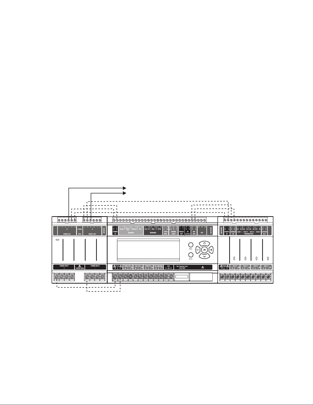
Beginning with the top left of Fig. 4 and moving clockwise
around the panel, wire components to the AQ252 Control
Panel and Expansion Zoning Panels (if installed) in the
following six steps:
• “Step 1 – Transformer Wiring”
• “Step 2 – Control Panel Wiring”
• “Step 3 – Thermostats Wiring” on page 9
• “Step 4 – Zoning Equipment Wiring” on page 10
• “Step 5 – Line Voltage System Outputs” on page 13
• “Step 6 – Connection To Line Voltage Power” on page 14
Zone 1
Zone 2
Zone 3
Zone 4
Fig. 4. Wiring sequence.
Step 1 – Transformer Wiring
Factory pre-wiring of the Control Panels is shown as dotted
lines in Fig. 4.
In addition to the pre-wiring, run low voltage jumper wires from
available R and C terminals on the secondary of the
transformer to the R and C terminals of any Expansion Zoning
Panel.
STEP 4STEP 5STEP 6
M27684A
Step 2 – Control Panel Wiring
Wire the Temperature Sensors, System Demands, Low
Voltage Outputs, and Communication Bus (Refer to Fig. 5 on
page 8 for wiring terminals on the top of the AQ252):
• “Temperature Sensor Wiring” on page 8
• “System Demands Wiring” on page 9
• “Low Voltage Outputs Wiring” on page 9
• “Communication Bus Wiring” on page 10
7 69-1986—05
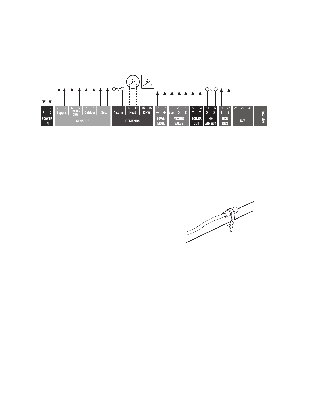
Fig. 5. Low voltage wiring for the AQ15200B Control Module.
TO BOILER SUPPLY SENSOR
TO BOILER RETURN SENSOR
TO OUTDOOR SENSOR
TO SECONDARY SENSOR
IN FROM “R” TERMINAL ON
TRANSFORMER MODULE
(FACTORY-WIRED)
TO “T-T” TERMINALS ON
BOILER AQUASTAT
TO B-B “EXP.BUS IN”
TERMINALS ON CONNECTED
ZONING MODULE
TO SETPOINT LOAD
(OPTIONAL)
TO DHW AQUASTAT
TO MODULATING MIXING VALVE
OR VARIABLE SPEED PUMP
TO FLOATING
ACTION MIXING
VALV E
IN FROM “C” TERMINAL
ON TRANSFORMER MODULE
(FACTORY-WIRED)
TO LOW VOLTAGE AUXILIARY
DEVICE (OPTIONAL)
TO AUXILIARY INPUT
SWITCH (OPTIONAL)
M27685A
M13763
Temperature Sensor Wiring
Connect the lead wires of each sensor to the corresponding
terminals on top of the AQ1520 Control Module. See Fig. 5.
The Boiler Supply, Return and Secondary loop sensors can be
installed either as strap-on sensors or inserted into an
immersion well that is packed with thermally-conductive paste.
BOILER SUPPLY AND RETURN SENSORS.
Both the Supply and Return Sensors should be installed on the
supply and return piping of the boiler for proper operation of the
AQ252 Control Panel. Even if the AQ252 is connected to a
modulating condensing boiler with its own supply and/or return
sensors, the AQ252’s sensors should still be installed for the
control to operate.
The Boiler Supply water sensor should be installed on the
supply piping close to the exit port of the boiler, using one of
the AQ12C11 strap-on sensors supplied with the AQ252. See
Fig. 6 on page 8.
The Boiler Return sensor should be installed on the return
piping as close to the entrance port to the boiler as practical,
using the other AQ12C11 strap-on sensor supplied with the
AQ252.
The correct location is one that will measure the temperature of
all combined sources of water returning back to the boiler.
Insulate strap-on sensors with pipe wrap to ensure accurate
boiler temperature sensing.
The Boiler Supply and Return water sensors come with 10 ft.
(3m) of wire to minimize the need for splicing.
SECONDARY (MIXED) LOOP SUPPLY SENSOR
The secondary sensor should be installed on the secondary
(mixed) water piping, far enough downstream of the mixing
device that the return water from the mixed loop and the boiler
loop water are sufficiently well mixed, but before it flows
through a branch leading to a zoning pump, zoning valve or
manifold. The sensor used for the secondary loop is the same
type of sensor (AQ12C11) as the Boiler Supply and Return
sensors. See Fig. 6.
Fig. 6. Strap-on temperature sensor installation.
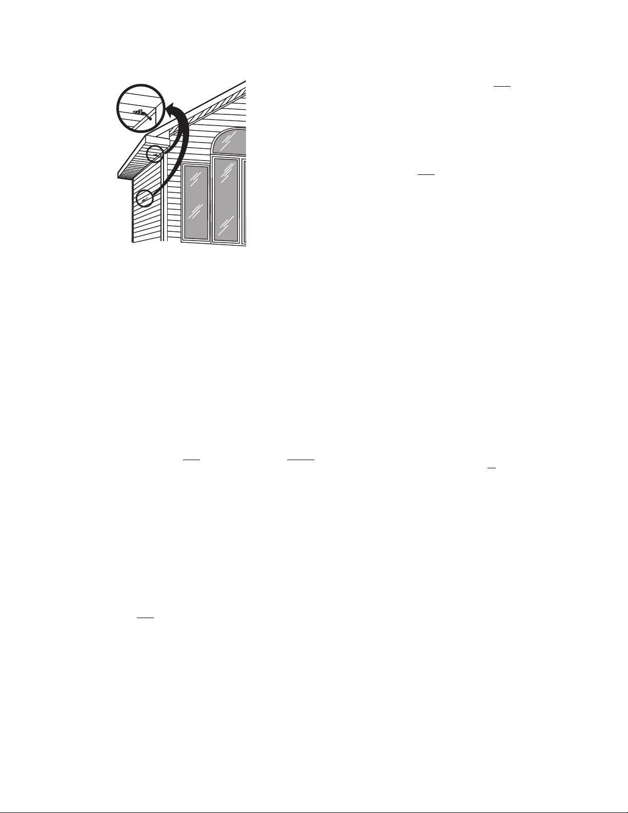
OUTDOOR SENSOR
The outdoor sensor should be located:
• in a shady location out of direct sunlight
• at least three feet from dryer, bathroom, or other vents
• above the expected snow line where ice and debris cannot
cover it
• on the north side of the building.
See Fig. 7 on page 9 for typical placement. Outdoor sensor
comes with 10 ft. (3m) of wire to facilitate splicing the sensor on
the interior of the building. Alternatively, if the building is
equipped with a continuous fresh air supply using, for example,
an air-to-air heat exchanger, the outdoor sensor may be
installed in the insulated portion of the ventilation intake duct,
taking care not to expose the sensor to direct or indirect
sunlight.
69-1986—05 8
SETUP > ZONING > HEAT DMND selection (see Fig. 25 on
M13775
page 42). Heat Demand priority allows only
heat for the first 30
minutes of a call for heat and then allows the space heating
needs to be added in for the next 30 minutes. This cycle
continues until the call for heat is satisfied.
DOMESTIC HOT WATER
Wire the DHW (terminals 15 and16) to the Aquastat or
thermostat on the domestic hot water tank.
Fig. 7. Outdoor temperature sensor installation.
IMPORTANT
Do not run sensor wires parallel, or close, to
telephone, Ethernet, or power cables. Cross all
power, Ethernet, and telephone wiring at right angles.
If sensor wires are located in an area with strong
sources of electromagnetic interference, or EMI, (e.g.,
if sensor wires are run in the same electrical chase as
line voltage wiring) use twisted pair, shielded cable, or
run wires in a grounded metal conduit.
This is important because the calculated temperature
- based on the sensor's resistance reading - can be
distorted by high EMI, potentially causing the AQ252
to not operate properly.
If using shielded cable or conduit, connect the shield
wire to earth ground only
at the AQ252 panel. Do not
ground the shield or conduit at any other location or
electromagnetic shielding will be ineffective. If
shielded cable is used, Honeywell recommends the
use of shielded cable with a continuous ground plane,
such as foil, with an integral drain wire for bonding to
earth ground.
System Demands Wiring
Additional information about settings for the various System
Demands is discussed in Table 6 on page 33.
AUX-IN
If the optional Aux In. contacts (terminals 11 and 12) will be
used, wire them now. These inputs are powered with 24 Vdc
and must connect only
switch).
The Aux-In contact closure sets the system into a specific
state, as determined by the installer setup using the
EQUIPMENT SETUP > AUXILIARY I/O sub-menu (see
Fig. 25 on page 42).
HEAT DEMAND
If the optional Heat Demand (terminals 13 and 14) will be used,
wire them to a system setpoint demand (dry contact closure),
such as a pool or spa Aquastat®.
The HEAT contact closure drives the system to control either at
the Reset temperature or the Setpoint temperature, as
determined by the installer setup using the EQUIPMENT
to a dry closure contact (unpowered
DHW priority allows only
DHW heat for the first 30 minutes of a
call for DHW and then allows the space heating needs to be
added in for the next 30 minutes. This cycle continues until the
call for DHW is satisfied.
NOTE: If the AQ252 is connected to a modulating
condensing boiler with built-in DHW
management, the DHW tank’s Aquastat should be
connected to the AQ252's DHW (terminals 15 and
16). The AQ252's Aux. Out (terminals 24 and 25)
should be wired to the boiler's DHW input
terminals to the AQ252.
Low Voltage Outputs Wiring
10 VDC
The 10 Vdc terminals (17 and 18) of the AQ252 produce a
modulating (0-10 Vdc or 2-10 Vdc) signal that can drive a
modulating boiler’s combustion fan or a modulating mixing
device, such as a motorized mixing valve or a variable-speed
injection pump.
Boiler Signal: If the AQ252 panel is configured to send a
0-10V or 2-10V signal to a modulating/condensing
boiler, connect the AQ252’s modulating output terminals
(17 and 18) to the modulating signal input on the boiler
control.
Secondary Loop Control: If a 0-10V or 2-10V driven
variable speed injection pump or
valve is used for controlling the temperature of the
secondary loop, wire the mixing device to the - and +
terminals (17 and 18) of the AQ252.
FLOATING ACTION OUTPUT
Floating action valve: If a floating action valve is used for
controlling the temperature of the secondary (mixed)
loop, wire the Common (Com), Open (O), and Close (C)
(terminals 19, 20, and 21) of the AQ252 to the
corresponding terminals on the mixing valve’s actuator.
BOILER
Wire the Boiler dry contact output (terminals 22 and 23) to the
T-T terminals on the boiler Aquastat or the boiler's control
panel. See Fig. 15 on page 13 for wiring connections to a
typical boiler Aquastat.
These contacts are made any time the system has a request
for boiler operation, unless the water supply temperature is
above the target temp at that time. If this occurs, the system
primary boiler pump would come on.
AUX-OUT
If the Auxiliary Out low voltage output will be used, wire it now
to the device (e.g., A/C compressor) that will be switched when
the Auxiliary Out’s dry contacts close. Wire the hot leg of the
device through the Aux. Out connection (terminals 24 and 25).
a modulating mixing
9 69-1986—05
The Aux-Out relay contacts close to correspond with an action,
Zone 1
Zone 2
Zone 3
Zone 4
Zone 1
Zone 2
Zone 3
Zone 4
M27686A
DATA BUS
COMMUNICATION
WIRING
AQ25744B
AQ25242B
as determined by the installer setup using the EQUIPMENT
SETUP > AUXILIARY I/O sub-menu (see Fig. 25 on page 42).
features that depend on this networked communication (e.g.,
zone synchronization, outdoor temperature displayed on
thermostats, etc.) will not function.
NOTE: The Aux. Out contacts are rated for low voltage
devices only.
Communication Bus Wiring
All AQ2000 components communicate with each other on the
AQUATROL network using communication bus wiring. This
wiring must connect all AQ2000 components. Otherwise,
Fig. 8. Wiring for communication bus.
The communication bus wiring is polarity insensitive. The
installer does not need to worry about a +ve or –ve orientation
of the wires. If there are two wires connected between the B-B
Bus Exp. In on one module and B-B Bus Exp. Out on another
module, there will be communication. See example in Fig. 8 for
how this wiring is to be installed.
The communication bus connections for AQ252 Control Panels
are pre-wired at the factory.
Step 3 – Thermostats Wiring
NOTE: The new AQ2000 panels will work with either digi-
tal (electronic) non-communicating thermostats
or AQ1000 communicating thermostats.
1. Using low voltage thermostat wire, connect one thermo-
stat from each zone to the corresponding THERMOSTATS Zone X inputs on top of the Zoning Module (see
Fig. 9).
2. If there are additional zones (on Expansion Zoning
Panels) connected to this Zoning Module, run low
voltage thermostat wiring from the B-B Exp. Bus Out
connection (terminals 13 and 14) of the Zoning Module
to the B-B Exp. Bus. In connection (terminals 3 and 4) on
the Expansion Zoning Panel.
IMPORTANT
Do not run thermostat wires parallel, or close, to
telephone, Ethernet, or power cables. Cross all
power, Ethernet, and telephone wiring at right angles.
If thermostat wires are located in an area with strong
sources of electromagnetic interference, or EMI, (e.g.,
if thermostat wires are run in the same electrical
chase as line voltage wiring) use twisted pair,
shielded cable, or run wires in a grounded metal
conduit.
This is important, because the AQ1000 thermostats
are communicating thermostats which send and
received data via the two wires connecting them to
the Zoning Module. This data can be distorted by the
EMI, potentially causing the AQ252 to not operate
properly.
3. Run low voltage thermostat wiring from the R and C
output terminals on the secondary of the AQ252 Control
Panel’s transformer to the R and C input terminals on the
Expansion Zoning Panel. As an alternative, you can run
low voltage thermostat wiring from the R and C terminals
on the Zoning Module to the R and C terminals on the
Expansion Zoning Panel.
THERMOSTAT ON ZONE 1
THERMOSTAT ON ZONE 2
THERMOSTAT ON ZONE 3
FROM B-B “EXP. BUS”
TERMINALS ON
CONTROL MODULE
THERMOSTAT ON ZONE 4
TO B-B “EXP. BUS IN” TERMINALS
ON CONNECTED ZONING MODULE
Fig. 9. Connecting thermostats.
Step 4 – Zoning Equipment Wiring
Because the Zoning Module of the AQ25242B Control Panel
can be used with either line voltage pumps or valves, or low
voltage zone valves (with or without end switches), field
(IF AN EXPANSION ZONING PANEL
IS CONNECTED)
M13776C
69-1986—05 10
installed wiring of the correct voltage needs to be connected to
FROM LINE VOLTAGE
120V TERMINALS
(N AND L) ON BOTTOM
OF TRANSFORMER
M27687A
M27688A
FROM LOW VOLTAGE
24 VAC TERMINALS
(C AND R) ON TOP
OF TRANSFORMER
M M M M
M27689A
M
M27690A
M
M
M
the zoning equipment terminals on the bottom left portion of
the Zoning Module.
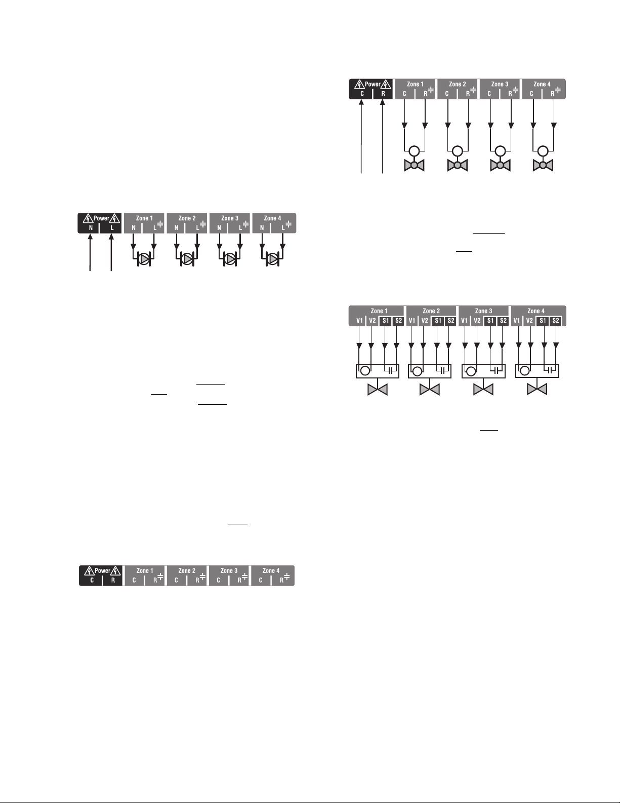
Line Voltage – Circulators or Zone Valves
Refer to Fig. 10. Remove the plastic wiring barrier that is
located in the bottom wiring channel between the AQ15200B
Control Module and the Zoning Module. Run jumper wires from
the N and L terminals on the bottom of the AQ252 Control
Panel’s transformer, through the wiring channel across the
bottom of the Control Panel, and to the corresponding N and L
terminals of the Zoning Module.
Fig. 10. Wiring an AQ15540B Zoning Module for use
with line voltage circulators.
Low Voltage – Zone Valves With or Without
End Switches
Wire using step 1 for zone valves without end switches, or use
step 2 for zone valves with
• Low voltage zone valves without
Using Fig. 12 on page 11 as a guide, run jumper
wires from the R and C terminals on the secondary of
the AQ252’s transformer, through the wiring channel
across the top of the Control Panel, and down through
the wiring channel on the right side of the panel and
over to the R and C terminals on the bottom of the
Zoning Module.
IMPORTANT
If low voltage zone valves are used with the
AQ25242B Control Panel, the supplied Low Voltage
Output sticker (shown in Fig. 11) must
the line voltage output sticker (see Fig. 10) that is
already attached to the Zoning Module.
Fig. 11. Low voltage output sticker.
end switches:
end switches:
be applied over
Fig. 12. Wiring an AQ15540B Zoning Module for use
with low voltage zone valves without
end switches.
4. Low voltage zone valves with end switches:
See Fig. 13. 24 Vac power is pre-wired between the
transformer secondary at the top left of the AQ252’s
transformer and the AQ15740B Zoning Module. No field
wiring is required.
Fig. 13. Wiring an AQ15740B Zoning Module for use
with low voltage zone valves with
end switches.
NOTE: When wiring zone valves with end switches, note
the transformer's VA:
If low voltage zone valves with end switches are
used for zone control, make sure the selected
zone valves do not draw more power (VA) than the
38 VA capacity of the AQ10X38 transformer
supplied with the AQ252 Control Panel. This
integral transformer has enough power to operate
4 motorized zone valves (such as Honeywell
V8043E valves or 4 valves using low-amperage
draw, heat motor actuators, such as Honeywell
MV100 actuators), plus power the electronics of
the AQ252's Control Module and up to 16 AQ1000
thermostats. If zone valves with high-amperage
draw heat-motor actuators are used (such as Taco
500 series zone valves), additional 24 Vac
transformer capacity will need to be wired to the
Zoning Module to power the valves. See
Fig. 14 on page 12 for recommended wiring of
additional low voltage VA capacity to AQ2000
Series Zoning Modules.
11 69-1986—05
CAUTION
THERMOSTATS
ZONE 1 ZONE 2 ZONE 3
ZONE 4
M27691A
THERMOSTATS
ZONE 1 ZONE 2 ZONE 3
ZONE 4
Zone 1
Zone 2
Zone 3
Zone 4
USING AN AQ15740B
VALVE ZONING MODULE
POWER SUPPLY. PROVIDE DISCONNECT MEANS AND OVERLOAD PROTECTION AS REQUIRED.
1
Zone 1
Zone 2
Zone 3
Zone 4
1
2
3
1
2
3
1
2
3
1
2
3
1
2
3
1
2
3
1
2
3
1
2
3
24 VAC
100 VA
TRANSFORMER
115 VAC
115 VAC
24 VAC
100 VA
TRANSFORMER
1
1
USING AN AQ15540B
PUMP ZONING MODULE
Equipment Damage Hazard.
Can damage internal circuitry of Zoning Module.
The ES1 and ES2 terminals of the AQ15740B Zoning
Module are powered terminals and must only
be
connected to a set of dry contacts, such as a zone
valve motor's end switch. If power is applied to these
contacts (for example, by running line voltage through
the zone valves’ end switches to bring on a circulator
feeding those valves), the internal circuitry of the
Zoning Module will be damaged, in which case the
warranty for this product will be voided.
69-1986—05 12
Fig. 14. Wiring of additional low voltage VA capacity.
Step 5 – Line Voltage System Outputs
ZC
ZR
B1
B2
C1
C2
L1
L2
TT
G
L8148, L7148
R8184A, R7184
BURNER AND
IGNITION
C554
F
F
T
T
BLACK
WHITE
ORANGE
POWER SUPPLY. PROVIDE DISCONNECT MEANS AND OVERLOAD PROTECTION AS REQUIRED.
L1
(HOT)
L2
1
1
TO AUXILIARY DEVICE
(INSTALLER-DEFINED)
BOILER
PUMP
M27692A
N
L
TO LINE VOLTAGE 120V
TERMINALS (N AND L) ON
BOTTOM OF TRANSFORMER
FROM LINE VOLTAGE 120V
TERMINALS (N AND L) ON
BOTTOM OF TRANSFORMER
TO BOILER
TERMINALS 22-23
ON TOP OF AQ15200B
CONTROL MODULE
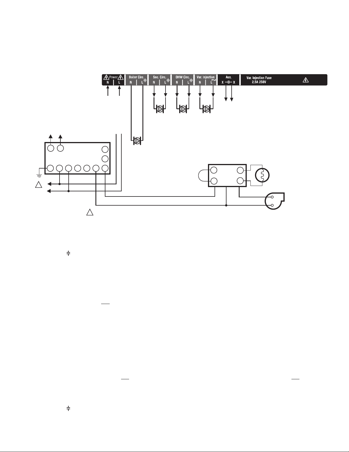
Refer to Fig. 15 and follow these steps to wire the devices to
the AQ252 Control Module.
“1. Boiler Pump”
“2. DHW Device”
“3. Line Voltage Rated Variable Injection Pump”
“4. Line Voltage Rated Aux Output (Aux. Pump)” on page 14
“5. Secondary Pump” on page 14
1. Boiler Pump
Connect the N and L wires of the boiler loop pump to the N and
switched hot ( ) terminals of the line voltage Boiler output,
shown in Fig. 17 on page 14. The ground wire of the pump can
be connected to any of the 8 ground screw terminals located
on the back surface of the Control Panel enclosure.
The boiler pump contacts are made after any one of the
following occur:
• A call for heat has occurred from any heating zone.
• The Heat input is shorted on terminals 13 and 14.
• The DHW input is shorted and
The pump is delayed for the FIRE DELAY programmed in the
EQUIPMENT SETUP > BOILER OPERATION sub-menu (see
Fig. 25 on page 42). The boiler pump and the last zone calling
remain “On,” in order to move heat out of the boiler for the
period of time programmed in the Purge time menu under the
fire delay. Manually adjusting thermostats affects the operation
of this software, so it can not be tested manually. You must
observe it under normal operating conditions.
NOTE: If the AQ252 is connected to a modulating
Fig. 15. Line Voltage Connections for AQ252.
the DHW type is configured
as a valve.
condensing boiler, the boiler pump may need to
be connected to the boiler, not
Confirm this with the boiler’s installation manual.
the AQ252.
If using a low voltage zone valve, wire the primary of a spudmounted transformer (115V to 24V) to the DHW line voltage
contacts and connect the low voltage zone valve to the
secondary terminals of this transformer. A spud-mounted
transformer may be located in one of the conduit knockouts on
the bottom of the AQ252 Control Panel.
Alternatively, a 24 Vac zone valve can be connected to the Aux.
pump line voltage-rated dry contacts, which can be configured
to close on a DHW call. This configuration is defined in the
Installer Equipment Setup menu beginning on page 33.
The DHW contacts are made when the DHW inputs on
terminals 15 and 16 are shorted by the controlling Aquastat.
This is a line voltage output designed to go to the DHW pump.
If 24 Vac is needed for a low voltage valve, you can mount a
step-down transformer on the conduit opening and wire the
valve from the transformer. When DHW is enabled, the system
has a 30 minute priority over all calls for heat. After 30 minutes,
calls for heat are added back in to the operation for 30 minutes
and then turned off again. This repeats until the DHW is
satisfied.
NOTE: If the AQ252 is connected to a modulating
condensing boiler, the DHW pump will probably
need to be connected to the boiler, not
the AQ252.
Confirm this with the boiler’s installation manual.
2. DHW Device
Wire the DHW pump or line voltage zone valve to the N and
switched hot ( ) terminals of the DHW output, as shown in
Fig. 17 on page 14.
3. Line Voltage Rated Variable Injection
Pump
The terminals for the variable injection pump are line voltage
rated and protected by an external fuse. A standard pump is
controlled by the output of these terminals.
13 69-1986—05
Setup is enabled in the EQUIPMENT SETUP > SECONDARY
BY-PASS PUMP
M27693A
TO AUXILIARY DEVICE
(INSTALLER-DEFINED)
FROM LINE VOLTAGE
120V TERMINALS
(N AND L) ON BOTTOM
OF TRANSFORMER
M27694A
LOOP sub-menu when the INJECT parameter is set to
ENABLE (see Fig. 25 on page 42). The pump remains off
(drive is off) whenever the Return temperature is below the
Boiler Minimum Return temperature.
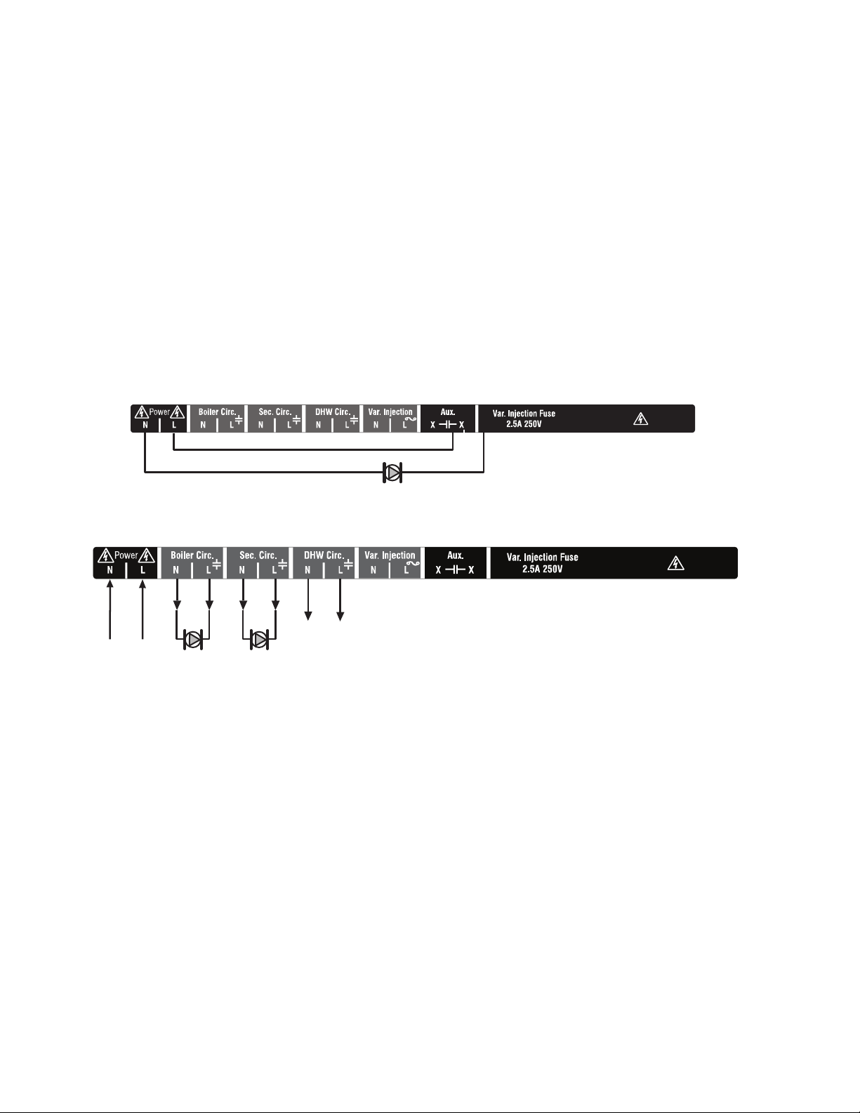
4. Line Voltage Rated Aux Output (Aux.
Pump)
To connect a line voltage auxiliary device to these contacts,
such as a group pump or a boiler bypass pump, power the
device from the N and L terminals on the bottom of the Control
Module, running the hot (L) lead through the Aux. Pump
contacts. See Fig. 16 for details. The exact wiring schematic
will depend on what is connected to these dry contacts.
The Aux Pump is a line voltage rated dry contact that is
controlled by the selection in the EQUIPMENT SETUP >
AUXILIARY I/O sub-menu (see Fig. 25 on page 42).
NOTE: Use of this output is optional. The Aux. pump dry
contacts are line voltage-rated but unpowered. A
low voltage device can be connected to these programmable contacts, but the wire's insulation
must meet applicable codes for use in line voltage
enclosures.
See page 33 for programming options for the Aux.
Pump dry contacts.
5. Secondary Pump
Connect the N and L wires of the secondary (mixed) loop
pump to the N and switched terminals of the line voltage Sec.
output. shown in Fig. 17. The ground wire of the pump can be
connected to any of the 8 ground screw terminals located on
the back surface of the Control Panel enclosure.
The secondary pump terminals energize only when a zone that
has been designated as a secondary zone has a call for heat.
This enables the pump and the mixing device you have chosen
for the loop control. Set-up is enabled in the EQUIPMENT
SETUP > PRI/SEC sub-menu (see Fig. 25 on page 42).
Fig. 16. Wiring of the Aux. pump line voltage rated dry contacts (example shown is a by-pass pump).
Fig. 17. Wiring for Boiler Pump, Secondary (Mixed) Loop Pump, DHW Device, Injection Pump, and Aux Output.
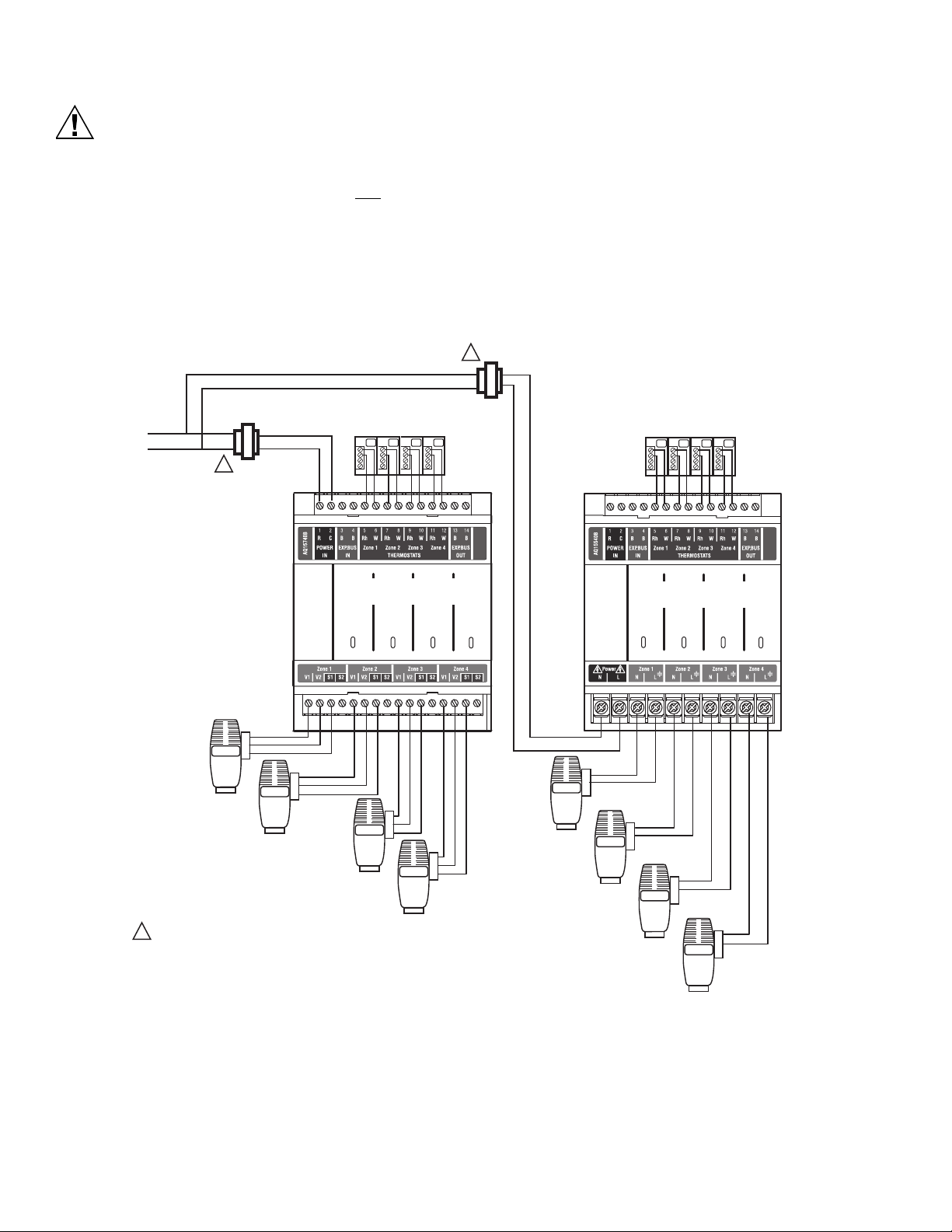
Step 6 – Connection To Line Voltage Power
Connect the N and L line voltage inputs of the primary on the
AQ252 transformer to the electrical distribution panel and
power up the Control. A service switch should be installed on
If multiple Zoning Modules are connected to the AQ252 Control
Panel, the line voltage wiring can either be run directly from the
N and L terminals on the primary of the transformer to each
Zoning Module (Fig. 18), or run in a daisy chain from the N and
L terminals of one AQ2000 module to the N and L terminals of
the next AQ2000 module (see Fig. 19 on page 15).
the hot (L) lead to the distribution panel.
69-1986—05 14
 Loading...