

Page 1
68-0306-05
AQ250 Series Hydronic Control Panels
Need new photo of AQ250
PRODUCT DATA
PRODUCT DESCRIPTION
The AQ250 easily converts a single-zone heating system into
a room-by-room comfort control system, or upgrades a basic,
relay-logic zoning system to intelligent Zone of Greatest
Demand control. The boiler control of the AQ250 can ensure
ample supply of hot water for both space heating and priority
generation of domestic hot water for bathing, dishes and
laundry.
FEATURES
The AQ250 Series Hydronic Control Panels have the following
features:
• Zoning Control for up to four, single-stage zones or
two, two-stage zones as shipped; can be expanded to
a total of 16 zones with AQ255 or AQ257 expansion
zoning panels, and up to 64 zones by us ing up to thre e
AQ254 Add-a-Temperature expansion panels and
additional expansion zoning modules.
• Controls one boiler loop.
• Zone synchronization through Zone of Greatest
Demand control.
• Domestic hot water (DHW) priority and priority
override protection.
• Use with digital non-communicating thermostats or
AQ1000 2-wire polarity insensitive communicating
thermostats.
• Automated test feature for quick start-up and
simplified troubleshooting.
• Boiler freeze protection (in the event of network
communication failure).
• Boiler short cycling protection, post purge, and shock
prevention from cold water returning to boiler.
• Line or low-voltage output for zoning equipment
(pumps or valves).
• Integral 38 VA transformer with self resetting
electronic fuse.
IMPORTANT
T o ensure correct installation and proper operation of
the control, perform the 7 installation steps in the
order numbered in the “Contents” below.
Contents
Specifications ................................................................... 2
1 Installation Preparation .................................................. 3
2 Mounting ........................................................................ 4
3 Wiring Procedure ........................................................... 5
4 Configure the Control Panel DIP Switches .................... 14
5 Test and Check Out the Installation ............................... 17
6 Purge Air from all System and Zone Piping .................. 19
7 Document and Keep a record of all System Settings .... 19
Troubleshooting ................................................................ 19
Page 2

AQ250 SERIES HYDRONIC CONTROL PANELS
• When using non-communicating thermos tats, the
following features are not available:
• Outdoor temperature is not displayed on the
thermostat.
• Individual zone freeze protection.
SPECIFICATIONS
The AQ250 Control Panels and corresponding attached
equipment are listed in Table 1.
Table 1. AQ250 Series Control Panel Models.
Control Panel
AQ25042B AQ15000B AQ15540B
AQ25044B AQ15000B AQ15740B
Application: Controls one boiler loop as well as domestic hot
water (DHW) management and zoning operation in a
hydronic zoning system.
Power and Electrical Ratings:
Power Supply: 120 Vac / 60Hz
Auxiliary Pump Contact Rating: 120/250 Vac, 5A,
1/3 HP
Boiler (T-T) Contact Rating: 24 Vac, 0.5A, 12 VA
Boiler Pump Output Rating: 120 Vac, 5A, 1/3 HP
DHW Pump/Valve Output Rating: 120 Vac, 5A, 1/3 HP
B–B Communication Bus Terminals: Low voltage,
Class II, 2-wire polarity-insensitive, digital
communicating link to other Control or Zoning modules.
Electrical Connections (Line Voltage): Wire-clamp
screw terminals; maximum 2 x 14 AWG each on line
voltage terminals
Environmental Ratings:
Control and Zoning Panel Temperature Rating: 32°F to
130°F (0°C to 55°C)
Corresponding
Control Module
Corresponding
Zoning Module
Operating Humidity Range (% RH): 5 to 90% RH, non-
condensing
Temperature Ratings:
Return Minimum Control Temperature: 140°F (60°C);
This is the temperature at which the bypass pump
(Aux. Pump contacts) is activated.
Sensor Temperature Rating: -58°F to 230°F (-50°C to
110°C)
Inputs/Outputs:
DHW Demand Input: External dry contacts connection
only
Heat Demand (Thermostat R-W) Input: External dry
contacts connection only
R–C Input (on Control and Zoning Modules): 24 Vac
Class II
R–C Output (on transformer): 38 VA, 24 Vac Class II
Interface and Timings:
User Interface: DIP Switch settings
Boiler Heat Post Purge: 30 seconds; not adjustable
Pump/Valve exercise: 30 seconds per 2 weeks of space
heating inactivity; not adjustable
Thermostat Compatibility: Digital thermostats and/or
AQ1000 Series 2-wire communicating thermostats
Supply/Return Loop Sensor: 10K ohm NTC thermistor at
77°F (25°C) ± 0.5°F (±0.3°C). Lead length: 10 ft. (3.0 m);
up to 500 ft. (150 m) using 18 AWG or larger wire,
beta=3892.
Dimensions (HxWxD): 8.0 x 13 x 3.3 in. (20.3 x 32.9 x
8.5 cm) approximate
Weight: 4.9 lb. (2.2 kg)
Approvals: Canadian Standards Association: Certified, File
No. LR76030
ORDERING INFORMATION
When purchasing replacement and modernization products from your TRADELINE® wholesaler or distributor, refer to the
TRADELINE® Catalog or price sheets for complete ordering number.
If you have additional questions, need further information, or would like to comment on our products or services, please write or
phone:
1. Your local Honeywell Automation and Control Products Sales Office (check white pages of your phone directory).
2. Honeywell Customer Care
1885 Douglas Drive North
Minneapolis, Minnesota 55422-4386
In Canada—Honeywell Limited/Honeywell Limitée, 35 Dynamic Drive, Toronto, Ontario M1V 4Z9.
International Sales and Service Offices in all principal cities of the world. Manufacturing in Australia, Canada, Finland, France,
Germany, Japan, Mexico, Netherlands, Spain, Taiwan, United Kingdom, U.S.A.
68-0306—05 2
Page 3

AQ250 SERIES HYDRONIC CONTROL PANELS
WARNING
1 INSTALLATION PREPARATION
NOTES: Through out these instructions, the following
terminology conventions are used:
— AQ150 refers to the AQ15000B Control Module;
— AQ155 refers to the AQ15540B Zoning Module.
— AQ157 refers to the AQ15740B Zoning Module.
— AQ250 is used when the information applies to both
the AQ25042B and AQ25044B Control Panels. Where
there are specific instructions or details relating to the “42B” or “-44B” Control Panels, the full model number
(i.e. AQ25044B) is used;
— AQ255 refers to all of the AQ25542B, AQ25582B and
AQ25742B Expansion Zoning Panels
— AQ257 refers to the AQ25744B Expansion Zoning
Panel. Where there are specific instructions or details
relating to the “-42B”, “-82B”, “-42B”, or “-44B”
Expansion Zoning Panels, the full model number (i.e.
AQ25744B) is used;
— Control Module refers to the component within an
AQ2000 Series Control Panel that performs the master
control operations. See Table 1 on page 2 for specific
models.
— Control Panel refers to an assembled product,
consisting of a transformer, Control Module and Zoning
Module, all contained within an AQ2000 panel
enclosure;
— Expansion Zoning Panel refers to an assembled
product, consisting of a Zoning Module and, if
applicable, a transformer, contained within an AQ2000
panel enclosure. Zoning Modules are available in either
4-zone or 8-zone configurations. Refer to Honeywell
literature Form No. 69-1981 for more information on
these products.
— Zoning Module refers to the component within an
AQ2000 Series Control Panel or Zoning Expansion
Panel.
When Installing this Product…
1. Read these instructions carefully. Failure to follow
them could damage the product or cause a
hazardous condition.
2. Check the ratings given in the instructions and on
the product to make sure the product is suitable for
the application.
3. Installers must be trained, experienced, and licensed
service technicians.
4. Follow local codes for installation and application.
5. After installation is complete, check out the product
operation as printed in these instructions.
Risk of electrical shock.
Can cause severe injury, property damage or death.
Disconnect power supply before installation and before
servicing.
Check That You Have All the Necessary
Equipment For a Successful Installation
• AQ2000 Series components:
— AQ250 Control Panel
— AQ Expansion Zoning Panels (if more than four space
heating zones in the system)
— Digital thermostats (one for every space heating zone
being controlled)
• Boiler supply and return temperature sensors (included with
the AQ250 Control Panel)
• Low voltage thermostat wire
• Zoning equipment (zone valves or pumps)
Read All Instructions Carefully Before
Proceeding
The AQ250 Control Panels are a part of a totally new series of
hydronic controls. And although they - and other AQ2000
system components - are very easy to install and operate, they
are different than other hydronic controls that you have
previously installed. So take a moment to read through this
quick installation guide before
Failure to follow them could damage the product or cause a
hazardous condition.
beginning the installation.
Familiarize Yourself With the AQ250 Control
Panel Layout
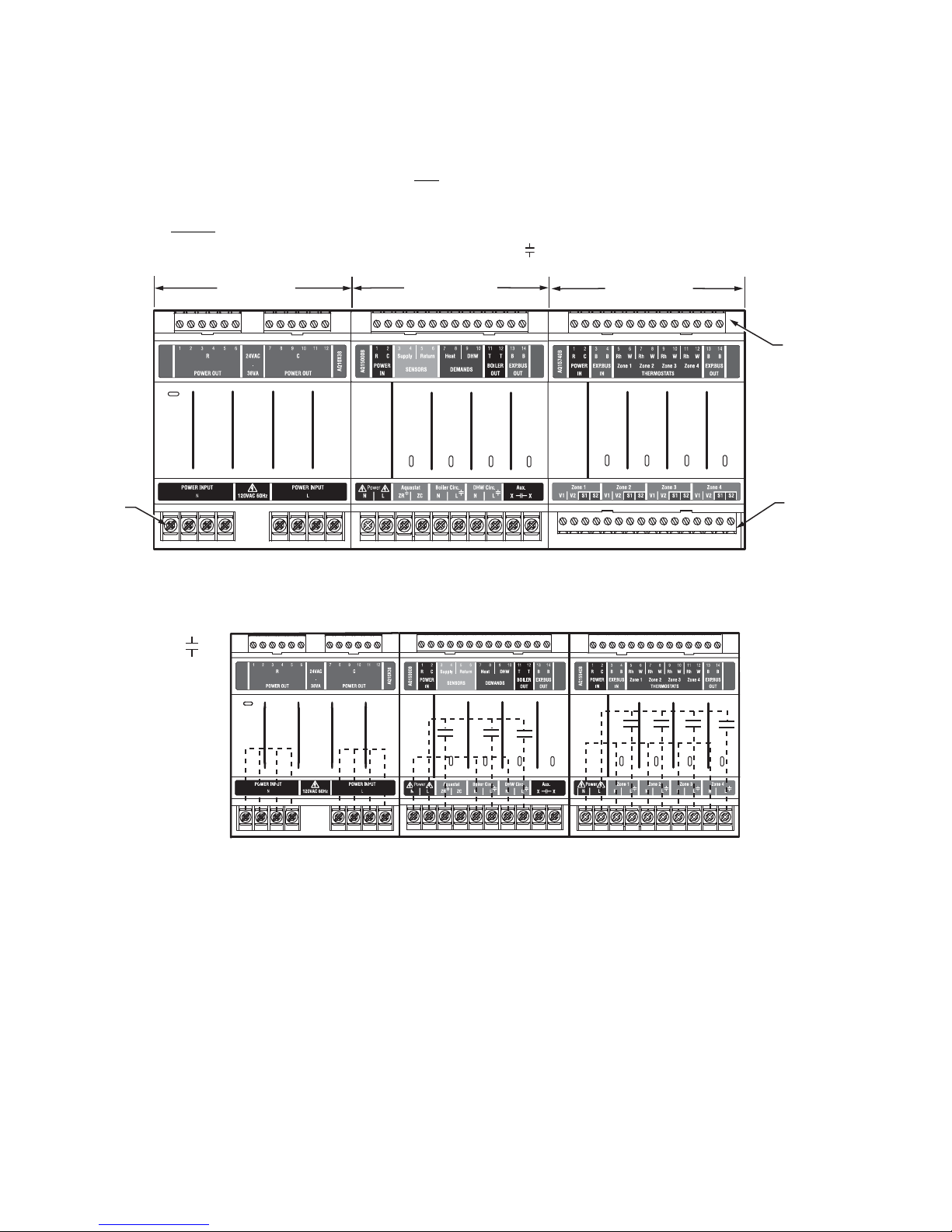
Refer to Fig. 1 on page 4. All AQ250 Control Panels consist of
three functional components:
1. AQ10X38 transformer (power supply module), which
connects to 120 V ac power and supplies 24 V ac power to
the Control Module and Zoning Modules
2. AQ15000B boiler / DHW Control Module, which controls
the boiler and domestic hot water (DHW) functions as
well as coordinating the overall operation of the hydronic
system.
3. One of two different 4-zone Zoning Modules:
• AQ15740B (part of the AQ25044B Control Panel)
for zoning with 24 Vac zone valves with
switches.
• AQ15540B (part of the AQ25042B Control Panel)
for zoning with either line voltage circulators or 24
Vac zone valves without
AQ250 Control Panels can control a maximum of 16 zones by
connecting additional Expansion Zoning Panels to the AQ250
Control Panel. Each Expansion Zoning Panel is configured
with its own bank of DIP switches, located in the left-most
section of each Zoning Module. To expand the capacity of an
AQ250 Control Panel beyond 16 zones, an AQ254 Add-ATemperature Expansion Control Panel is required. The
hydronic system can be expanded by 16 zones for each
AQ254 connected to the AQ2000 network. A maximum of
three (3) AQ254 Panels may be connected to an existing
AQ2000 Control Panel for a maximum of 64 zones connected
on the AQUATROL® network
NOTE: If an AQ254 Add-A-Temperature Expansion Control
Panel is used for controlling the temperature in a
mixed loop, it can reset the mixed loop temperature
using LOAD reset, but not OUTDOOR reset, as the
AQ250 panel does not have input terminals for an
outdoor sensor.
end switches.
end
3 68-0306—05
Page 4
AQ250 SERIES HYDRONIC CONTROL PANELS
A
In general, the top terminals of the AQ2000 Series components
carry low voltage (24 Vac) power and the bottom terminals
carry line voltage (120 Vac) power. This is illustrated in Fig. 1.
The two exceptions to this are:
1. AQ15740B Zoning Module for use with zone valves with
end switches.
2. AQ15540B Zoning Module when used with low voltage
zone valves without
LINE VOLTAGE
(120 V)
end switches.
TRANSFORMER
CONTROL MODULE
ZR
For these the two exceptions, the bottom terminals of the
Transformer and Control Module carry line voltage (120 Vac),
but the bottom terminals of the Zoning Module will carry low
voltage (24 Vac) power.
The powered terminals on the bottom of the AQ2000 Series
Control Modules and Zoning Modules are connected internally,
as shown in Fig. 2. The voltage supplied to the N and L
terminals is also available at the adjacent terminal pairs when
the hot ( ) relays are switched.
ZONING MODULE
Boiler
DHW
Aux
Zone 1
Zone 2
Zone 3
Zone 4
M29032A
LOW VOLTAGE
(24 V)
LOW VOLTAGE
(24 V)
Fig. 1. AQ250 Control Panel layout (AQ25044B shown).
CONTACTS
SYMBOL
Fig. 2. Internal wiring for AQ2000 Series components line voltage relays.
2MOUNTING
This section describes how to mount the Control Panel,
Expansion Zoning Panels, and the Thermostats.
Mount AQ250 Control Panel
Mount the control panel on the wall:
1. Use the template supplied with the AQ250 Series
Control Panel to mark the four mounting holes for the
panel.
2. Install two top screws, mount the panel, and install the
two lower screws.
ZR
Boiler
DHW
Aux
Zone 1
Zone 2
Zone 3
Zone 4
M29033
Mount Expansion Zoning Panels
If there are Expansion Zoning Panels to install, mount them to
the wall now:
1. Remove wire channel plugs from the AQ250 Control
Panel and any Expansion Zoning Panels (see Fig. 3 on
page 5).
2. Mount Expansion Zoning Panel on the right-hand end of
the AQ250 Control Panel. Install two top screws of the
Expansion Zoning Panel, ensuring it is level with the
adjoining Control Panel, and install two lower screws.
3. Reverse wire channel plugs and re-insert them into their
slot, to form a wiring channel between the Control Panel
and the Expansion Zoning Panel (see Fig. 3 on page 5)
and to connect the two panels together.
68-0306—05 4
Page 5
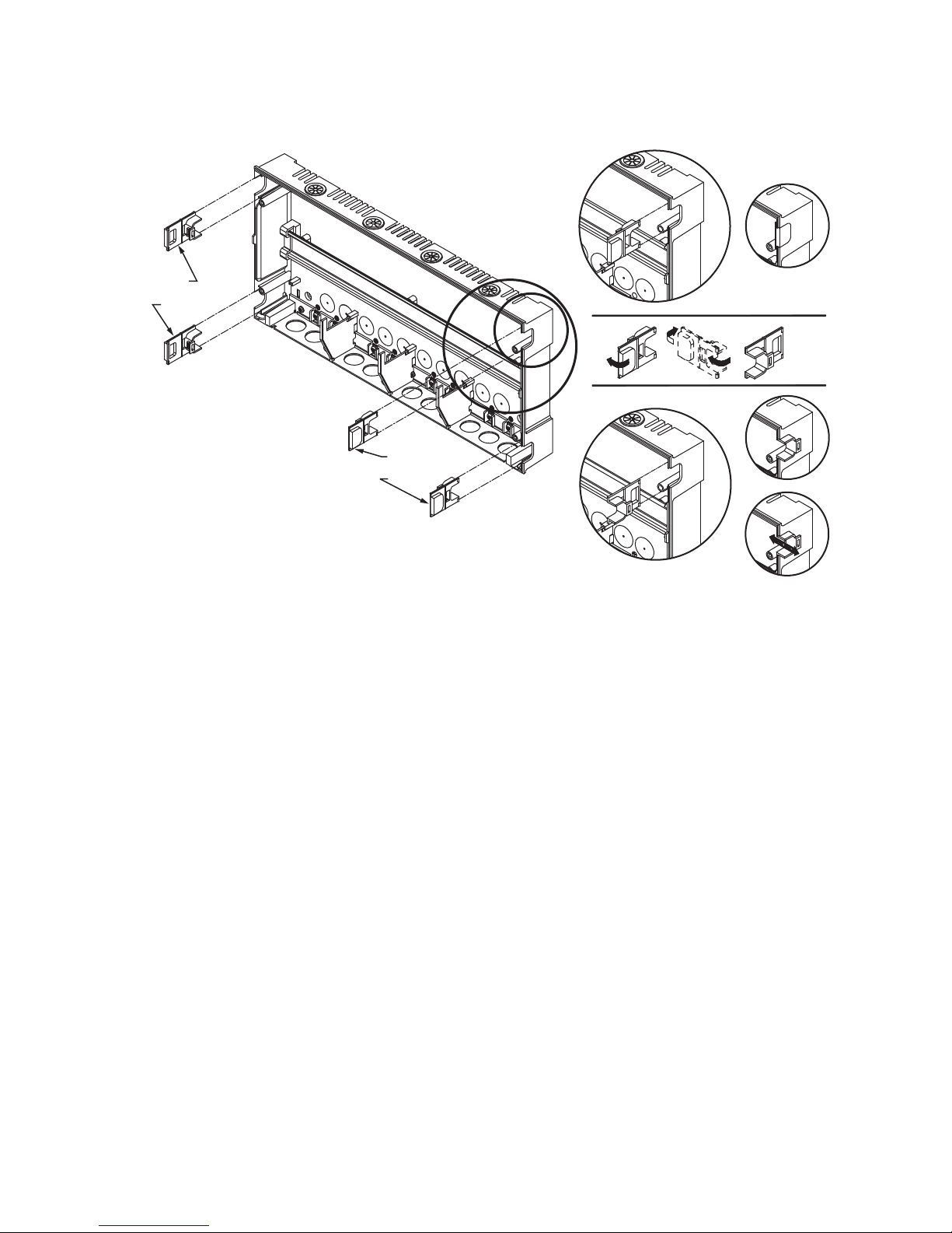
4. For any additional Expansion Zoning Panels, repeat
M23733A
WIRE
CHANNEL
PLUGS
WIRE
CHANNEL
PLUGS
steps 1–3.
AQ250 SERIES HYDRONIC CONTROL PANELS
Fig. 3. Orientation of wire channel plugs for creating pass-through wire channel and
for joining Control Panel to Expansion Zoning Panels.
Mount and Wire Thermostats in the Zones
Install the thermostats on the walls in the zones that are to be
controlled by the AQ250 Control Panel.
When using AQ1000 thermostats refer to the installation
instructions included with the AQ1000 thermostats.
If not done already, run low voltage thermostat wire (24 gauge
or heavier) from the thermostats back to the Zoning Modules
connected to the AQ250 Control Panel.
NOTES: If not otherwise specified, low voltage wiring should
be run with 18 gauge thermostat wire and line voltage
wiring should be run with 14 gauge wire. AQUATROL
line voltage screw terminals are only approved for use
with 22 to 12 gauge copper conductors.
Several wiring diagrams are included in this document. For additional information, refer to
http:// customer.honeywell.com or your local distributor.
3 WIRING PROCEDURE
The AQ250 Control Panel is pre-wired at the factory, making
for faster installation.
For all models, the low voltage output terminals located at the
top of the transformer secondary are wired to the R and C input
terminals of the Control Module, as well as the R and C inputs
of the Zoning Module. The B-B Exp. Bus terminals (13 and 14)
of the Control Module are wired to the B-B Exp. Bus IN
terminals of the Zoning Module.
Beginning with the top left of Fig. 4 on page 6 and moving
clockwise around the panel, wire components to the AQ250
Control Panel and Expansion Zoning Panels (if installed) in the
following six steps:
• “Step 1 – Transformer Wiring” on page 6
• “Step 2 – Control Panel Wiring” on page 6
• “Step 3 – Thermostats Wiring” on page 8
• “Step 4 – Zoning Equipment Wiring” on page 8
• “Step 5 – Line Volt age System Output s” on p age10
• “Step 6 – Connection To Line Voltage Power” on page 13
5 68-0306—05
Page 6
AQ250 SERIES HYDRONIC CONTROL PANELS
A
STEP 1 STEP 2 STEP 3
TO EXPANSION ZONING MODULES
(IF INSTALLED)
ZR
Fig. 4. Wiring sequence.
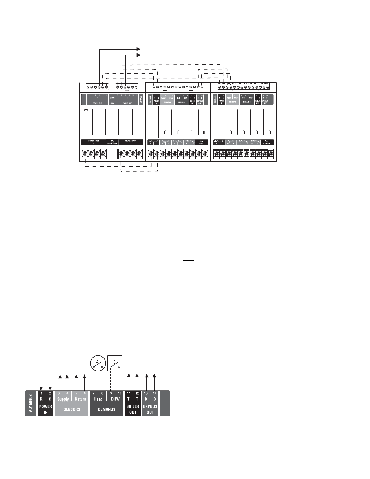
Step 1 – Transformer Wiring
Factory pre-wiring of the Control Panels is shown as dotted
lines in Fig. 4.
In addition to the pre-wiring, run low voltage jumper wires from
available R and C terminals on the secondary of the
transformer to the R and C terminals of any Expansion Zoning
Panel.
Step 2 – Control Panel Wiring
Wire the Temperature Sensors, System Demands, Low
Voltage Outputs, and Communication Bus (Refer to Fig. 5 for
wiring terminals on the top of the AQ250):
• “Temperature Sensor Wiring”
• “System Demands Wiring” on page 7
• “Low Voltage Outputs Wiring” on page 7
• “Communication Bus Wiring” on page 7
DHW
Boiler
Aux
STEP 5STEP 6
ZR Boi l er
STEP 4
Aux.
DHW
M29034
Temperature Sensor Wiring
Connect the lead wires of each sensor to the corresponding
terminals on top of the AQ15000B Control Module. See Fig. 5.
The Boiler Supply and Return sensors can be installed either
as strap-on sensors or inserted into an immersion well that is
packed with thermally-conductive paste.
BOILER SUPPLY AND RETURN SENSORS
the Supply and Return Sensors should be installed on the
Both
supply and return piping of the boiler for proper operation of
the AQ250 Control Panel. Even if the AQ250 is connected to a
modulating condensing boiler with its own supply and/or return
sensors, the AQ250’s sensors should still be installed for the
control to operate.
The Boiler Supply water sensor should be installed on the
supply piping close to the exit port of the boiler, using one of
the AQ12C11 strap-on sensors supplied with the AQ250. See
Fig. 6 on page 7.
TO DHW AQUASTAT
(OPTIONAL)
IN FROM “C” TERMINAL
ON TRANSFORMER MODULE
ON TRANSFORMER MODULE
(FACTORY-WIRED)
(FACTORY-WIRED)
IN FROM “R” TERMINAL
TO BOILER SUPPLY SENSOR
TO BOILER RETURN SENSOR
TO SETPOINT LOAD
Fig. 5. Low voltage wiring for the AQ1520M0 Control
Module.
68-0306—05 6
TO “T-T” TERMINALS ON
BOILER AQUASTAT
TO B-B “EXP.BUS IN”
TERMINALS ON CONNECTED
The Boiler Return sensor should be installed on the return
piping as close to the entrance port to the boiler as practical,
using the other AQ12C11 strap-on sensor supplied with the
AQ250. The correct location is one that will measure the
temperature of all combined sources of water returning back to
the boiler.
ZONING MODULE
Insulate strap-on sensors with pipe wrap to ensure accurate
boiler temperature sensing.
The Boiler Supply and Return water sensors come with 10 ft.
(3m) of wire to minimize the need for splicing.
M29035A
Page 7

Fig. 6. Strap-on temperature sensor installation.
M13763
Zone 1
Zone 2
Zone 3
Zone 4
ZR
Boiler
DHW
Aux
Zone 1
Zone 2
Zone 3
Zone 4
DATA BUS
COMMUNICATION
WIRING
M29036A
AQ25744B
AQ25042B
IMPORTANT
Do not run sensor wires parallel, or close, to
telephone, Ethernet, or power cables. Cross all
power, Ethernet, and telephone wiring at right angles.
If sensor wires are located in an area with strong
sources of electromagnetic interference, or EMI, (e.g.,
if sensor wires are run in the same electrical chase as
line voltage wiring) use twisted pair, shielded cable, or
run wires in a grounded metal conduit.
This is important because the calculated temperature
- based on the sensor's resistance reading - can be
distorted by high EMI, potentially causing the AQ250
to not operate properly.
If using shielded cable or conduit, connect the shield
wire to earth ground only
at the AQ250 panel. Do not
ground the shield or conduit at any other location or
electromagnetic shielding will be ineffective. If
shielded cable is used, Honeywell recommends the
use of shielded cable with a continuous ground plane,
such as foil, with an integral drain wire for bonding to
earth ground.
System Demands Wiring
HEAT DEMAND
Wire the Heat Demand (terminals 7 and 8) to a system setpoint
demand (dry contact closure), such as a pool or spa
Aquastat®.
DOMESTIC HOT WATER (OPTIONAL)
If used, wire the DHW (terminals 9 and 10) to the Aquastat or
thermostat on the domestic hot water tank.
AQ250 SERIES HYDRONIC CONTROL PANELS
DHW priority allows only DHW heat for the first 30 minutes of a
call for DHW and then allows the space heating needs to be
added in for the next 30 minutes. This cycle continues until the
call for DHW is satisfied.
NOTE: If the AQ panel is to be connected to a modulating
condensing boiler with built-in DHW management, it
is recommended to use an AQ25A or AQ251 control.
If using an AQ250 panel, it is necessary to install
DPST (Double pole, single throw) relay to clos e th e
DHW Demand on the boiler and the DHW Demand
on the AQ panel based on a call from the DHW
Aquastat.
Low Voltage Outputs Wiring
BOILER
Wire the Boiler dry contact output (terminals 11 and 12) to the
T-T terminals on the boiler Aquastat or the boiler's control
panel. See Fig. 14 on page 11 for wiring connections to a
typical boiler Aquastat.
It is not necessary to use the T-T terminals if connecting to a
Triple Aquastat, since the signal to the Aquastat is received
from the ZR/ZC terminals. See Fig. 14 and Fig. 15 beginning
on page 11 for line voltage connection to boiler Aquastats.
These contacts are made any time the system has a request
for boiler operation. When this occurs, the system’s primary
boiler pump comes on.
Communication Bus Wiring
All AQ2000 components communicate with each other on the
AQUATROL network using communication bus wiring. This
wiring must
features that depend on this networked communication (e.g.,
zone synchronization) will not function.
The communication bus wiring is polarity insensitive. The
installer does not need to worry about a +ve or –ve orientation
of the wires. If there are two wires connected between the B-B
Bus Exp. In on one module and B-B Bus Exp. Out on another
module, there will be communication. See example in Fig. 7 for
how this wiring is to be installed.
The communication bus connections for AQ250 Control
Panels are pre-wired at the factory.
connect all AQ2000 components. Otherwise,
Fig. 7. Wiring for communication bus.
7 68-0306—05
Page 8

AQ250 SERIES HYDRONIC CONTROL PANELS
FROM B-B “EXP. BUS”
TERMINALS ON
CONTROL MODULE
TO B-B “EXP. BUS IN” TERMINALS
ON CONNECTED ZONING MODULE
(IF AN EXPANSION ZONING PANEL
IS CONNECTED)
THERMOSTAT ON ZONE 1
THERMOSTAT ON ZONE 2
THERMOSTAT ON ZONE 3
THERMOSTAT ON ZONE 4
M13776C
FROM LINE VOLTAGE
120V TERMINALS
(N AND L) ON BOTTOM
OF TRANSFORMER
M29037A
M27688A
Step 3 – Thermostats Wiring
NOTE: The new AQ2000 panels will work with either digital
(electronic) non-communicating thermostats or
AQ1000 communicating thermostats.
1. Using low voltage thermostat wire, connect one
thermostat from each zone to the corresponding
THERMOSTATS Zone X inputs on top of the Zoning
Module (see Fig. 8).
2. If there are additional zones (on Expansion Zoning
Panels) connected to this Zoning Module, run low
voltage thermostat wiring from the B-B Exp. Bus Out
connection (terminals 13 and 14) of the Zoning Module
to the B-B Exp. Bus. In connection (terminals 3 and 4) on
the Expansion Zoning Panel.
IMPORTANT
Do not run thermostat wires parallel, or close, to
telephone, Ethernet, or power cables. Cross all
power, Ethernet, and telephone wiring at right angles.
If thermostat wires are located in an area with strong
sources of electromagnetic interference, or EMI, (e.g.,
if thermostat wires are run in the same electrical
chase as line voltage wiring) use twisted pair,
shielded cable, or run wires in a grounded metal
conduit.
Step 4 – Zoning Equipment Wiring
Because the Zoning Module of the AQ25042B Control Panel
can be used with either line voltage pumps or valves, or low
voltage zone valves (with or without end switches), field
installed wiring of the correct voltage needs to be connected to
the zoning equipment terminals on the bottom left portion of
the Zoning Module.
Line Voltage – Circulators or Zone Valves
Refer to Fig. 9. Remove the plastic wiring barrier that is located
in the bottom wiring channel between the AQ15000B Control
Module and the Zoning Module. Run jumper wires from the N
and L terminals on the bottom of the AQ250 Control Panel’s
transformer, through the wiring channel across the bottom of
the Control Panel, and to the corresponding N and L terminals
of the Zoning Module.
This is important, because the AQ1000 thermostats
are communicating thermostats which send and
received data via the two wires connecting them to
the Zoning Module. This data can be distorted by the
EMI, potentially causing the AQ250 to not operate
properly.
3. Run low voltage thermostat wiring from the R and C
output terminals on the secondary of the AQ250 Control
Panel’s transformer to the R and C input terminals on the
Expansion Zoning Panel. As an alternative, you can run
low voltage thermostat wiring from the R and C terminals
on the Zoning Module to the R and C terminals on the
Expansion Zoning Panel.
Fig. 9. Wiring an AQ15540B Zoning Module for use
with line voltage circulators.
Low Voltage – Zone Valves With or Without End
Switches
IMPORTANT
If low voltage zone valves are used with the
AQ25042B Control Panel, the supplied Low Voltage
Output sticker (shown in Fig. 10) must
over the line voltage output sticker (see Fig. 9) that is
already attached to the Zoning Module.
Fig. 10. Low voltage output sticker.
WIRING ZONE VALVES WITHOUT
END SWITCHES
— Using Fig. 11 on page 9 as a guide, run jumper wires
from the R and C terminals on the secondary of the
AQ250’s transformer, through the wiring channel
across the top of the Control Panel, and down through
the wiring channel on the right side of the panel and
over to the R and C terminals on the bottom of the
Zoning Module.
be applied
Fig. 8. Connecting thermostats.
68-0306—05 8
Page 9

AQ250 SERIES HYDRONIC CONTROL PANELS
CAUTION
FROM LOW VOLTAGE
24 VAC TERMINALS
(C AND R) ON TOP
OF TRANSFORMER
M M M M
M27689A
M
M27690A
M
M
M
Equipment Damage Hazard.
Can damage internal circuitry of Zoning Module.
The ES1 and ES2 terminals of the AQ15740B Zoning
Module are powered terminals and must only
be
connected to a set of dry contacts, such as a zone
valve motor's end switch. If power is applied to these
contacts (for example, by running line voltage through
the zone valves’ end switches to bring on a circulator
feeding those valves), the internal circuitry of the
Zoning Module will be damaged, in which case the
warranty for this product will be voided.
Fig. 11. W i ring an AQ15540B Zoning Module for use
with low voltage zone valves without
end switches.
WIRING ZONE VALVES WITH END SWITCHES:
— See Fig. 12. 24 Vac power is pre-wired between the
transformer secondary at the top left of the AQ250’s
transformer and the AQ15740B Zoning Module. No
field wiring is required.
Fig. 12. Wiring an AQ15740B Zoning Module for use
with low voltage zone valves with end switches.
NOTE: When wiring zone valves with end switches, note the
transformer's VA:
If low voltage zone valves with end switches are used
for zone control, make sure the selected zone valves
do not draw more power (VA) than the 38 VA capacity
of the AQ10X38 transformer supplied with the AQ250
Control Panel. This integral transformer has enough
power to operate 4 motorized zone valves (such as
Honeywell V8043E valves or 4 valves using lowamperage draw, heat motor actuators, such as
Honeywell MV100 actuators), plus power the
electronics of the AQ250's Control Module and up to
16 AQ1000 thermostats. If zone valves with highamperage draw, heat motor actuators are used (such
as Taco 500 series zone valves), additional 24 Vac
transformer capacity will need to be wired to the
Zoning Module to power the valves. See Fig. 13 on
page 10 for recommended wiring of add itional low
voltage VA capacity to AQ2000 Series Zoning
Modules.
9 68-0306—05
Page 10

AQ250 SERIES HYDRONIC CONTROL PANELS
THERMOSTATS
ZONE 1 ZONE 2 ZONE 3
ZONE 4
M29038A
THERMOSTATS
ZONE 1 ZONE 2 ZONE 3
ZONE 4
Zone 1
Zone 2
Zone 3
Zone 4
USING AN AQ15740B
VALVE ZONING MODULE
POWER SUPPLY. PROVIDE DISCONNECT MEANS AND OVERLOAD PROTECTION AS REQUIRED.
1
Zone 1
Zone 2
Zone 3
Zone 4
1
2
3
1
2
3
1
2
3
1
2
3
1
2
3
1
2
3
1
2
3
1
2
3
24 VAC
100 VA
TRANSFORMER
115 VAC
115 VAC
24 VAC
100 VA
TRANSFORMER
1
1
USING AN AQ15540B
PUMP ZONING MODULE
Fig. 13. Wiring of additional low voltage VA capacity.
Step 5 – Line Voltage System Outputs
See Fig. 14 and Fig. 1 5 on page 11 for wiring diagrams for the
line voltage outputs.
NOTE: It is not necessary to connect the boiler equipment’s
“T-T” terminals to the low voltage BOILER dry
contacts (Terminals 11-12) of the AQ250 when using
a Triple Aquastat on the boiler. See Fig. 15 on
page 11.
Follow these steps to wire the devices to the AQ250 Control
Module.
“1. Boiler Pump” on page 12
“2. DHW Aquastat Device” on page 12
“3. Line Voltage Rated Aux Output (optional)” on page 12
68-0306—05 10
Page 11

AQ250 SERIES HYDRONIC CONTROL PANELS
TO BOILER
TERMINALS 11-12
ON TOP OF AQ15200B
CONTROL MODULE
ZC
ZR
B1
B2
C1C2
L1
L2
TT
G
L8124, L7224
R8184
BURNER AND
IGNITION
C554
F
F
T
T
BLACK
WHITE
ORANGE
POWER SUPPLY. PROVIDE DISCONNECT MEANS AND OVERLOAD PROTECTION AS REQUIRED.
L1
(HOT)
L2
1
2
1
DO NOT WIRE THE BOILER LOOP CIRCULATOR TO THE AQUASTAT'S C1/C2 TERMINALS; IT MUST BE CONNECTED TO THE BOILER PUMP TERMINALS
ON THE BOTTOM OF THE AQ15000B CONTROL MODULE WHEN MAINTAINING A MINIMUM BOILER TEMPERATURE (WITH A TRIPLE FUNCTION AQUASTAT).
2
BOILER
PUMP
M29039B
FROM LINE
VOLTAGE 120V
TERMINALS
(N AND L) ON
BOTTOM OF
TRANSFORMER
TO AUXILIARY DEVICE
(INSTALLER-DEFINED)
JUMPERED
AT FACTORY
Fig. 14. Line Voltage Connections for AQ250.
TO BOILER TERMINALS
11 AND 12 ON TOP OF
AQ15000B CONTROL MODULE
T
T
L2
G
L2
1
L1
(HOT)
1
POWER SUPPLY. PROVIDE DISCONNECT MEANS AND OVERLOAD PROTECTION AS REQUIRED.
2
FOR INSTALLATIONS USING A TRIPLE FUNCTION AQUASTAT, NOTE THAT THE FACTORY-INSTALLED JUMPER BETWEEN THE ZR AND ZC TERMINALS
MUST BE REMOVED. THE ZR AND ZC TERMINALS ON THE AQ15000B CONTROL MODULE MUST BE WIRED TO THE ZR AND ZC TERMINALS,
RESPECTIVELY, OF THE TRIPLE AQUASTAT.
L1
C2
BOILER
PUMP
TO LINE VOLTAGE 120V
TERMINALS (N AND L) ON
BOTTOM OF TRANSFORMER
L8124, L7224
ZC
2
C1
ZR
B1
B2
N
L
TO AUXILIARY DEVICE
(INSTALLER-DEFINED)
R8184
T
T
BLACK
F
F
WHITE
ORANGE
C554
BURNER AND
IGNITION
M29040B
Fig. 15. Line Voltage Connections for AQ250 using triple function Aquastat.
11 68-0306—05
Page 12

AQ250 SERIES HYDRONIC CONTROL PANELS
M29044A
1
2
DO NOT WIRE THE BOILER LOOP CIRCULATOR TO THE BOILER’S AQUASTAT TERMINALS C1/C2; IT MUST BE CONNECTED TO THE BOILER PUMP
TERMINALS ON THE BOTTOM OF THE AQ15000B CONTROL MODULE WHEN MAINTAINING A MINIMUM BOILER TEMPERATURE (WITH A TRIPLE
FUNCTION AQUASTAT).
FOR INSTALLATIONS USING A TRIPLE FUNCTION AQUASTAT, NOTE THAT THE FACTORY-INSTALLED JUMPER BETWEEN THE ZR AND ZC TERMINALS
OF THE AQ15000B CONTROL MODULE MUST BE REMOVED. THE ZR AND ZC TERMINALS ON THE AQ15000B CONTROL MODULE MUST BE WIRED TO
THE ZR AND ZC TERMINALS, RESPECTIVELY, OF THE TRIPLE AQUASTAT.
1
2
FROM LINE VOLTAGE
120V TERMINALS
(N AND L) ON BOTTOM
OF TRANSFORMER
TO AUXILIARY DEVICE
(INSTALLER-DEFINED)
JUMPERED
AT FACTORY
1. Boiler Pump
Connect the N and L wires of the boiler loop pump to the N and
switched hot ( ) terminals of the line voltage Boiler output,
shown in Fig. 17. The ground wire of the pump can be
connected to any of the 6 ground screw terminals located on
the back surface of the Control Panel enclosure.
NOTE: If the AQ250 is connected to a modulating
condensing boiler, the boiler pump may need to be
connected to the boiler, not
the AQ250. Confirm this
with the boiler’s installation manual.
2. DHW Aquastat Device
Wire the DHW pump or line voltage zone valve to the N and
switched hot ( ) terminals of the DHW output, as shown in
Fig. 17.
If using a low voltage zone valve, wire the primary of a spudmounted transformer (115V to 24V) to the DHW line voltage
contacts and connect the low voltage zone valve to the
secondary terminals of this transformer. A spud-mounted
transformer may be located in one of the conduit knockouts on
the bottom of the AQ250 Control Panel.
The DHW contacts are made when the DHW inputs on
terminals 9 and 10 are shorted by the controlling Aquastat.
When DHW Priority is enabled, the system has a 30 minute
priority over all calls for heat. After 30 minutes, calls for heat
are added back in to the operation for 30 minutes and then
turned off again, if the DHW demand is still active in the
system. This repeats until the DHW is satisfied.
NOTE: If the AQ250 is conne cted to a modulating
condensing boiler, the DHW pump will probably need
to be connected to the boiler, not
the AQ250. Confirm
this with the boiler’s installation manual.
3. Line Voltage Rated Aux Output (optional)
To connect a line voltage auxiliary device to these contacts,
such as a boiler bypass pump, power the device from the N
and L terminals on the bottom of the Control Module, running
the hot (L) lead through the Aux. Pump contacts. See Fig. 16
for details. The exact wiring schematic will depend on what is
connected to these dry contacts.
NOTE: Use of this output is opti onal. The Aux. pump dry
contacts are line voltage-rated but unpowered. A low
voltage device can be connected to these contacts,
but the wire's insulation must meet applicable codes
for use in line voltage enclosures.
BY-PASS PUMP
Fig. 16. Wiring of the Aux. pump line voltage rated dry
contacts (example shown is a by-pass pump).
M29045A
Fig. 17. Wiring for Boiler Pump, and DHW Device.
68-0306—05 12
Page 13

Step 6 – Connection To Line Voltage Power
CAUTION
Zone 1
Zone 2
Zone 3
Zone 4
Zone 1
Zone 2
Zone 3
Zone 4
Zone 1
Zone 2
Zone 3
Zone 4
M29041A
Menu
Home
OK
Zone 1
Zone 2
Zone 3
Zone 4
Zone 1
Zone 2
Zone 3
Zone 4
Zone 1
Zone 2
Zone 3
Zone 4
M29042A
Menu
Home
OK
Connect the N and L line voltage inputs of the primary on the
AQ250 transformer to the electrical distribution panel and
power up the Control. A service switch should be installed on
the hot (L) lead to the distribution panel.
If multiple Zoning Modules are connected to the AQ250
Control Panel, the line voltage wiring can either be run directly
from the N and L terminals on the primary of the transformer to
each Zoning Module (Fig. 18 on page 13), or run in a daisy
chain from the N and L terminals of one AQ2000 module to the
N and L terminals of the next AQ2000 module (see Fig. 19 on
page 13).
AQ250 SERIES HYDRONIC CONTROL PANELS
Electrical Shock or Equipment Damage Hazard.
Can shock individuals or short equipment circuitry.
When line voltage is applied to the AQ250 Control
Panel and the front cover of the Panel is removed,
there is a risk of electrocution. Be careful to avoid
contact with the line voltage (N and L) terminals, either
with your fingers or with metal tools (such as a
screwdriver) when power is applied to the Control
Panel.
Fig. 18. Connections for multiple Zoning Panels - parallel wiring.
Fig. 19. Alternate Connections for multiple Zoning Panels - daisy chain wiring.
13 68-0306—05
Page 14

AQ250 SERIES HYDRONIC CONTROL PANELS
M23731A
AQ15540B
4 CONFIGURE THE CONTROL PANEL
DIP SWITCHES
Only two steps are required to set up the AQ250 Series Control
Panel:
1. Check the DIP switch settings for the Control Module.
(see “AQ250 Control Module DIP Switch Settings” on
page 14)
2. Check the DIP switch settings for each Zoning Module.
(see “Zoning Module DIP Switch Settings” on page 15)
AQ250 Control Module DIP Switch Location
Operation of the AQ250’s Control Module is set by the
positions of its DIP switches, which are located behind the
blank cover in the left most section of the Control Module
(beside the section labeled ZR). See Fig. 20 for location of
these DIP switches.
Zoning Module DIP Switch Location
The AQ15540B (pump Zoning Module) and AQ15740B (valves
with end switches Zoning Module) both have DIP switches in
8-switch banks and are concealed behind snap-on covers, as
shown in Fig. 20.
DIP Switch Configuration
AQ250 Control Module DIP Switch Settings
AQ250 Control Panels come from the factory with pre-defined
settings for all DIP switches. These factory default settings
were chosen because they are commonly-used by hydronics
contractors across North America. That means that most of the
settings only need to be checked by the installing contractor to
make sure they’re suitable for the installation.
Although for many installations, these factory default values for
the Control Module and the Zoning Module(s) are suitable,
Honeywell recommends that they be reviewed, and changed
as necessary, to get optimal performance of the hydronic
system controlled by the AQ2000 Series products.
A chart of the setting options for each DIP switch is attached to
the inside of the DIP switch cover. More detailed explanations
for these settings, including the pre-set factory defaults for
each DIP switch, is shown in Table 2.
When you finish setting the DIP switches for the Control Panel,
replace the front cover of the AQ250 Control Panel.
NOTE: The snap-on DIP switch cover is designed so it
cannot be removed (exposing the DIP switches)
when the front cover of the AQ250 Control Panel is in
place.
Fig. 20. Location of concealed DIP switches for AQ15000B
Control Module and the AQ155/AQ157 Zoni ng Modules.
68-0306—05 14
Page 15

AQ250 SERIES HYDRONIC CONTROL PANELS
M23719A
AQ15000B
Table 2. AQ15000B Control Module DIP switch arrangeme nt
DIP Switch Switch Description Label and Factory Settings
Diagnostic
Diagnostic
Test
Test
1234567 8
DHW
Aux.
Mass
DHW Device: Pump or Valve
1
DHW Priority: Off or Priority
2
DHW Priority Override: Off or O/Ride (override)
3
Boiler post purge location: Off = zones only; Purge = DHW tank first, then zones
4
5 Aux output: Main = default; Group = group pump
6 Aux output: Main = default; Bypass = boiler bypass pump
Load Mass: Lo = Low mass (baseboard); Hi = High mass (radiant slab)
7
Not used at this time
8
ON
M29043
Zoning Module DIP Switch Settings
A chart of the different settings for each DIP switch is attached
to the inside of each DIP switch cover.
Refer to Table 3 on page 16, and check all DIP switch settings.
If necessary, change the switch settings to suit the desired
operation of the hydronic installation.
NOTES:
1. To set DIP switches 1 through 4, which identify the
unique address of each zone on the AQUATROL
network):
Refer to the descriptions in Table 3 for the correct
DIP switch settings for the Pump or Valve Zoning
Module.
Unpredictable zone behavior may occur if more
than one Zoning Module has DIP switches (1-4)
set to the same address.
2. DIP Switch 5 enables or disables Zone
Synchronization:
• The factory setting disables Zone Synchronization,
which is an energy saving feature of the AQ2000
panels. Zone Synchronization coordinates zone
demands to start at the same time when the boiler
cycle begins. The AQ2000 functions as activating
valves. The valve logic induces a delay before
activating the boiler pump even when zone pumps
are used. When Zone Synchronization is not
selected, the zone demands are served whenever
they call for heat.
• The Zone Synchronization feature replaces the
pump/valve selection of previous AQ2000 versions.
3. 4. DIP Switch 8 functionality:
• The factory setting enables 1-stage per zone
thermostat. The zoning module operates as four 1stage zones.
• When using a 2-stage thermostat, set DIP switch 8
to 2-Stg. The 2-stage selection uses TH1 and TH2
inputs for 2-stage thermostat control. For the
selected zone, TH1 is the first stage input from the
thermostat and TH2 is the second stage input.
Inputs TH3 and TH4 operate in same manner. The
2-stage selection reduces the zoning module to a 2
zone module from a 4 zone module.
• When using digital 2-stage thermostats (non
AQ1000 thermostats), the system set-up process
changes slightly. During system set-up, create an
artificial demand on the zoning module by
increasing the set point on the thermostat. The
artificial demand is required during the PRI/SEC
setup menu to select the primary and secondary
loop for each zone and stage.
Review the settings of all DIP switches for each Zoning Module
connected to an AQ15000B, to ensure they are correct before
system start-up.
When you finish setting the DIP switches for all the Zoning
Modules, replace the cover of each Expansion Zoning Panel.
NOTE: The snap-on DIP switch covers are designed so they
cannot be removed (exposing the DIP switches)
when the front cover of the AQ250 Control Panel is in
place.
15 68-0306—05
Page 16

AQ250 SERIES HYDRONIC CONTROL PANELS
M23720A
AQ15540B
Test
Diagnostic
Test
M34972
ON
12345678
Table 3. AQ15540B Zoning Module (Pump Zoning Module) DIP Switch Arrangement.
DIP
Switch Switch Description Label and Factory Settings
Zone Address: The positions of these 4 DIP switches define the unique address for
1
each zone on the AQUATROL network. For each group of 4 zones, there can be only
2
one DIP switch in the right hand (On) position.
3
4
The correct DIP switch settings for each zone module are:
• First Zone (1-4) Module: 1 = ON position; 2, 3, and 4 = OFF position
• Second Zone (5-8) Module: 2 = ON position; 1, 3, and 4 = OFF position
• Third Zone (9-12) Module: 3 = ON position; 1, 2, and 4 = OFF position
• Fourth Zone (13-16) Module: 4 = ON position; 1, 2, and 3 = OFF position
5•If set to SYNC, zone synchronization is enabled.
• If set to NOT, zone synchronization is disabled.
6•If zone valves are normally closed (N.C.), set the NC/NO DIP switch to the Off
position.
• If zone valves are normally open (N.O.), set the NC/NO DIP switch to the On
position.
7•If set to Group (ON position), the AUX Pump contacts on the Control Module are
switched when any of the zones on this Zoning Module are active.
a
• If set to - (OFF position), the AUX Pump contacts are not affected by activity on
these zones.
8•If set to 2-Stg (ON position), then 2-stage operation is activated on thermostat
inputs. The zoning module operates as two 2-stage zones or 3 zones (one 2-stage
and two 1-stage).
• If set to 1-Stg (OFF position), then operates as four 1-stage zones.
a
The AQ15000B Boiler Control Module DIP switch #5 must be set to GROUP position and DIP switch #6 must be set to MAIN position.
68-0306—05 16
Page 17

AQ250 SERIES HYDRONIC CONTROL PANELS
5 TEST AND CHECK OUT THE
INSTALLATION
Startup
IMPORTANT
Apply power to the AQ250 Control Panel only after
of the AQ2000 SERIES components (Control Panel,
thermostats, sensors, Zoning Modules/Panels) have
been connected to the other equipment in the
hydronic heating system (boiler, zone valves or
pumps, DHW, Aquastat, etc.).
When powered, the AQ250 Control Panel begins its start-up
routine, establishing communication with all other AQ2000
Series components on the AQUATROL network.
Auto Test
This section describes the Auto Test functions of the Control
Module and the Zoning Panel(s).
A) Auto Test– AQ15000B Control Module
Auto Test operation enables the installer to test the system
installation by sequentially activating all of the Control Module's
outputs for 15 seconds each. Each step of the Auto Test
routine may be paused or skipped by pressing the Test button,
which is located above the DIP switches on the AQ15000B
Control Module.
STATUS LEDS
Every status light (ZR, BOILER pump, AUXiliary pump, DHW
pump) will be turned on for 15 seconds when its corresponding
output is energized during Auto Test.
all
5. Pressing the T est button at any time during the Auto Test
routine pauses the routine indefinitely. While paused, the
Diagnostic LED blinks slowly.
6. Pressing the T est button while the Auto Test routine is
paused advances the routine to the start of the next step
in the routine (testing the next output) and the Auto Test
routine resumes its test procedure.
7. When the Auto T est routine is completed, the Diagnostic
LED returns to a constant ON status (no blinking).
8. To test each of the zone outputs (pumps or valves)
individually, proceed to “B) Auto Test– AQ155/AQ157
Zoning Modules” to run the Auto Test feature for each
AQ155 / AQ157 Zoning Module attached to the
AQ15000B Control Module.
SEQUENCE OF OPERATION—AQ15000B CONTROL MODULE
1. When the Test button is pressed, ALL space heating
zones connected to the Control Module are energized
and remain energized for the duration of the Auto Test
routine
2. At the same time, the Diagnostic LED on the AQ15000B
Control Module begins to blink quickl y, the ZR relay is
energized for 15 seconds, then the relay shuts off.
3. Next, the BOILER relay is energized for 15 seconds,
then shuts off.
4. Next, the AUX relay is energized for 15 seconds, then
shuts off.
5. Next, the DHW relay is energized for 15 seconds, then
shuts off.
6. Next, the Boiler T-T dry contacts are energized for 15
seconds, then re-opened.
7. Then the AQ15000B exits the Auto Test routine and the
Diagnostic LED on the Module returns to steady
illumination (no blinking).
CONTROL MODULE DIAGNOSTIC LED
This LED, which is labeled Diagnostic and is located above the
DIP switches on the AQ15000B Control Module, is used by the
AQ250 to communicate diagnostic data to the user:
• Constantly ON indicates that the unit is working properly.
• Constant, fast blinking indicates that the unit is in the Auto
Test mode.
• Constant, slow blinking indicates that Auto Test mode has
been paused.
• Coded blinking is used to communicate an error code to the
user. Refer to the Troubleshooting section of these
instructions for an explanation of these codes.
NOTE: The Diagnostic LED is OFF when the AQ250 Control
Panel is not powered.
If this is the first time the AQ250 has been started:
1. Remove the front cover of the AQ250 by loosening the
4 captive slot-Phillips screws.
2. Remove the AQ15000B Control Module’s DIP switch
cover (refer to Figure Fig. 20 on page 14 for the DIP
switch cover location)
3. Check to make sure that the LED, labelled Diagnostic, is
steadily illuminated (no blinking).
4. To begin the Auto Test, press the Test button until you
feel a click. The AQ250 now begins the Auto T est routine
and the Diagnostic LED on the AQ15000B Control
Module blinks quickly.
B) Auto Test– AQ155/AQ157 Zoning Modules
Auto Test operation for Zoning Modules enables the installer to
test all zones wired to the Zoning Module by sequentially
activating the equipment connected to each zone output (pump
or valve) for 15 seconds. Each step of the Auto Test routine
may be paused or skipped by pressing the Test button.
ZONING MODULE DIAGNOSTIC LED
The LED, which is labeled Diagnostic and is located above the
DIP switches on the AQ155/AQ157 Zoning Modules, is used
for communicating diagnostic data to the Installer.
Refer to “Troubleshooting” on page 19 for a description of the
Diagnostic LED error codes (blinking rates).
NOTE: The Diagnostic LED is OFF when the AQ155/AQ157
Zoning Module is not powered.
If this is the first time the AQ250 Control Panel has been
started:
1. With the front cover of the AQ250 Control Panel
removed and set aside, remove the AQ Zoning Module
DIP switch cover (refer to Figure Fig. 20 on page 14 for
the DIP switch cover location).
2. Check to make sure that the LED, labelled Diagnostic, is
steadily illuminated (no blinking).
3. To begin the Auto Test, press the Test button until you
feel a click. The AQ155/AQ157 Zoning Module now
begins the Auto Test routine, and the Diagnostic LED on
the Zoning Module blinks quickly.
17 68-0306—05
Page 18

AQ250 SERIES HYDRONIC CONTROL PANELS
4. Pressing the T est button at any time during the Auto Test
routine pauses the routine indefinitely. While paused, the
Diagnostic LED blinks slowly.
5. Pressing the Te st button while the Auto Test routine is
paused advances the routine to the start of the next step
in the routine (testing the next zoning output) and the
Auto Test routine resumes its test procedure.
6. When the Auto Test routine is completed, the Diagnostic
LED returns to a constant ON status (no blinking).
7. Replace the DIP switch cover on the Zoning Module.
8. For each AQ155/AQ157 Zoning Module connected to
the AQ250, repeat steps 1-7.
SEQUENCE OF OPERATION—AQ155/AQ157 ZONING MODULES
1. When the Auto Test button is pressed, Zone 1 of the
Zoning Module is energized and the Diagnostic LED on
the AQ155/AQ157 begins to blink quickly.
2. Zone 1 remains energized for 15 seconds, then shuts off.
3. Next, each of the remaining zones is energized,
sequentially for 15 seconds, starting with Zone 2, and
then shuts off.
4. After Zone 4 has de-energizes, the AQ155/AQ157 exits
the Auto Test routine and the Diagnostic LED on the
Module returns to steady illumination (no blinking).
C) End Auto Test
If no errors are detected in the Control Module or Zoning
Module Auto Test routines, the AQ250 is now ready for
operation. If errors are detected, refer to “Troubleshooting” on
page 19.
Checkout
1. If present, turn down the DHW Aquastat to avoid interfering with space heating control operation.
2. Turn up the setpoint of one of the AQ1000 zone
thermostats.
2.1 The zone valve or pump associated with that zone
turns on.
2.2 The Boiler and T-T relay outputs energize.
NOTE: When a setpoint is changed on an AQ1000
thermostat, the AQ250’s boiler short cycle
protection is disabled in favor of a faster
reaction for the user.
3. Turn down the setpoint of one of the AQ1000 zone
thermostats.
3.1 The zone valve or pump associated with that zone
should turn off.
3.2 The Boiler, and T-T relay outputs should de-energize.
4. Repeat steps 2 and 3 for all zones to verify each zone is
operating correctly. Thermostats may be exercised
individually or all together to accelerate the check out
process.
5. Turn up the DHW Aquastat to simulate a call for hot
water.
5.1 If the DHW device is a pump, the DHW relay output
energizes immediately, and the Boiler pump relay
remains off.
5.2 If the DHW device is a valve, the Boiler pump relay
energizes after a 15 second delay to allow the zone
valve to fully open.
5.3 Turn up the set point of one of the AQ1000 zone
thermostats.
5.3.1 If the DHW relay is configured to control a
pump, and DHW Priority is selected, the
Boiler and associated zone pumps relays
remain off.
5.3.2 If the DHW relay is configured to control a
valve, and DHW Priority is selected, the
associated zone relays remain off.
5.3.3 If DHW Priority is disabled, space heating
(zone pumps and valves) operates normally
even during a call for DHW.
68-0306—05 18
6. Turn down the DHW Aquastat to end the call for hot
water. Space heating operation should continue (if DHW
priority is disabled) or resume (if DHW PRIOrity is
enabled).
Page 19

AQ250 SERIES HYDRONIC CONTROL PANELS
6 PURGE AIR FROM ALL SYSTEM
AND ZONE PIPING
Purging air from all zones in the hydronic system is easily
accomplished with the AQ250 by using a modification to the
Auto Test feature (described in “Auto Test” on page 17) as
follows:
• To purge all zones on the AQUATROL network press the
T est button on the AQ15000B Control Module once to begin
the Auto T est routine. Quickly press it again 3 times until the
Boiler relay LED illuminates and
AQ15000B blinks slowly (which indicates the Auto Test
routine has been paused). The boiler pump now remains
energized for the duration of the Purge routine (and
therefore can be purging all loops of air) until the Test button
is pressed again.
• The Diagnostic LED blinks slowly while in paused mode.
Continue to purge the boiler loop as long as is needed to
remove air from the system.
• Leaving the boiler pump operating, push the Test button on
the Zoning Module for any space heating zones you wish to
purge.
• With the first zone's output energized (the LED for
Zone 1 illuminates), press the Test button again to
pause the Auto Test routine.
• When Zone 1 has been sufficiently purged, press
the Test button again to begin purging Zone 2.
• Again, press the Test button to pause the Auto Test
routine while purging Zone 2.
• Continue to purge all other space heating zones in
the system.
If additional purging is required for any zone, the Auto Test
procedure can be activated for any individual Zoning Module
by pressing the Test button located above that Zoning
Module’s DIP switches. Refer to “B) Auto Test– AQ155/AQ157
Zoning Modules” on page 17.
the Diagnostic LED of the
7 DOCUMENT AND KEEP A RECORD
OF ALL SYSTEM SETTINGS
After the AQ250 Series Control Panel and any AQ255/AQ257
Expansion Zoning Panels have been set up and the entire
hydronic installation is operating properly, it is important to
document all the system settings for future reference.
Job Records
All AQ2000 Series Panels are shipped with Installation Job
Records
filled out completely and saved in the Installing Contractor’s
files.
a
for documenting these settings.These should be
TROUBLESHOOTING
The following information helps the installer correctly identify
system problems, making troubleshooting much faster . Table 4
and Table 5 on page 20 describe the possible error codes that
can be communicated on the diagnostic LEDs of the
AQ15000B Control Module and AQ155/AQ157 Zoning Module.
Communications Loss
Because all AQ2000 Series components communicate with
each other via the dedicated AQUATROL network when
controlling a hydronic system, one possible failure mode of the
AQ250 would be loss of communication between the
AQ15000B Control Module and any connected Zoning
Modules, or between a Zoning Module and any zone
thermostats connected to the AQUA TROL network. In general,
the Control Module:
• Periodically tries to re-establish communication with any
lost components on the network.
• Initializes any component that re-establishes its
communication.
CONTROL MODULE REACTION
When the AQ15000B Control Module loses communication
with any number of zones for more than one minute (as long as
there is still at least one zone communicating on the
AQUATROL network), the AQ250 continues to deliver heat to
the other non-communicating zones.
When communication is lost with all
Freeze Protection mode, in which it fires the boiler and then
activates the Boiler (supply) pump and zone equipment for a
period of 4 minutes every hour. This should provide sufficient
heat to the system to prevent a building from freezing up until
communication is re-established between the AQ2000 Series
components.
ZONING MODULE REACTION
When a Zoning Module loses communication with the Control
Module (as long as there is at least one other Zoning Module
communicating with the Control Module), the Zoning Module
operates its pumps or valves in a conventional, nonsynchronized zoning fashion. That is, it operates according to
the demands from the thermostats, without zone
synchronization or waiting for permission from the AQ15000B
Control Module to operate. This allows the zones to extract any
heat provided by the boiler.
When using AQ1000 thermostats and communication is lost
between a Zoning Module and one of its thermostats, that zone
is invisible to the Control Module, and the Zoning Module stops
serving that zone and the zone’s pump or valve is deenergized.
zones, the AQ250 enters
a
For the AQ250 Series, refer to AQ25042B RelayPLUS Zone
Synchronizing Boiler Control, (form 69-1972) and AQ25044B
RelayPLUS Zone Synchronizing Boiler Control (form 69-
2030)
The AQ250 provides Zoning Module diagnostic information via
the Diagnostic LED located above the DIP switches on each
Zoning Module.
19 68-0306—05
Page 20

AQ250 SERIES HYDRONIC CONTROL PANELS
Table 4. AQ15000B Control Module LED Display and Error Codes.
Diagnostic Led Status System Condition Action Required
Steady (no blinking) No system problem detected None.
Fast blinking (4 blinks per second) Auto Test is in operation None. Permit the control to finish Auto
Test routine.
Slow blinking (2 blinks every 3 seconds) Auto Test has been paused Press the Test button to resume Auto
Test routine.
Coded blinking = ERROR 2 blinks then pause Freeze protection activated across
AQUATROL network
All zones have lost communication with
controller.
• Check B-B wiring between Control
Module and Zoning Module.
4 blinks then pause Return sensor open / short Check the return sensor wiring.
5 blinks then pause Supply sensor open / short Check the supply sensor wiring.
Table 5. AQ155/AQ157 Zoning Module LED Display and Error Codes.
Diagnostic Led Status System Condition Action Required
Steady (no blinking) No system problem detected None.
Fast blinking (4 blinks per second) Auto Test is in operation None. Permit the control to finish Auto
Test routine.
Slow blinking (2 blinks every 3 seconds) Auto Test has been paused Press the Test button to resume Auto
Test routine.
Coded blinking = ERROR • 2 blinks then
pause
Freeze protection activated on the
Zoning Module
Zoning module has lost communication
with controller.
• Check B-B wiring between Control
Module and Zoning Module.
• 3 blinks then
pause
Communication lost with ALL
thermostats
Check thermostat wiring to Zoning
Modules.
AQUATROL® is a registered trademark of Honeywell International Inc.
Aquastat® is a registered trademark of Honeywell International Inc.
Automation and Control Solutions
Honeywell International Inc.
1985 Douglas Drive North
Golden Valley, MN 55422
customer.honeywell.com
® U.S. Registered Trademark
© 2013 Honeywell International Inc.
68-0306—05 L.L. Rev. 10-13
Printed in United States
 Loading...