

Page 1
FEATURES
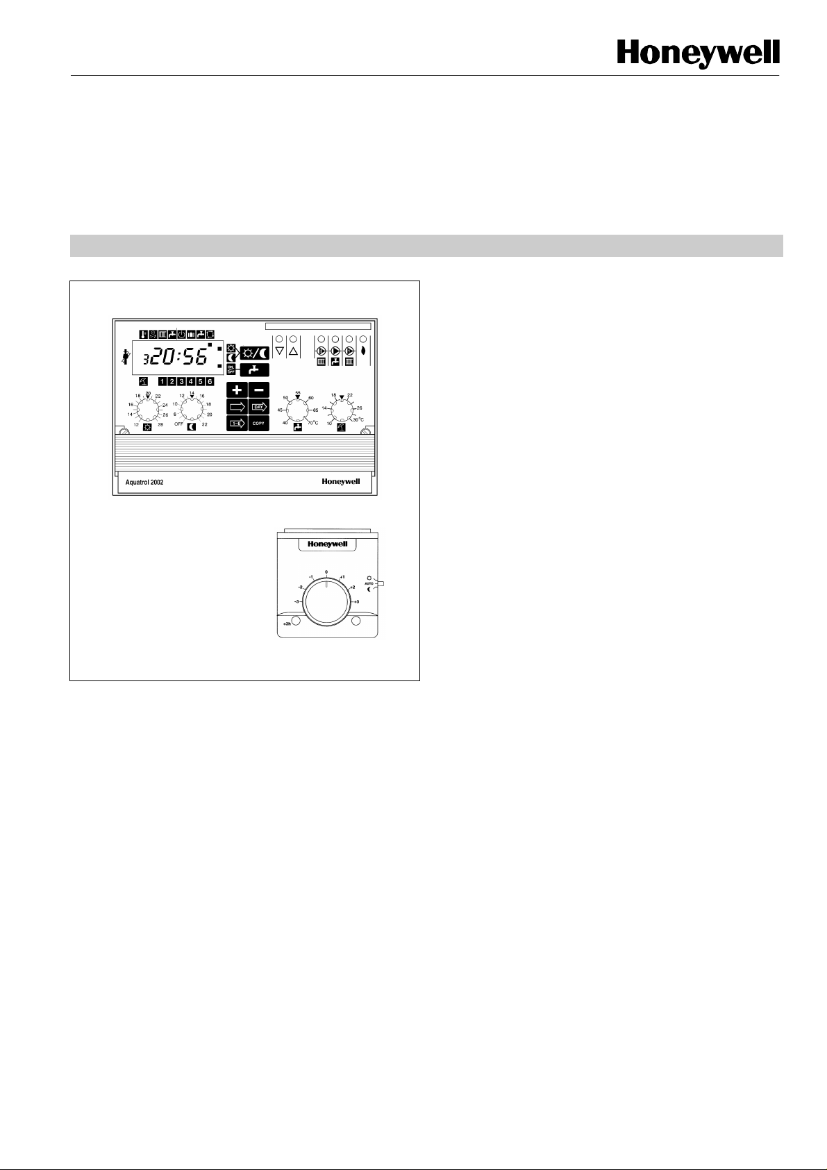
AQ2002
Room unit (optional)
APPLICATION
Aquatrol 2002 is a straightforward, versatile controller which
forms the basis of an outside compensated control system
for single or dual zone low pressure hot water heating
systems. The controller offers build-in optimizer and many
other advanced featured whilst still retaining simple user
adjustments.
It provides self adaptive heating curve, optimum start/stop
operation, outside air compensated mixed water control
using a 3-port motorized valve and pump, boiler, and
domestic hot water control using a valve and/or pump.
A wide range of compatible sensors, a remote unit, valves
and actuators complement the control system.
AQ2002
OPTIMISER/COMPENSATOR
CONTROLLER
PRODUCT SPECIFICATION SHEET
• Digital control technology with easy to understand
analogue installation adjustments
• Outside compensated control of low pressure hot
water heating system
• Fixed or self-adaptive heating curve (with optional
remote unit)
• Two independent heating curves for 1st and 2nd
heating zone
• Heating time programme offering switching between
comfort and economy operation up to 6 times per
day, independently for each day of the week
(selectable night off period is also available)
• Optimum Start/Stop (with optional space sensor) or
Heating Boost on start-up (without space sensor)
• Domestic Hot Water (DHW) time programme offering
up to 6 switching points per day independently for
each day of the week
• DHW programme can alternatively be used as the
heating programme for second heating zone
• Holiday mode with programmable 1 to 99 day holiday
period and dynamic countdown display
• Automatic, DHW only, Holiday or Standby operation
• LED’s indicate control output status
• Pump and valve exercise which helps prevent
sticking during long periods of inactivity
• Frost protection of the pipework, hot water cylinder
and the building fabric (with optional space sensor)
• Automatic summer heating mode changeover (user
adjustable)
• Automatic heating shutdown under minimal load
conditions
• Softstart to help prevent pipe expansion noise
• Service switch to assist installer on start-up and
technician during service
• Intelligent pump control with energy efficient pump
overrun
• Built-in user programme
• Optional remote unit providing space temperature
sensing, space temperature adjustment,
comfort/economy override switch and 3 hour comfort
extension button with confirmation LED
1 EN0R8527R0
Page 2
AQ2002 Optimiser/Compensator Controller
: IP40 (with base fitted and when installed
: 144 x 96 x 107 mm (with standard base)
SPECIFICATIONS
SYSTEM SELECTION CHART
Radiator or
With
On/Off Burner
Radiator
Single
Without
Pumped
Diverting
Radiator or
Radiator and
Single
Dual
On/Off Burner
On/Off Burner
With
With
Without
With
With
Pumped
Pumped
67134
5
2
Without
Without
APPLICATIONS
Supply voltage: 230 V~, +10% -15%, 50 Hz
Power
: 8 W
Consumption
Relay ratings : Pumps and boiler:
3 A, 230 V~ @ 0.6 pf - 400,000 oper.
Mixing valve:
0.25 A, 230 V~ @ 0.4 pf - 1,000,000
oper
Sensor accuracy : Water sensors: 20°C to 90°C ±2 K
Outside sensor: -20°C to +20°C ±2 K
Room sensor: 10°C to 25°C ±0.5 K
Ambient temp.
: 0 to 50°C
rating
The chart can be used to determine the
system number (1-7) corresponding to the
required application.
Systems 1, 2 and 3 are typical Radiator
applications without mixing valve.
Systems 4 and 5 are Radiator OR
Underfloor applications with mixing valve.
Systems 6 and 7 are Dual loop Radiator
AND Underfloor applications.
Loop Systems
Humidity rating: 0 to 90% rh (non-condensing)
Storage/shipping
: -30°C to +70°C
temperature
Electromagnetic
compatibility
: Emissions to EN55014-1
Immunity to EN55014-2
Protection class
to EN60529)
Dimensions
(w x h x d)
Panel cut-out
144 x 153 x 109 mm (with wiring centre)
: 138 x 92 mm
(w x h)
Weight : 600 g
AQ2002
Underfloor
Underfloor
Loop Systems
Loop Systems
Underfloor
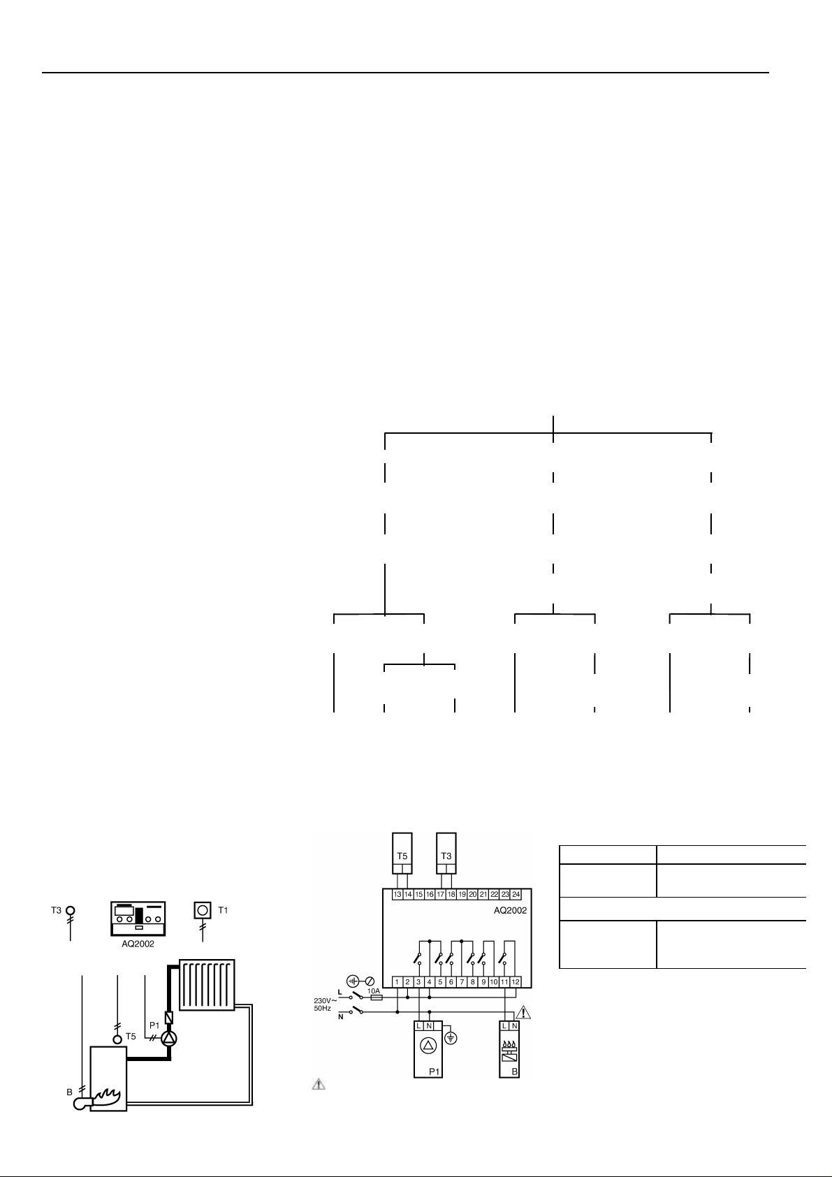
SYSTEM 1
Application
This system offers intelligent ON/OFF
burner and pump control for radiator
heating.
Control
DHW
DHW
DHW
Valve
Electrical Connections
Mixing Valve
DHW
Control
DHW
DHW
DHW
DHW
Temperature sensors
T3 Outside air T7043E
T5 Boiler
supply
Optional
T1 Remote
unit
Control
Mixing Valve
DHW
DHW
T7076D insertion or
T7043F immersion
T8102B1001 Full
function remote unit
including wall plate.
EN0R 8527 R0 2
For potential free connection, please refer
to boiler connection section
Page 3
AQ2002 Optimiser/Compensator Controller
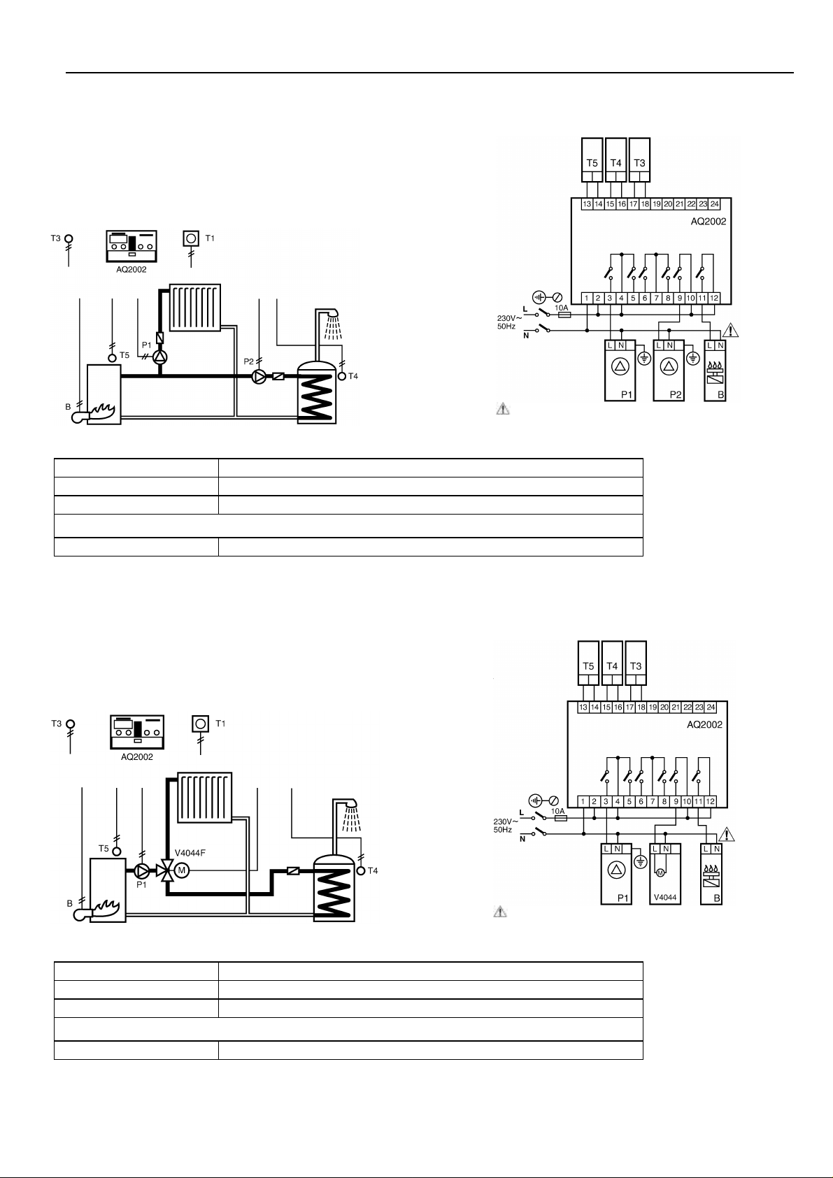
SYSTEM 2
SYSTEM 3
Application
This system offers intelligent ON/OFF burner and pump
control for radiator heating.
This system also provides a second pump to meet the
demands for domestic hot water.
Electrical Connections
For boiler potential free connection, please refer
to boiler connection section
Temperature sensors
T3 Outside air T7043E
T4 Domestic hot water T7076D insertion or T7043F immersion
T5 Boiler supply T7076D insertion or T7043F immersion
Optional
T1 Remote unit T8102B1001 Full function remote unit including wall plate.
Application
This system offers intelligent ON/OFF burner and pumps
control for radiator heating and uses a diverted valve to meet
the demands of domestic hot water
Electrical Connections
For boiler potential free connection, please refer
to boiler connection section
Temperature sensors
T3 Outside air T7043E
T4 Domestic hot water T7076D insertion or T7043F immersion
T5 Boiler supply T7076D insertion or T7043F immersion
Optional
T1 Remote unit T8102B1001 Full function remote unit including wall plate.
EN0R 8527 R03
Page 4
AQ2002 Optimiser/Compensator Controller
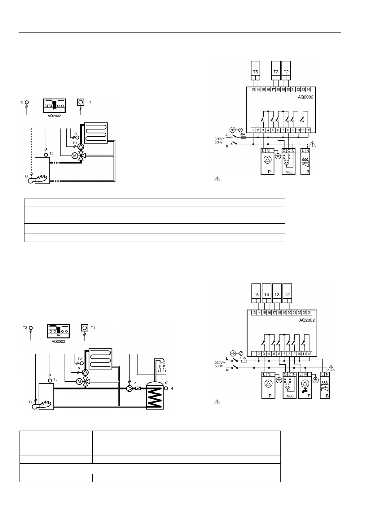
SYSTEM 4
with mixing valve control for radiator or underfloor heating.
with a mixing valve and a pump control without boiler control.
SYSTEM 5
with mixing valve control for radiator or underfloor heating.
Application
This system offers intelligent ON/OFF burner and pump control
This system can also be used for a single heating loop equipped
Electrical Connections
For boiler potential free connection, please refer
to boiler connection section
Temperature sensors
T2 Mixed water T7044C strap on or T7043F immersion
T3 Outside air T7043E
T5 Boiler supply T7076D insertion or T7043F immersion
Optional
T1 Remote unit T8102B1001 Full function remote unit including wall plate.
Application
This system offers intelligent ON/OFF burner and pump control
This system also provides a second pump to meet the demands
for domestic hot water.
Electrical Connections
For boiler potential free connection, please refer to
boiler connection section
Temperature sensors
T2 Mixed water T7044C strap on or T7043F immersion
T3 Outside air T7043E
T4 Domestic hot water T7076D insertion or T7043F immersion
T5 Boiler supply T7076D insertion or T7043F immersion
Optional
T1 Remote unit T8102B1001 Full function remote unit including wall plate.
EN0R 8527 R0 4
Page 5

AQ2002 Optimiser/Compensator Controller
SYSTEM 6
SYSTEM 7
Application
This dual loop system offers intelligent ON/OFF burner and
pump control for radiator loop and mixing valve control for
underfloor loop.
Electrical Connections
For boiler potential free connection, please refer to
boiler connection section
Temperature sensors
T2 Mixed water T7044C strap on or T7043F immersion
T3 Outside air T7043E
T5 Boiler supply T7076D insertion or T7043F immersion
Optional
T1 Remote unit T8102B1001 Full function remote unit including wall plate.
Application
This dual loop system offers intelligent ON/OFF burner and pump
control for radiator loop and mixing valve control for underfloor
loop.
This system also provides a third pump to meet the demands for
domestic hot water.
Electrical Connections
For boiler potential free connection, please refer to boiler
connection section
Temperature sensors
T2 Mixed water T7044C strap on or T7043F immersion
T3 Outside air T7043E
T4 Domestic hot water T7076D insertion or T7043F immersion
T5 Boiler supply T7076D insertion or T7043F immersion
Optional
T1 Remote unit T8102B1001 Full function remote unit including wall plate.
EN0R 8527 R05
Page 6

AQ2002 Optimiser/Compensator Controller
within the range 40 to 70°C.
within the range 10 to 30°C. When the
CONTROLLER FEATURES
within the range 4 to 40 using this
Comfort Setpoint
LCD Display
User
Adjustments
Installer
Adjustments
The desired space Comfort temperature
can be set within the range 12 to 28°C.
Override
Buttons
System Selector Switches
Programming/Operating
Buttons
Cycle Rate Adjustment
The cycle rate adjustment allows the cycle
rate as recommended by the boiler
manufacturer to be set directly on the
controller.
Output Status
Indicators
User
Adjustments
Installer
Adjustments
Economy Setpoint
The desired Economy temperature can
be set within the range 8 to 22°C.
Economy OFF can be selected by
turning the knob to the OFF position.
Domestic Hot Water Setpoint
The DHWS temperature can be set
Automatic Summer/Winter Changeover
Temperature Setpoint
Boiler/Mixed Flow Temperature High Limit
In systems with no mixing valve (no T2
sensor) the maximum value of the boiler
supply water temperature (T5) can be
adjusted by this setting.
In systems with T2 sensor and mixing valve
the maximum mixed water temperature will
be adjusted by this setting. In this case, the
maximum boiler supply temperature is fixed
at 90°C.
Heating Curve Ratio Adjustment
Two Heating Curve Ratio Adjustments
are proposed, one for each loop.
If a fixed value of the heating curve ratio
is required then this value can be set
potentiometer.
To determine the heating curve required
refer to the graph displayed below.
Ratio
The automatic Summer/Winter
changeover temperature can be set
average daily outdoor temperature is
above the automatic Summer/Winter
setpoint the heating will be turned off.
EN0R 8527 R0 6
Outside Air Temperature oC (T3)
Page 7

AQ2002 Optimiser/Compensator Controller
USER OPERATION
will operate at the economy space setpoint and the hot water
will be restarted in automatic mode and controlled according
Built-in Heating and DHW Program
Two different built programs are available, the first one is
designed for the first heating loop, and the second one can be
assigned either for second heating loop or DHW system
(depending of switch S2 position).
Heating program offer switching between comfort and
economy operation up to 6 times per day, independent for
each day of the week.
DHW program offer switching between ON and OFF operation
up to 6 times per day, independent for each day of the week.
Holiday Program
When the holiday mode of operation is selected, the heating
control will be inactive (except for frost protection) until the set
number of days has elapsed. When the heating and hot water
to the programmed data.
The return to automatic occurs at 0:00 the day the heating is
required.
System Temperature Enquiry
By switching to the enquiry mode all system temperature and
the adapted heating curve value (or the value of the heating
curve compensation slope knob if fixed compensation is
selected) can be displayed on the LCD.
Only the current temperature and parameter value will be
displayed.
This facility is not available during the initial start-up
procedure
REMOTE UNIT
Electrical connection
Room
Unit
CONTROLLER OPERATION
Outside temperature compensation
The Aquatrol 2002 is an outside temperature controller
compensated designed for most of heating systems
composed by boiler, circuit with or without mixing valve, and
domestic hot water.
Fixed or Self Adaptive Heating Curve
Room temperature compensation is available (in CH zone 1
only) when a remote room unit is connected. The fixed or
self adaptive heating curve function is selected by switch
S7.
Optimum Start/Stop
If a remote room unit is present, the controller automatically
calculates the ideal times for starting the setback and
heating-up phases defined by the heating program, in order
to save energy without sacrificing comfort. Without a room
sensor, optimum start/stop is not possible and a heating
boost is implemented in advance of an upward heating
setpoint change.
Note: optimum start and stop are applicable only to CH
zone 1 since only that zone can have a remote room
unit.
The AQ2002 controller can be completed by a remote unit
(optional) , its allow the user to adjust rapidly on controller
setpoints without going to the boiler room.
The remote unit incorporates a space temperature sensor, a
remote setpoint adjustment knob with adjustable range stops,
a 3 hour extension push button with LED indication, and a
manual switch to override the operating mode. The day or
night flag will flash on controller when the mode is overridden.
When used as a space temperature sensor, the same
mounting directions for the space sensor temperature applies.
The unit is a 2 wire connection polarized.
Comfort/Economy
Override Switch
Comfort
Extension
Button Remote Space
Temperature
Adjustment
Comfort Extension Indicator (LED)
Frost Protection of the Pipework
Frost protection of the heating system applies at all times
and in all operating modes of the controller.
Automatic Shutdown
During periods when there is no requirement for heat, the
controller will shut down the system including turning off the
heating pumps.
Automatic Summer/Winter Changeover
When the daily average outdoor temperature is high, then
the heating is turned off (pumps off, boiler off, valve closed).
The summer/winter changeover temperature is adjustable
via a potentiometer.
Pump and Valve Exercise
In order to prevent sticking or jamming of components
during long periods of inactivity, for example in the summer,
then a pump/valve exercise will take place once a week at
12:00 on Fridays.
DHWS Operation
When a DHW temperature (T4) sensor is connected, the
DHW temperature is controlled to a user-adjustable set
point.
There are two variants for combined DHWS; DHWS
Priority/Shifting or Parallel priority operation. In all two
EN0R 8527 R07
Page 8

AQ2002 Optimiser/Compensator Controller
DHWS Priority/Shifting Priority
In heating circuits with no mixing valve (and no mixed flow
temperature sensor), the DHWS has priority over the
heating.
In heating circuits with mixing valve, operation is as follows:
While the boiler temperature is less than a differential of
10K above the DHW setpoint, the mixing valve will be
closed giving DHW priority. However if there is surplus heat
available and the boiler temperature is more than 20K (the
differential plus a proportional-band of 10K) above the DHW
setpoint then the mixed heating loop will control at its
calculated setpoint, servicing the heating in parallel with the
DHW. If the boiler temperature is between these two values
then the mixed water setpoint is reduced.
Note: In dual loop systems, the CH zone 2 pump will be
switched off during a DHW service.
DHWS Parallel
In heating circuits with mixing valve when parallel operation
has been selected central heating will continue to operate
normally during a DHW service.
Note: In some systems selection of parallel operation may
result in extended DHW recovery times or in extreme
cases DHW never being satisfied
Note: Any heating loop supplied directly from the boiler will
be shut down during DHW demand period no matter
what is the position of S4 switch.
• If a DHWS sensor (T4) is present then combined or
separate temperature control of the DHWS will be
available. If no DHWS sensor (T4) is present only time
control is available on the DHWS output.
Automatic system detection takes place during the first minute
after powering the controller.
System Selection Switches
SwitchDescription Position A Position B
S1 Boiler low limit 20°C 45°C
S2 2nd time programme DHW CH zone 2
S3 DHWS program programmed continuous
S4 DHWS operation
S5 DHW actuator device pump valve
S6 Type of heating radiator underfloor
S7 Adaptive heat curve 1 yes no
Priority/ Shifting
operation
parallel
INSTALLER START UP SEQUENCE
To initiate the installer start up sequence the service switch
must be set to the "1" position with the power to the
controller switched OFF.
When power is now switched ON the above sequence will
start. The sequence can be stopped at any time by moving
the service switch to the "0" position.
SYSTEM SELECTION
System selection is achieved in two manners:
• Automatic System Selection
• System Selector Switches
Automatic System Selection
The AQ2002 is able to recognize which temperature sensor
is connected.
• If a mixed flow water sensor (T2) is connected, the
controller assumes that a mixing valve is present.
• If a Remote Unit (T1) is present the controller activates
the space temperature compensation, the optimum
Start/Stop and the self-adaptive heating curve (if switch
S7 on position A).
S8 Heating zones one/single loop two/dual loop
Shading indicates position as supplied from the factory
S1 Boiler Minimum Temperature
Allows to set the minimum boiler temperature:
- Position A: 20°C, no boiler temperature low limit
- Position B: 45°C
NOTE: Low limit will apply also to the 2nd CH heating zone flow
temperature
S2 Second time program
See table
S3 DHW Time Programme
Allows to select the timed or continuous operation of DHW.
If the S2 is in position B and S3 in position A, DHW will operate
according to both heating zone programmes.
S4 DHW Operation
DHW demand can be served in one of the following modes:
- Position A: Priority or Shifting Priority.
Please refer to “DHWS Operation” section
- Position B: parallel.
Please refer to “DHWS Operation” section
S5 DHW Actuator Device
S5 allows you to configure AQ2002 for systems where diverting
valve is used to switch the boiler output to CH or DHW
installation. Use of diverting valve is only allowed in systems
without mixing valve.
- Position A: on DHW demand the DHW pump will be switched
on.
- Position B: on DHW demand the diverting valve will be driven
to DHW position and CH pump will continue to run forcing the
flow through the hot water heat exchanger.
EN0R 8527 R0 8
S6 Type of heating
Page 9

AQ2002 Optimiser/Compensator Controller
S6 Type of heating
See table
S7 Adaptive Heating Curve 1
To benefit from this feature a remote unit must be installed.
During normal heating periods estimates are made for the
heating curve ratio 1. Each day controller compares its
performance to meet the criteria of achieving the day space
temperature.
A new value for the heating curve ratio 1 is stored daily in the
controller’s memory such that within 4 to 6 days, from the
initial start-up it will have changed the initial heating curve to
one that more closely matches the building’s thermal
characteristics.
During this learning phase the room compensation will assist
in providing comfortable space temperature conditions.
S8 Heating zones
See table
SYSTEM ON INDICATION
Each output is monitored by LED.
Fault
Description Controller Action
Code
F1 Dual loop ratio
setting fault
CH1 ratio has priority: set ratio 1 under
ratio 2 following installation requirements
F2 T2 sensor fault Acts as system without mixing valve.
F3 T3 sensor fault Heating on at or above frost protection
values.
F4 Not used
F5 T4 sensor fault DHW output held off.
F6 T5 sensor fault If frost protection active: Boiler cycles at
20%.
If no frost protection: Boiler off
F7 T1 remote unit.
Acts as system without remote unit.
fault
F8 Internal fault Boiler cycles at 20%, valve opens.
F9 Remote unit
Acts as system without remote unit.
fault
DIMENSIONS
Controller Dimension in mm
When the LED is illuminated it indicates that:
The mixing valve actuator is being driven closed,
reducing Heating.
The mixing valve actuator is being driven open,
increasing Heating.
Heating pump 2 is ON.
The DHW is ON.
Heating pump 1 is ON.
Boiler output is ON.
FAULT CODES
Should a fault occur in the system a fault code will be
displayed on the LCD. The table below gives details of the
codes and the action taken by the controller.
Information:
The above table also indicates the priority of the fault. The
lower the code the higher the priority.
An open circuit is used to automatically select the control
system configuration for DHW, mixing systems and for the
Remote Unit. A fault is not displayed if an open circuit is
detected on the T2, T4 & T5 sensors or the Remote Unit
terminals within the first minute after switching power on.
Surface Mounting
The Aquatrol 2000 controller can be surface mounted in either
a control panel or directly on the wall.
Panel Mounting
The controller can be panel mounted in a control panel door
and features integral panel mounting clips for ease of
installation.
Panel cut-out (w x h) : 138 x 92 mm
EN0R 8527 R09
Page 10

AQ2002 Optimiser/Compensator Controller
INSTALLATION
wiring.
Important
1. The installer must be a trained engineer
2. Disconnect the power supply before beginning
installation
The recommended wiring is as follow:
From Controller to … Maximum Length Type of wire
Temperature sensor 100m
Remote unit 50m
Boiler/Burner 100m
Motorized valve 100m
Pumps 100m
Other devices 100m
To meet the
requirements of
local standards
Boiler connection
ON/OFF boilers can be connected and controlled by two
different manners:
• ON/OFF boiler supplied and controlled by line voltage
Tamper-Proofing
The controller can be made tamperproof, if required, by
inserting a wire link through the hole in the front clear cover
and the front housing at the top center of the front panel
and twisting or crimping to fix the front panel permanently
shut, thus preventing unauthorized adjustment.
Wall Mounting using Wiring Centre (Optional)
For wall mounting the optional Wiring Center K42007745005 can be used for protection and termination of electrical
conduits, MICC cable or Pirelli FP200 cables with suitable
adapters.
CONNECTIONS
Controller Connection
The controller operates from a 230V 50Hz power supply.
Cables providing power to the controller should be sized to
match the individual installation requirements for distance
and power consumption. The AQ2002 controller requires an
effective earth directly from the building’s consumer unit in
order to meet the same earthing requirements for the
temperature sensors.
Each terminal within the controller is capable of accepting
either two cables with a maximum cross sectional area of
1.5mm2 or one cable with a maximum cross sectional area
of 2.5mm2.
Please refer to your system for the correct input/output
• ON/OFF boiler supplied by the line voltage and control
by a free voltage contact
Boiler relay ratings
Boiler: 3 A, 230 V~ @ 0.6 pf
EN0R 8527 R0 10
Page 11

CONTROLLER ORDERING SPECIFICATION
Ordering specification: W6060C1141 Belgium and French version
Specifications
water pipe providing a temperature input
water pipe, or inserted in a well, and
W6060C1158 English version
OTHER SYSTEM COMPONENTS (to be ordered separately)
Outside Temperature Sensor T7043E
Application
The Outside Temperature Sensor consists
of a thermistor element housed in a tough
plastic case. It is mounted outside the
building providing a temperature input
signal to the controller.
Ordering Specification: T7043E1008
Flow Temperature Sensor T7044C
Sensing range : -30 to +40°C
Sensor : NTS type 10 kΩ @ 25°C
Enclosure : Plastic with integral
Pg11 fitting
Dimensions : 66 ∅ x 35 mm
AQ2002 Optimiser/Compensator Controller
Application
The T7044C Strap-on Flow Water
Temperature Sensor consists of a
thermistor sensing element housed in a
tough plastic case. It is strapped to the flow
signal to the controller.
Ordering Specification: T7044C1002
Flow Temperature Sensor T7043F
Application
The T7043F Immersion Flow Water
Temperature Sensor consists of a
thermistor sensing element housed in an
immersion pocket. It should be mounted on
a bend on the flow water pipe providing a
temperature input signal to the controller
Ordering Specification: T7043F1006
Insertion Temperature Sensor T7076D
Application
The T7076D tape-on or insertion sensor
consists of a thermistor sensing element
encapsulated in plastic. It is designed for
use in outside temperature compensated
heating systems. It can be taped on to a hot
provides a temperature input signal to the
controller. For tape-on installation, a
polyester and an aluminium tape are
supplied.
Ordering Specification: T7076D1001
Specifications
Sensing range : 0 to 115°C
Sensor : NTS type 10 kΩ @ 25°C
Enclosure : Plastic with integral
Pg11 fitting
Dimensions : 72 ∅ x 48 mm
Specifications
Sensing range : 0 to 115°C
Sensor : NTS type 10 kΩ @ 25°C
Enclosure : Plastic with integral
Pg11 fitting
Dimensions : 72 ∅ x 45 mm
Well : ½" BSPT x 100 mm
Specifications
Sensing range : 0 to 110°C
Maximum
Ambient temp. : 115°C
Wire dimensions : 1.3mm ∅ x 1.5m long.
Sensor : NTS type 10 kΩ @ 25°C
Wire rating : -30 to +115°C
Dimensions : 7 Ø x 25 mm
Temperature Sensor Characteristics
EN0R 8527 R011
Page 12

AQ2000 OPTIMISER/COMPENSATOR CONTROLLER
Specifications
RELATED LITERATURE
Remote Unit T8102B
Application
The Remote Unit provides a space
temperature sensor input signal to the
AQ2000 for space temperature
compensation and to enable the
optimization and adaptive ratio to function.
Remote adjustment of the setpoint is also
possible and an override switch gives the
possibility of selecting permanent comfort
or economy settings. A "party" button
allows a three hour comfort extension to be
selected.
Ordering Specification:
T8102B1001 with English literature
T8102B1050 with French literature
T8102B1068 with Italian literature
Sensor : NTS type 10 kΩ @ 25°C
Housing : White plastic
Weight : 70 g
Dimensions : 70 x 75 x 31 mm (w x h x
d)
Setpoint : ± 3 K
adjustment
Wiring Centre K42007745-005
Application
The Wiring Centre is an essential
component when mounting the controller
on a wall. It provides a number of conduit
entries through the bottom, back and
sides. In addition, it provides extra
terminals to link multiple incoming cables
such as line, neutral and earth.
Ordering Specification:
K42007745-005
Specifications
Housing : White Plastic
Cable entries : 17 x 19 mm conduit entries
Dimensions : 70 x 75 x 31 mm (w x h x
d)
(9 bottom, 3 right side, 1 left
side, 4 back)
AQ2002 Installation Guide 42010344-001 in English
42010344-002 in French
AQ2002 User Guide 42010345-001 in English
42010345-002 in French
Honeywell Control Systems Limited http://europe.hbc.honeywell.com
Newhouse Industrial Estate
Motherwell ML1 5SB
United Kingdom
EN0R 8527 R0
 Loading...