

Page 1

Hydronic Zoning Thermostat
AQ1000TN2
OWNER’S GUIDE
Place Bar Code Here
Page 2

Need Help?
For assistance with this product please visit http://yourhome.honeywell.com
or call Honeywell Customer Care toll-free at 1-800-468-1502.
Read and save these instructions.
® U.S. Registered Trademark. Patents pending.
© 9-06 Honeywell International Inc. All rights reserved.
69-2005EF
Page 3

Table of contents
User’s section
About your new thermostat....................................................................................1
Screen display .......................................................................................................2
Power-up / modes of operation..............................................................................3
User’s configuration menu.....................................................................................4
Temperature display and setting............................................................................6
Installer’s section
Installation..............................................................................................................7
Configuration switches...........................................................................................8
Installer’s configuration menu................................................................................9
Appendix
Technical specifications.......................................................................................12
2-year limited warranty ........................................................................................13
69-2005EF
Page 4

About your new thermostat
Honeywell’s AQ1000TN2 hydronic zoning thermostat can be used to control the ambient air
temperature or floor temperature. You can
choose among the following temperature control modes (see page 8):
A mode:
F mode:
AF mode:
• controls and displays the
ambient air temperature
• controls and displays the floor
temperature using an external
temperature sensor
• controls and displays the
ambient air temperature
• maintains the floor temperature
within desired limits using an
external temperature sensor
1 69-2005EF
Screen
Temperature
adjustment
buttons
Backlight
button
Page 5

Screen display
The arrow appears when
the setpoint is displayed
Temperature
control mode
Indoor temperature
Outdoor temperature
1
Heating is On
Freeze Protection mode
(see next page)
1
The outdoor temperature will be displayed only if the data is available.
2
This icon appears to indicate that the thermostat settings cannot be modified as the hydronic
Keypad lock
Comfort / Unoccupied mode
(see next page)
2
zoning controller has locked the keypad. The backlight button and the buttons can still be
used to activate the backlight and to display the setpoint.
2 69-2005EF
Page 6

Power-up / modes of operation
The thermostat is powered through the wires connecting it to the AQ2000 Series
hydronic zoning controller. Therefore, the thermostat turns on when the controller is
powered. The thermostat can be placed in one of the 3 following modes of operation:
Comfort Mode
The thermostat is normally in the Comfort mode. In this mode, the
temperature is set using the buttons.
Unoccupied Mode
When the Unoccupied mode is activated by the hydronic zoning controller,
the temperature setpoint is lowered by the temperature setback value.
This value is set in the User’s configuration menu (see page 5).
Freeze Protection Mode
When the Freeze Protection mode is activated by the hydronic zoning
controller, the thermostat is placed at the Freeze Protection temperature.
This value is set in the Installer’s configuration menu (see page 10).
3 69-2005EF
Page 7
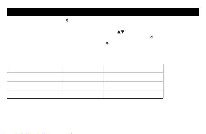
User’s Configuration Menu
1. Press the backlight button for 3 seconds to access the configuration menu.
The first parameter is displayed.
2. To modify a parameter, press either of the buttons.
3. To display the next parameter, briefly press the backlight button.
4. To exit the menu, press the backlight button for 3 seconds.
The parameters appear in the order shown in the following table.
Parameter Default setting Options
Display mode Automatic Automatic, °F, °C
Temperature setback 7 °F (4 °C) 0 to 16 °F (0 to 9 °C)
Backlight Temporary Temporary / Permanent
4 69-2005EF
Page 8

Display Format
Use this parameter to choose the temperature display mode. When
the automatic mode is selected, the thermostat displays the
temperature format set on the hydronic zoning controller. If °F or °C is
selected, the thermostat displays the temperature in the selected
format respectively.
Temperature Setback
When the Unoccupied mode is activated by the hydronic zoning
controller (certain controller models only), the temperature setpoint is
lowered (set back). Use this parameter to specify the amount of
temperature setback.
Backlight
Use this parameter to choose between temporary and permanent
backlight. When temporary backlight is selected, the screen is lit for
12 seconds every time any button is pressed.
5 69-2005EF
Page 9
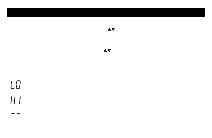
Temperature Display and Setting
The thermostat generally displays the actual (measured) temperature. To display the
setpoint temperature, press one of the buttons once. The setpoint will be
displayed for the next 5 seconds. An arrow appears at the left of the setpoint
temperature display.
To change the setpoint, press one of the buttons until the desired temperature is
displayed. To scroll faster, press and hold the button.
Error Messages
The measured temperature is below the thermostat’s display range.
The measured temperature is above the thermostat’s display range.
Verify the thermostat and external (floor) sensor connections.
6 69-2005EF
Page 10

Installation
1. Remove the faceplate from the base by unscrewing the screw underneath the ther-
mostat and tilting the bottom of the faceplate up. Note that the screw remains captive on the base.
2. Insert the wires through the center hole of the base and secure the base to the wall
or onto an electrical box.
3. Connect the wires to the terminals (no polarity to observe).
Terminal Description
1TH
2TH
3 SENSOR External sensor connections for floor temperature
4SENSOR
4. Set the configuration switches (see next page).
5. Re-attach the faceplate to the base and secure with the captive screw.
NOTE: Keep the thermostat's air vents clean and unobstructed at all times.
AQ2000 Series hydronic zoning controller connections
measurement (required only if the thermostat is set to F
or AF mode; see pages 1 and 8)
7 69-2005EF
Page 11

Configuration switches
The configuration (DIP) switches are located behind the
thermostat faceplate.
NOTE : DIP switch 1 is not used.
Installer Configuration Menu (switch 2)
Use DIP switch 2 to set the thermostat in either Installer or
User mode.
Temperature Control Mode (switches 3 & 4)
Use DIP switches 3 and 4 to select the temperature control
mode (A, F or AF).
NOTE : F or AF mode should be used only when an external
(floor) sensor is connected to the thermostat (see page 7).
8 69-2005EF
Page 12

Installer’s Configuration Menu
The parameters in the installer’s configuration menu must be modified by qualified
personnel only. Incorrect settings can result in property damages.
1. Remove the thermostat from its base.
2. Place switch 2 on the back of the thermostat in the up position (Installer mode).
3. Return the thermostat to its base. The first parameter is displayed.
4. To modify a parameter, press either of the buttons.
5. To view the next parameter, briefly press the backlight button.
6. To exit the menu, place switch 2 back to its initial position.
The parameters appear in the order shown in the following table.
Parameter Default setting Range
Minimum setpoint temperature 41 °F (5 °C) 41 °F (5 °C) to 100 °F (38 °C)
Maximum setpoint temperature 100 °F (38 °C) 41 °F (5 °C) to 100 °F (38 °C)
Freeze Protection temperature 41 °F (5 °C) 41 °F (5 °C) to 100 °F (38 °C)*
Minimum floor limit 41 °F (5 °C) 41 °F (5 °C) to 100 °F (38 °C)
Maximum floor limit 100 °F (38 °C) 41 °F (5 °C) to 100 °F (38 °C)
* The Freeze Protection temperature range is set by the minimum and maximum setpoint temperatures.
For example, if you change the minimum setpoint temperature to 50 °F (10 °C), you cannot then set the
Freeze Protection temperature lower than 50 °F (10 °C).
9 69-2005EF
Page 13

Minimum Setpoint Temperature
This parameter is the minimum temperature at which the thermostat
can be set.
Maximum Setpoint Temperature
This parameter is the maximum temperature at which the thermostat
can be set.
Freeze Protection Temperature
This parameter is used to prevent frozen pipes inside the room where
the thermostat is located. When the Freeze Protection mode is activated by the hydronic zoning controller, the thermostat is placed at
the Freeze Protection temperature.
10 69-2005EF
Page 14

Minimum Floor Limit Temperature
This parameter is used only if the thermostat has been configured for
AF temperature control. If the floor temperature is below that limit, the
pump or valve will be activated regardless of the ambient temperature.
Maximum Floor Limit Temperature
This parameter is used only if the thermostat has been configured for
AF temperature control. If the floor temperature is above that limit,
the pump or valve will be deactivated regardless of the ambient temperature.
11 69-2005EF
Page 15

Technical Specifications
Power supply: powered by the boiler controller
Default setpoint range: 40 °F to 100 °F (5 °C to 38 °C)
Default floor limit (AF model): 40 °F to 100 °F (5 °C to 38 °C)
Setpoint interval: ± 1.0 °F (0.5 °C)
Indoor temperature display range: 32 °F to 158 °F (0 °C to 70 °C)
Outdoor temperature display range: -58 °F to 212 °F (-50 °C to 100 °C)
Display resolution: ± 1.0 °F (0.5 °C)
Storage: -20 °F to 130 °F (-30 °C to 55 °C)
Controller type: Proportional Integral (PI)
Memory type: All settings are stored in non-volatile memory and are therefore safe
during a power outage
12 69-2005EF
Page 16

2-year limited warranty
Honeywell warrants this product, excluding battery, to be free from defects in the workmanship
or materials, under normal use and service, for a period of two (2) years from the date of
purchase by the consumer. If at any time during the warranty period the product is determined
to be defective or malfunctions, Honeywell shall repair or replace it (at Honeywell’s option).
If the product is defective,
(i) return it, with a bill of sale or other dated proof of purchase, to the place from which you
purchased it; or
(ii) call Honeywell Customer Care at 1-800-468-1502. Customer Care will make the
determination whether the product should be returned to the following address: Honeywell
Return Goods, Dock 4 MN10-3860, 1885 Douglas Dr. N., Golden Valley, MN 55422, or
whether a replacement product can be sent to you.
This warranty does not cover removal or reinstallation costs. This warranty shall not apply if it is
shown by Honeywell that the defect or malfunction was caused by damage which occurred
while the product was in the possession of a consumer.
Honeywell’s sole responsibility shall be to repair or replace the product within the terms stated
above. HONEYWELL SHALL NOT BE LIABLE FOR ANY LOSS OR DAMAGE OF ANY KIND,
13 69-2005EF
Page 17

INCLUDING ANY INCIDENTAL OR CONSEQUENTIAL DAMAGES RESULTING, DIRECTLY
OR INDIRECTLY, FROM ANY BREACH OF ANY WARRANTY, EXPRESS OR IMPLIED, OR
ANY OTHER FAILURE OF THIS PRODUCT. Some states do not allow the exclusion or
limitation of incidental or consequential damages, so this limitation may not apply to you.
THIS WARRANTY IS THE ONLY EXPRESS WARRANTY HONEYWELL MAKES ON THIS
PRODUCT. THE DURATION OF ANY IMPLIED WARRANTIES, INCLUDING THE
WARRANTIES OF MERCHANTABILITY AND FITNESS FOR A PARTICULAR PURPOSE, IS
HEREBY LIMITED TO THE TWO-YEAR DURATION OF THIS WARRANTY.
Some states do not allow limitations on how long an implied warranty lasts, so the above
limitation may not apply to you. This warranty gives you specific legal rights, and you may have
other rights which vary from state to state.
If you have any questions concerning this warranty, please write Honeywell Customer
Relations, 1985 Douglas Dr, Golden Valley, MN 55422 or call 1-800-468-1502. In Canada, write
Retail Products
ON15-02H, Honeywell Limited/Honeywell Limitée, 35 Dynamic Drive, Scarborough, Ontario
M1V4Z9.
14 69-2005EF
Page 18

Automation and Control Solutions
Honeywell International Inc. Honeywell Limited-Honeywell Limitée
1985 Douglas Drive North 35 Dynamic Drive
Golden Valley, MN 55422 Toronto, Ontario M1V 4Z9
yourhome.honeywell.com
® U.S. Registered Trademark
© 2006 Honeywell International Inc.
69-2005EF Rev. 9-06
Page 19

Thermostat de zonage hydronique
AQ1000TN2
GUIDE DU PROPRIÉTAIRE
Place Bar Code Here
Page 20

Besoin d’aide?
Pour obtenir de l’aide sur ce produit, veuillez consulter le http://yourhome.honeywell.com
ou joindre le service à la clientèle en composant sans frais le 1 800 468-1502
Veuillez lire le mode d’emploi et le conserver en lieu sûr.
® Marque de commerce enregistrée aux États-Unis. Brevets en instance.
© 10-06 Honeywell International inc. Tous droits réservés.
69-2005EF
Page 21

Table des matières
Section de l’utilisateur
À propos du thermostat .........................................................................................1
Affichage................................................................................................................2
Mise sous tension / modes de fonctionnement......................................................3
Menu de configuration de l’utilisateur ....................................................................4
Affichage et réglage de la température..................................................................6
Section de l’installateur
Installation..............................................................................................................7
Commutateurs de configuration.............................................................................8
Menu de configuration de l’installateur ..................................................................9
Annexe
Fiche technique ...................................................................................................12
Garantie limitée de 2 ans.....................................................................................13
69-2005EF
Page 22

À propos du thermostat
Le thermostat de zonage hydronique
AQ1000TN2 de Honeywell permettent de
réguler la température ambiante ou la température du plancher. Vous pouvez choisir l’un
des modes de régulation de la température
suivants (voir la page 8) :
Écran
Mode A : • régulation de la température
ambiante
Mode F : • régulation de la température du
plancher au moyen d’une sonde de
température externe
Mode AF :• régulation de la température
ambiante
• maintien la température du plancher
dans les limites désirées au moyen
d’une sonde de température externe
Boutons
d’ajustement
de la
température
Bouton de
rétroéclairage
1 69-2005EF
Page 23

Affichage
La flèche apparaît lorsque
la température de consigne
est affichée
Mode de régulation
de la température
Température intérieure
Température extérieure
1
Chauffage en cours
Mode Hors-gel
(voir la page suivante)
1
La température extérieure sera affichée uniquement si les données sont disponibles.
2
Cette icône apparaît pour indiquer que les réglages du thermostat ne peuvent être modifiés,
Clavier verrouillé
Mode Confort / Inoccupé
(voir la page suivante)
2
puisque le régulateur hydronique de zonage a verrouillé le clavier. Le bouton de rétroéclairage
et les boutons permettent cependant d’activer le rétroéclairage et d’afficher la
température de consigne.
2 69-2005EF
Page 24

Mise sous tension / modes de fonctionnement
Le thermostat est alimenté au moyen des fils qui le relient au régulateur hydronique de
zonage Série AQ2000. Le thermostat est donc mis sous tension en même temps que le
régulateur. On peut placer le thermostat dans l’un des modes de fonctionnement suivants :
Mode Confort
Le thermostat est normalement en mode Confort. Dans ce mode, la température de consigne est réglée au moyen des boutons .
Mode Inoccupé
Lorsque le mode Inoccupé est activé à partir du régulateur, la température
de consigne est abaissée. La marge d’abaissement est modifiable à partir
du menu de configuration de l’utilisateur (voir la page 5).
Mode Hors-gel
Lorsque le mode Hors-gel est activé à partir du régulateur, le thermostat
est placé à la température Hors-gel. Cette valeur
du menu de configuration de l’installateur (voir la page 10).
3 69-2005EF
est modifiable
à partir
Page 25

Menu de configuration de l’utilisateur
1. Appuyer sur le bouton de rétroéclairage pendant 3 secondes pour accéder
au menu de configuration. Le premier paramètre apparaît.
2. Pour modifier un paramètre, appuyer sur l’un des boutons .
3. Pour afficher un autre paramètre, appuyer brièvement sur le bouton de
rétroéclairage .
4. Pour sortir du menu de configuration, appuyer sur le bouton de rétroéclairage
pendant 3 secondes.
Les paramètres apparaissent dans l’ordre indiqué dans le tableau suivant.
Paramètre Valeur par défaut Options
Mode d’affichage Automatique Automatique, °F, °C
Marge d’abaissement de la température 4 °C (7 °F) 0 °C à 9 °C (0 °F à 16 °F)
Rétroéclairage Temporaire Temporaire / Permanent
4 69-2005EF
Page 26

Format d’affichage
Ce paramètre permet de choisir le format d’affichage de la température.
Si vous choisissez le mode automatique (Au), le thermostat affichera la
température dans le format utilisé par le régulateur hydronique de
zonage. Si vous choisissez le mode °F ou °C, le thermostat affichera
respectivement la température en °F ou °C.
Abaissement de la température
Lorsque le mode Inoccupé est activé à partir du régulateur hydronique de
zonage (certains modèles de régulateurs seulement), la température de
consigne est abaissée. Ce paramètre permet de déterminer la marge
d’abaissement de la température.
Rétroéclairage
Ce paramètre permet de choisir entre le rétroéclairage temporaire et le
rétroéclairage permanent. Avec le rétroéclairage temporaire, l’écran
s’illumine pendant 12 secondes chaque fois que vous appuyez sur un
bouton.
5 69-2005EF
Page 27

Affichage et réglage de la température
Le thermostat affiche généralement la température réelle (mesurée). Pour afficher la
température de consigne, appuyer une fois sur l’un des boutons . La température
de consigne sera affichée pendant les 5 secondes suivantes. Une flèche apparaît à
gauche de la température de consigne affichée.
Pour changer la température de consigne, appuyer sur un des boutons jusqu’à
ce que la température désirée soit affichée. Pour faire défiler la température de consigne plus rapidement, maintenir le bouton enfoncé.
Messages d’erreur
La température mesurée est inférieure à la plage d’affichage.
La température mesurée est supérieure à la plage d’affichage.
Vérifier les connexions du thermostat et de la sonde externe (du plancher).
6 69-2005EF
Page 28

Installation
1. Retirer la façade du socle en desserrant la vis située sous le thermostat et en tirant
sur la partie inférieure. Noter que la vis reste captive sur le socle.
2. Insérer les fils à travers l’ouverture du centre du socle et fixer le socle sur le mur ou
sur une boîte électrique.
3. Raccorder les fils aux bornes (aucune polarité).
Borne Description
1TH
2TH
3 SENSOR Connexion de la sonde externe pour mesurer la tempéra-
4SENSOR
4. Placer les commutateurs de configuration, s’il y a lieu (voir la page suivante).
5. Remettre la façade sur le socle et serrer la vis.
NOTA : Garder les ouvertures d’aération du thermostat propres et dégagées en tout temps.
Connexion du régulateur hydronique de zonage Série
AQ2000
ture du plancher (requise uniquement si le thermostat est
placé en mode F ou AF; voir les pages 1 et 8)
7 69-2005EF
Page 29

Commutateurs de configuration
Les commutateurs de configuration (DIP switch) sont situés
au dos de la façade du thermostat.
NOTA : Le commutateur 1 n’est pas utilisé.
Menu de configuration de l’installateur (commutateur 2)
Utiliser le commutateur 2 pour mettre le thermostat en mode
Installateur ou Utilisateur.
Mode de régulation de la température (commutateurs 3 & 4)
Utiliser les commutateurs 3 et 4 pour sélectionner le mode
de régulation de la température (A, F ou AF).
NOTA : Utiliser le mode F ou AF uniquement si une sonde
externe (pour le plancher) est reliée au thermostat (voir la
page 7).
8 69-2005EF
Page 30

Menu de configuration de l’installateur
Seuls des installateurs compétents sont autorisés de modifier les paramètres du menu de
configuration. Des réglages inappropriés peuvent causer des dommages à la propriété.
1. Retirer le thermostat du socle.
2. Positionner le commutateur 2, au dos du thermostat, vers le haut (mode Installateur).
3. Remettre le thermostat sur son socle. Le premier paramètre est affiché.
4. Pour modifier un paramètre, appuyer sur l’un des boutons .
5.
Pour afficher le paramètre suivant, appuyer brièvement sur le bouton de rétroéclairage .
6. Pour sortir du menu, remettre le commutateur 2 à sa position initiale.
Les paramètres apparaissent dans l’ordre indiqué dans le tableau suivant.
Paramètre Réglage par défaut Plage
Température de consigne minimale 5 °C (41 °F) 5 °C (41 °F) à 38 °C (100 °F)
Température de consigne maximale 38 °C (100 °F) 5 °C (41 °F) à 38 °C (100 °F)
Protection Hors-gel 5 °C (41 °F) 5 °C (41 °F) à 38 °C (100 °F)*
Limite minimale du plancher 5 °C (41 °F) 5 °C (41 °F) à 38 °C (100 °F)
Limite maximale du plancher 38 °C (100 °F) 5 °C (41 °F) à 38 °C (100 °F)
* La plage de la température Hors-gel est définie par les températures de consigne minimale et maximale.
Par exemple, si vous modifiez la température de consigne minimale à 10 °C (50 °F), vous ne pourrez pas
régler la température Hors-gel à une valeur inférieure à 10 °C (50 °F).
9 69-2005EF
Page 31

Température de consigne minimale
Ce paramètre est la température minimale à laquelle le thermostat
peut être réglé.
Température de consigne maximale
Ce paramètre est la température maximale à laquelle le thermostat
peut être réglé.
Température Hors-gel
Ce paramètre sert à empêcher le gel dans les tuyaux dans la pièce
où se situe le thermostat. Lorsque le mode Hors-gel est activé à partir
du régulateur hydronique de zonage, le thermostat est placé à la
température Hors-gel.
10 69-2005EF
Page 32

Limite de température minimale du plancher
Ce paramètre servira uniquement si le thermostat est configuré en
mode AF. Si la température du plancher est inférieure à cette limite,
la pompe ou valve sera activée peu importe la température ambiante.
Limite de température maximale du plancher
Ce paramètre servira uniquement si le thermostat est configuré en
mode AF. Si la température du plancher est supérieure à cette limite,
la pompe ou valve sera désactivée peu importe la température
ambiante.
11 69-2005EF
Page 33

Fiche technique
Alimentation : Alimenté par le régulateur hydronique de zonage
Plage de réglage par défaut : 5 °C à 38 °C (40 °F à 100 °F)
Limite du plancher par défaut (modèle AF) : 5 °C à 38 °C (40 °F à 100 °F)
Intervalle de consigne : ± 0,5 °C (1,0 °F)
Plage d’affichage de la température intérieure : 0 °C à 70 °C (32 °F à 158 °F)
Plage d’affichage de la température extérieure : -50 °C à 100 °C (-58 °F à 212 °F)
Résolution d’affichage : ± 0,5 °C (1,0 °F)
Entreposage : -30 °C à 55 °C (-20 °F à 130 °F)
Type de régulateur : Proportionnel intégral (PI)
Mémoire : Les réglages sont stockés dans la mémoire non volatile et sont donc
conservés lors d’une panne de courant.
12 69-2005EF
Page 34

Garantie limitée de 2 ans
Honeywell garantit ce produit, à l'exception des piles, contre tout vice de fabrication ou de
matière dans la mesure où il en est fait une utilisation et un entretien convenables, et ce, pour
deux (2) ans à partir de la date d'achat par le consommateur. En cas de défectuosité ou de
mauvais fonctionnement pendant la période de garantie, Honeywell remplacera ou réparera le
produit (au gré de Honeywell).
Si le produit est défectueux,
(i) le retourner, accompagné d'une preuve d'achat indiquant la date d'achat, à l’endroit où il a
été acheté, ou
(ii) s'adresser aux Services à la clientèle de Honeywell en composant le 1 800 468-1502. Les
Services à la clientèle détermineront alors si le produit doit être retourné à l'adresse
suivante : Honeywell Return Goods, Dock 4 MN10-3860, 1885 Douglas Dr N, Golden
Valley, MN 55422, ou si un produit de remplacement peut vous être expédié.
La présente garantie ne couvre pas les frais de retrait ou de réinstallation. La présente garantie
ne s'appliquera pas s'il est démontré que la défectuosité ou le mauvais fonctionnement est dû à
un endommagement du produit alors que le consommateur l'avait en sa possession.
La responsabilité de Honeywell se limite à réparer ou à remplacer le produit conformément aux
modalités susmentionnées. HONEYWELL N'EST EN AUCUN CAS RESPONSABLE DES
PERTES OU DOMMAGES, Y COMPRIS LES DOMMAGES INDIRECTS OU ACCESSOIRES
13 69-2005EF
Page 35

DÉCOULANT DIRECTEMENT OU INDIRECTEMENT D'UNE VIOLATION QUELCONQUE
D'UNE GARANTIE, EXPRESSE OU TACITE, APPLICABLE AU PRÉSENT PRODUIT NI DE
TOUTE AUTRE DÉFECTUOSITÉ DU PRÉSENT PRODUIT. Certaines provinces ne permettent
pas l'exclusion ou la restriction des dommages indirects et, par conséquent, la présente
restriction peut ne pas s'appliquer.
LA PRÉSENTE GARANTIE TIENT LIEU DE TOUTES LES AUTRES GARANTIES,
EXPRESSES OU TACITES, ET LES GARANTIES DE VALEUR MARCHANDE ET DE
CONFORMITÉ À UNE FIN PARTICULIÈRE SONT PAR LES PRÉSENTES EXCLUES APRÈS
LA PÉRIODE DE DEUX ANS DE LA PRÉSENTE GARANTIE. Certaines provinces ne
permettent pas de limiter la durée des garanties tacites et, par conséquent, la présente
limitation peut ne pas s'appliquer.
La présente garantie donne au consommateur des droits légaux spécifiques et peut-être
certains autres droits qui peuvent varier d'une province à l'autre.
Pour toute question concernant la présente garantie, prière d'écrire aux Services à la clientèle
de Honeywell à l'adresse suivante : Honeywell Customer Relations, 1985 Douglas Drive,
Golden Valley, MN 55422, ou encore composer le 1 800 468-1502. Au Canada, prière de
s'adresser au service des Produits de détail, Honeywell Limited/Honeywell Limitée, 35,
Dynamic Drive, Scarborough (Ontario) M1V 4Z9.
14 69-2005EF
Page 36

Solutions de régulation et d'automatisation
Honeywell International Inc. Honeywell Limited-Honeywell Limitée
1985 Douglas Drive North 35, Dynamic Drive
Golden Valley, MN 55422 Toronto, (Ontario) M1V 4Z9
yourhome.honeywell.com
® Marque de commerce déposée aux É.-U.
© 2006 Honeywell International Inc. Tous droits réservés
69-2005EF Rev. 10-06
 Loading...