

Page 1

APT4000 Series
4-Wire pH Analyzers
User Manual
70-82-25-103
Revision 2 – 09/03
Page 2

About This Document
Abstract
This document provides information specific to the APT4000 pH Analyzer.
Contacts
World Wide Web
The following lists Honeywell’s World Wide Web sites that will be of
interest to our customers.
Honeywell Organization WWW Address (URL)
Corporate http://www.honeywell.com
Industrial Measurement and Control http://www.honeywell.com/imc
Telephone
Contact us by telephone at the numbers listed below.
Or
ganization Phone Number
United States and Canada Honeywell 1-800-423-9883 Tech. Support
1-888-423-9883 Q&A Faxback
(TACFACS)
1-800-525-7439 Service
Address
Honeywell Industrial Measurement and Control, 1100 Virginia Drive,
Fort Washington, PA 19034
Warranty/Remedy
Honeywell warrants goods of its manufacture as being free of defective
materials and faulty workmanship. Contact your local sales office for warranty information. If warranted goods are returned to Honeywell during
the period of coverage, Honeywell will repair or replace without charge
those items it finds defective. The foregoing is Buyers’ sole remedy and is
in lieu of all other warranties, expressed or implied, including those of merchantability and fitness for a particular
purpose. Specifications may change without notice.
The information we supply is believed to be accurate and reliable as of this
printing. However, we assume no responsibility for this use.
While we provide application assistance personally, through our literature
and the Honeywell web site, it is up to the customer to determine the
suitability of the product in the application.
Copyright and Notices
© Copyright 2003 by Honeywell
Revision
2 – 09/03
3
Safety information . . . . . . . . . . . . . . . . . . . . . . . . . . . . .5
Intended use . . . . . . . . . . . . . . . . . . . . . . . . . . . . . . . . . . . . . . . .6
Trademarks . . . . . . . . . . . . . . . . . . . . . . . . . . . . . . . . . . . . . . . . .6
Overview of APT4000PH . . . . . . . . . . . . . . . . . . . . . . . .7
Assembly . . . . . . . . . . . . . . . . . . . . . . . . . . . . . . . . . . . . .8
Package contents . . . . . . . . . . . . . . . . . . . . . . . . . . . . . . . . . . . .8
Mounting plan . . . . . . . . . . . . . . . . . . . . . . . . . . . . . . . . . . . . . .9
Pipe mounting, panel mounting . . . . . . . . . . . . . . . . . . . . . . . .10
Installation and connection . . . . . . . . . . . . . . . . . . . .13
Information on installation . . . . . . . . . . . . . . . . . . . . . . . . . . . .13
Terminal assignments . . . . . . . . . . . . . . . . . . . . . . . . . . . . . . . .13
Typical wirings pH . . . . . . . . . . . . . . . . . . . . . . . . . . . . . . . . . . .14
Typical wirings ORP . . . . . . . . . . . . . . . . . . . . . . . . . . . . . . . . . .18
Protective wiring of relay outputs . . . . . . . . . . . . . . . . . . . . . . .20
User interface and display . . . . . . . . . . . . . . . . . . . . . .22
Operation: Keypad . . . . . . . . . . . . . . . . . . . . . . . . . . . .24
Safety features . . . . . . . . . . . . . . . . . . . . . . . . . . . . . .25
Sensocheck, Sensoface sensor monitoring . . . . . . . . . . . . . . . .25
GainCheck device self test . . . . . . . . . . . . . . . . . . . . . . . . . . . .25
Automatic device self-test . . . . . . . . . . . . . . . . . . . . . . . . . . . . .25
Hold mode . . . . . . . . . . . . . . . . . . . . . . . . . . . . . . . . . . . . . . .26
To activate the Hold mode from outside . . . . . . . . . . . . . . . . . .27
Configuration . . . . . . . . . . . . . . . . . . . . . . . . . . . . . . . . . . .28
Menu structure of configuration . . . . . . . . . . . . . . . . . . . . . . . .29
Overview of configuration steps . . . . . . . . . . . . . . . . . . . . . . . .30
Output 1 . . . . . . . . . . . . . . . . . . . . . . . . . . . . . . . . . . . . . . . . .32
Output 2 . . . . . . . . . . . . . . . . . . . . . . . . . . . . . . . . . . . . . . . . .40
Temperature compensation . . . . . . . . . . . . . . . . . . . . . . . . . . . .46
Calibration mode . . . . . . . . . . . . . . . . . . . . . . . . . . . . . . . . . . .48
Alarm settings . . . . . . . . . . . . . . . . . . . . . . . . . . . . . . . . . . . . .50
Limit function . . . . . . . . . . . . . . . . . . . . . . . . . . . . . . . . . . . . . .52
Controller . . . . . . . . . . . . . . . . . . . . . . . . . . . . . . . . . . . . . . . .56
Control of rinsing probe and calibration probes . . . . . . . . .58
Contents
Page 3

4
APT4000PH
Parameter set 1/2 . . . . . . . . . . . . . . . . . . . . . . . . . . . . .60
Default settings of parameter sets . . . . . . . . . . . . . . . . . . . . . .61
Parameter set, individual settings . . . . . . . . . . . . . . . . . . . . . . .62
Calibration . . . . . . . . . . . . . . . . . . . . . . . . . . . . . . . . . .64
pH calibration . . . . . . . . . . . . . . . . . . . . . . . . . . . . . . . . . . . . .65
Zero adjustment . . . . . . . . . . . . . . . . . . . . . . . . . . . . . . . . . . .66
Automatic calibration with Calimatic . . . . . . . . . . . . . . . . . . . .68
Manual calibration . . . . . . . . . . . . . . . . . . . . . . . . . . . . . . . . . .70
Data entry of premeasured electrodes . . . . . . . . . . . . . . . . . . .72
Product calibration . . . . . . . . . . . . . . . . . . . . . . . . . . . . . . . . . .74
ORP calibration . . . . . . . . . . . . . . . . . . . . . . . . . . . . . . . . . . . .76
Adjusting temp probe . . . . . . . . . . . . . . . . . . . . . . . . . . . . . . .78
Measurement . . . . . . . . . . . . . . . . . . . . . . . . . . . . . . . .78
Diagnostics functions . . . . . . . . . . . . . . . . . . . . . . . . .79
Controller functions . . . . . . . . . . . . . . . . . . . . . . . . . . .82
PID controller . . . . . . . . . . . . . . . . . . . . . . . . . . . . . . . . . . . . . .82
Pulse length / pulse frequency controller . . . . . . . . . . . . . . . . . .84
Connecting a rinsing system . . . . . . . . . . . . . . . . . . . .85
Operation with automatic cleaning system . . . . . . .85
Error messages (error codes) . . . . . . . . . . . . . . . . . . .86
Calibration error messages . . . . . . . . . . . . . . . . . . . . . . . . . . . .88
Operating states . . . . . . . . . . . . . . . . . . . . . . . . . . . . . .90
Sensoface . . . . . . . . . . . . . . . . . . . . . . . . . . . . . . . . . . .92
Appendix . . . . . . . . . . . . . . . . . . . . . . . . . . . . . . . . . . . .94
Product line and accessories . . . . . . . . . . . . . . . . . . . . . . . . . . .94
Specifications . . . . . . . . . . . . . . . . . . . . . . . . . . . . . . . . . . . . . .95
Buffer tables . . . . . . . . . . . . . . . . . . . . . . . . . . . . . . . . . . . . .101
Glossary . . . . . . . . . . . . . . . . . . . . . . . . . . . . . . . . . . . .108
Index . . . . . . . . . . . . . . . . . . . . . . . . . . . . . . . . . . . . . .112
Contents
5
Safety information
Be sure to read and observe the following instructions!
The analyzer has been designed in accordance with the state of
the art and complying with the applicable safety regulations.
When operating the analyzer, certain conditions may nevertheless lead to danger for the operator or damage to the analyzer.
Caution!
Commissioning may only be carried out by trained experts.
Whenever it is likely that protection has been impaired, the
analyzer shall be made inoperative and secured against unintended operation.
The protection is likely to be impaired if, for example:
• the analyzer shows visible damage
• the analyzer fails to perform the intended measurements
• after prolonged storage at temperatures above 70 °C
• after severe transport stresses
Before recommissioning the analyzer, a professional routine test
in accordance with EN 61010-1 must be performed. This test
should be carried out by the manufacturer.
Caution!
Before commissioning it must be proved that the analyzer may
be connected with other equipment.
Page 4
6
APT4000PH
Intended use
The APT4000PH is used for pH/mV, ORP, and temperature
measurement in industry, environment, food processing and
sewage treatment.
The rugged molded enclosure can be fixed into a control panel
or mounted on a wall or at a post. The protective hood provides
additional protection against direct weather exposure and
mechanical damage.
The analyzer can be easily replaced and it accepts commercially
available electrodes with a nominal zero point at pH 7 and
DURAFET II electrodes.
Trademarks
The following names are registered trademarks. For practical
reasons they are shown without trademark symbol in this
manual.
DURAFET
®
, MEREDIAN®are registered trademarks of
Honeywell Inc., USA
EasyClean
®
is a registered trademark of Mettler Toledo GmbH,
Switzerland.
Sensocheck
®
Sensoface
®
Calimatic
®
GainCheck
®
are registered trademarks of Knick GmbH & Co. KG, Germany.
7
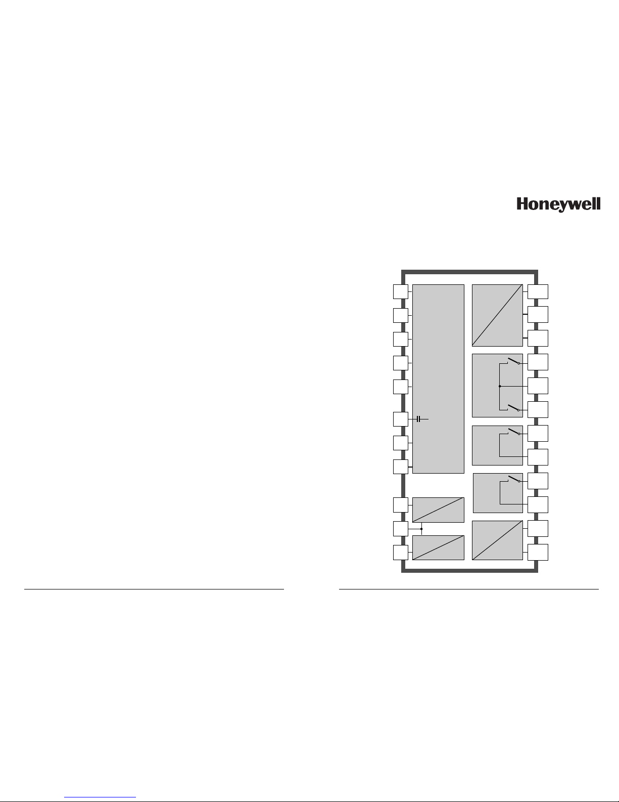
Overview of APT4000PH
1
2
3
E
D
C
4
5
6
7
8
9
10
11
12
13
14
15
16
17
18
19
20
pH / mV /
temp
input
Hold
input
Control
input
Output 1
Output 2
Alarm
Wash
Power
Glass
electrode
Reference
electrode
Auxiliary
electrode
RTD
RTD
Shield
+ DURAFET II
– DURAFET II
Hold
Hold/
CONTROL
CONTROL
+ Output 1
- Output 1/2
+ Output 2
Relay 1
Relay 1/2
Relay 2
Alarm
Alarm
Wash
Wash
Power
Power
R1
R2
Power supply
for
DURAFET II
electrode
Page 5
8
APT4000PH
Package contents
Check the shipment for transport damage and completeness.
The package should contain:
• Front unit of APT4000PH
• Lower case
• Bag containing small parts
• Instruction manual
• Specific test report
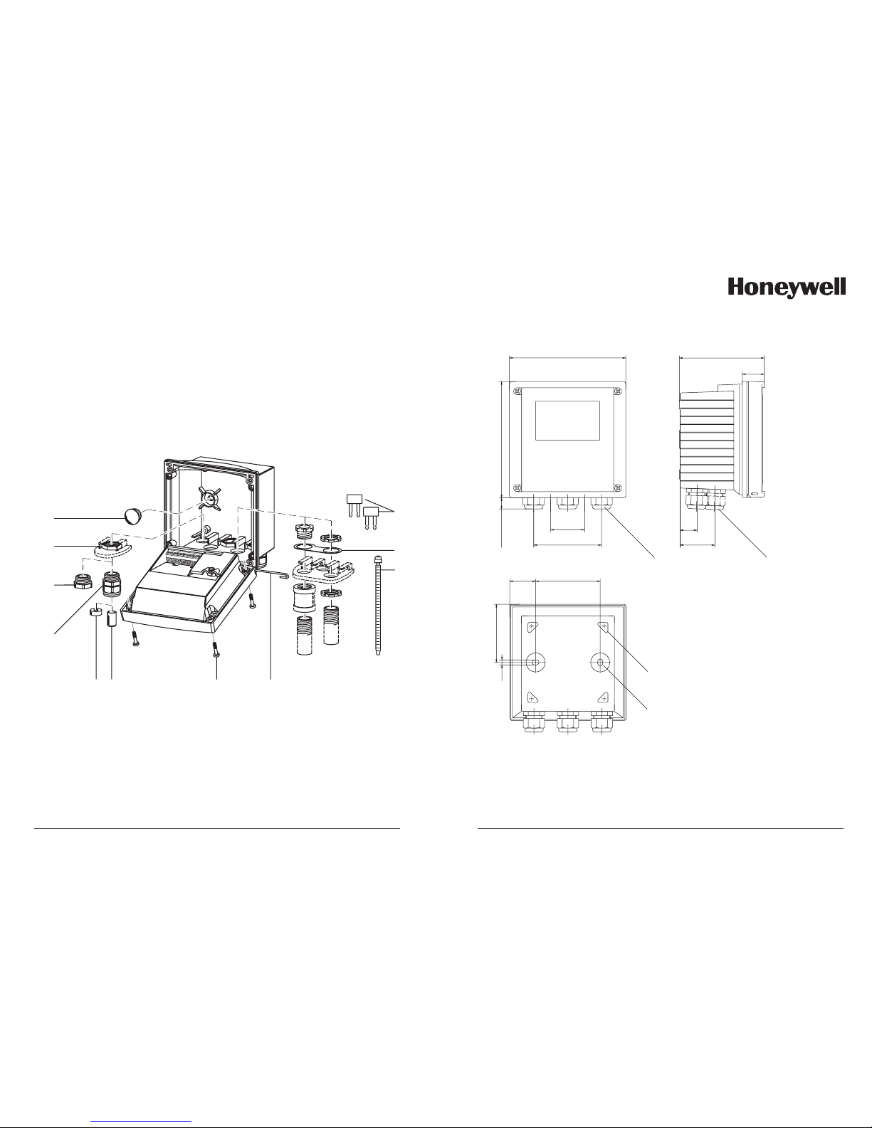
Assembly
11
10
9
8
76 5
4
1
2
3
6 Sealing inserts (1 piece)
7 Rubber reducer (1 piece)
8 Cable glands (3 pieces)
9 Filler plugs (3 pieces)
10 Hexagon nuts (5 pieces)
11 Sealing plugs (2 pieces),
for sealing in case of wall mounting
1 Jumper (2 pieces)
2 Washer (1 piece),
for conduit mounting: Place washer
between enclosure and nut
3 Cable ties (3 pieces)
4 Hinge pin (1 piece),
insertable from either side
5 Enclosure screws (4 pieces)
Fig. 1: Assembling the enclosure
9
Mounting plan
144
144
15
42
84
80
32
21
43
105
27
72
6,2
12
3
4
1 Cable gland (3 pieces)
2 Breakthroughs for cable gland
or conduit 1/2”,
dia 21.5 mm (2 breakthroughs)
Conduits not included!
3 Breakthroughs for pipe mounting
(4 breakthroughs)
4 Breakthroughs for wall mounting
(2 breakthroughs)
Fig. 2: Mounting plan
All dimensions in mm.
Page 6
10
APT4000PH
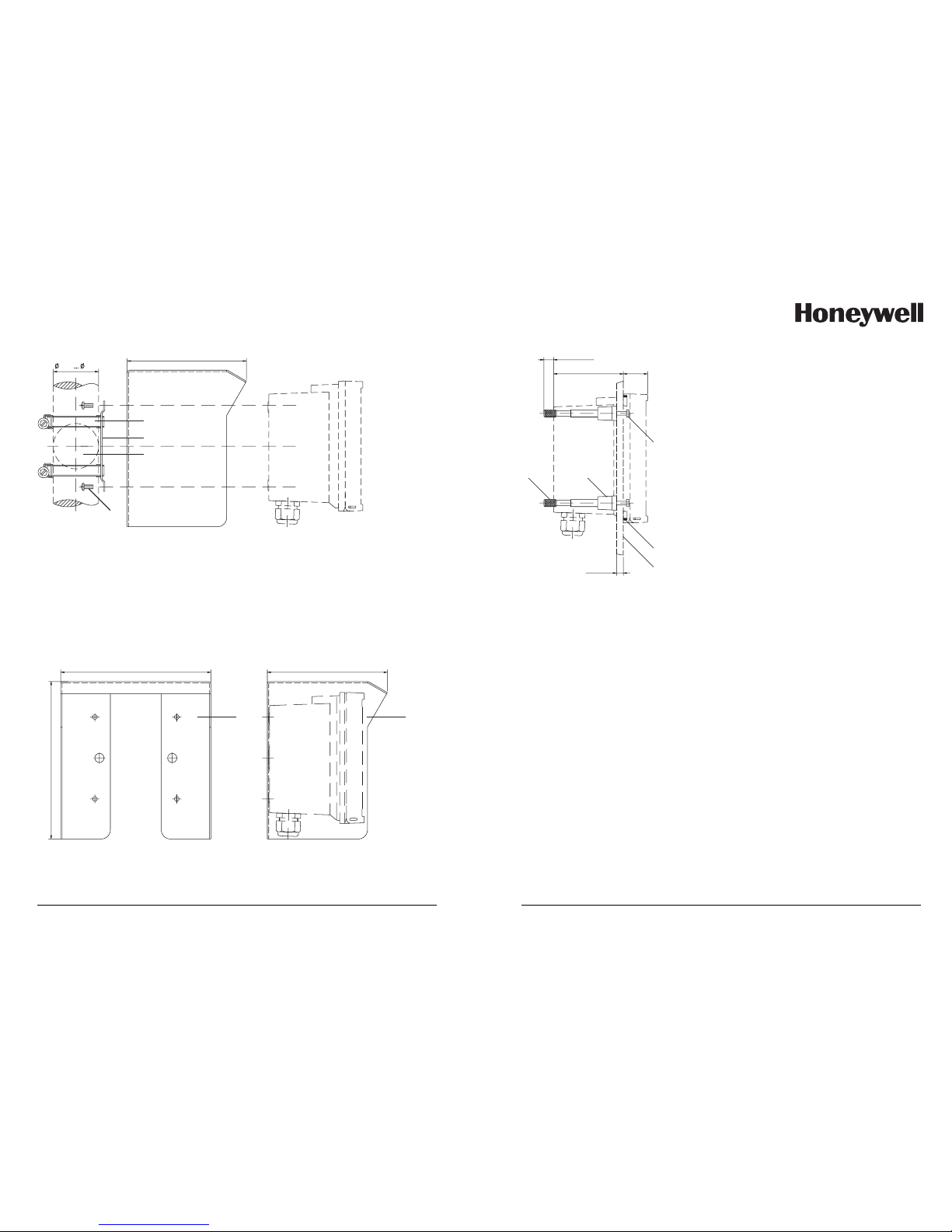
40 60
132
1
2
3
4
5
Fig. 3: 51205988-001 pipe-mount kit
1 512005989-001 protective hood (if required)
2 Hose clamps with worm gear drive to DIN 3017 (2 pieces)
3 Pipe-mount plate (1 piece)
4 For vertical or horizontal posts or pipes
5 Self-tapping screws (4 pieces)
1
132165
173
1
Fig. 4: 51205989-001 protective hood for wall and
pipe mounting
Pipe mounting, panel mounting
All dimensions in mm.
11
1
2
3
45
max. 25
78 27
1...22
1 Screws (4 pieces)
2 Gasket (1 piece)
3 Control panel
4 Span pieces (4 pieces)
5 Threaded sleeves (4 pieces)
Fig. 5: 51205990-001 panel-mount kit
All dimensions in mm.
Page 7

12
APT4000PH
Installation and connection
Information on installation
Caution!
• The analyzer may only be installed by trained experts
in accordance with this instruction manual
and as per applicable local and national codes.
• Be sure to observe the technical specifications and
input ratings.
• Be sure not to notch the conductor when stripping the
insulation.
• Before connecting the analyzer to the power supply,
make sure that its voltage lies within the range
20.5 to 253 V AC/DC.
• When commissioning, a complete configuration must be
carried out by the system administrator.
The terminals are suitable for single wires and flexible leads up to
2.5 mm
2
(AWG 14).
Terminal assignments
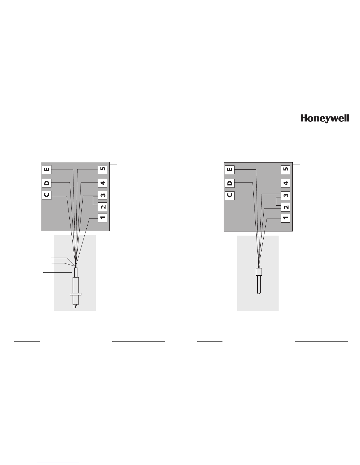
Fig. 6: Terminal assignments APT4000PH
13
1 ESD shield covering the signal inputs (Screw off for assembly)
Note: The cable shield must end under the ESD shield.
(Cut lines if required)
2 Terminals for temperature probe and outer shield
3 Terminals for electrode
4 Connection of power supply
Fig. 7: Information on installation, rear side of analyzer
1
3
2
4
The connections to the analyzer are incendive and
must be installed in accordance with the National
Electric Code (ANSI-NFPA 70) Division 2 hazardous
(classified) location incendive wiring techniques.
Division 2 wiring
Page 8
14
APT4000PH
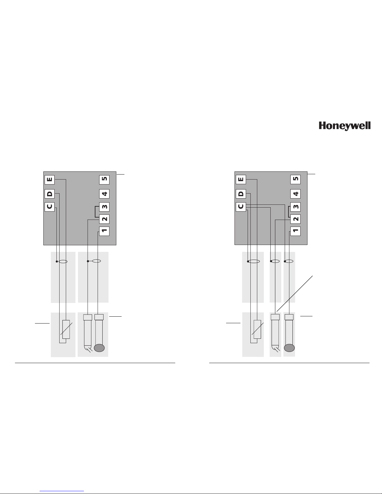
Typical wirings pH
Temperature
probe
Combination
pH
electrode
Example 1:
pH measurement with monitoring of glass electrode
Sensor connections
APT4000PH
15
Temperature
probe
Glass
electrode
Example 2:
pH measurement with monitoring of glass electrode and reference electrode
Sensor connections
APT4000PH
Reference
electrode
Page 9
16
APT4000PH
Typical wirings
Example 3:
pH measurement with DURAFET II electrode
orange
red
wt
rd/bk
yw
gn
bu
bk
wt/bk
Do not
connect:
Sensor connections
APT4000PH
Must use cap
adapter cable
17
Example 4:
pH measurement with MEREDIAN electrode
wt
wt
wt/bk
or
core
Sensor connections
APT4000PH
Page 10

18
APT4000PH
ORP wirings
Example 5:
ORP measurement without monitoring of
reference electrode
Temperature
probe
Sensor connections
APT4000PH
19
Example 6:
ORP measurement with monitoring of
reference electrode
Temperature
probe
Sensor connections
APT4000PH
Page 11
20
APT4000PH
Protective wiring of relay contacts
Relay contacts are subjected to electrical erosion. Especially
with inductive and capacitive loads, the service life of the contacts will be reduced. For suppression of sparks and arcing,
components such as RC combinations, nonlinear resistors,
series resistors and diodes should be used.
1
2
3
1
2
3
Typical AC applications
with inductive load
1 Load
2 RC combination, e.g. RIFA PMR 209
Typical RC combinations
for 230 V AC:
Capacitor 0.1µF / 630V,
Resistor 100 Ohms / 1 W
3 Contact
Protective wiring of switching outputs
21
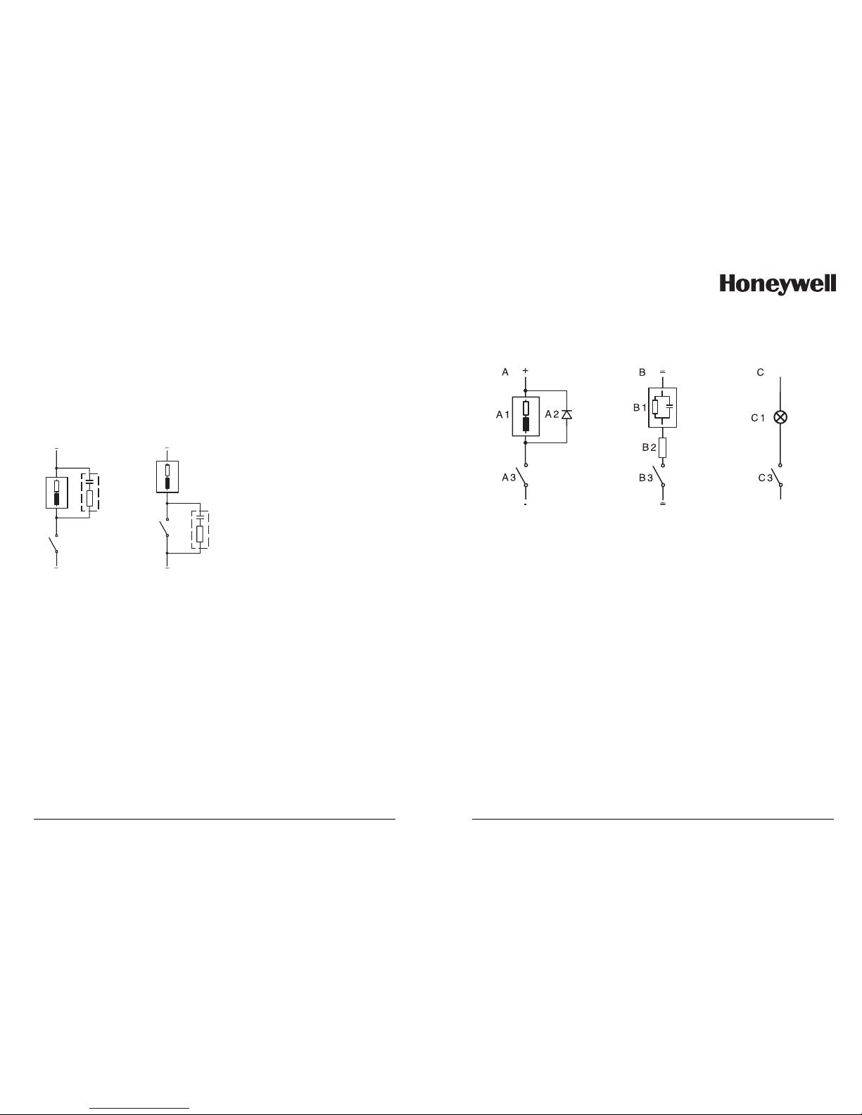
A: DC application with inductive load
B: AC/DC applications with capacitive load
C: Connection of incandescent lamps
A1 Inductive load
A2 Free-wheeling diode, e.g. 1N4007 (Observe polarity)
A3 Contact
B1 Capacitive load
B2 Resistor, e.g. 8 Ohms/1 W at 24 V / 0.3 A
B3 Contact
C1 Incandescent lamp, max 60 W / 230 V, 30 W / 115 V
C3 Contact
Warning!
Make sure that the maximum ratings of the relay
contacts are not exceeded even during switching!
Typical protective wiring measures
Page 12
22
APT4000PH
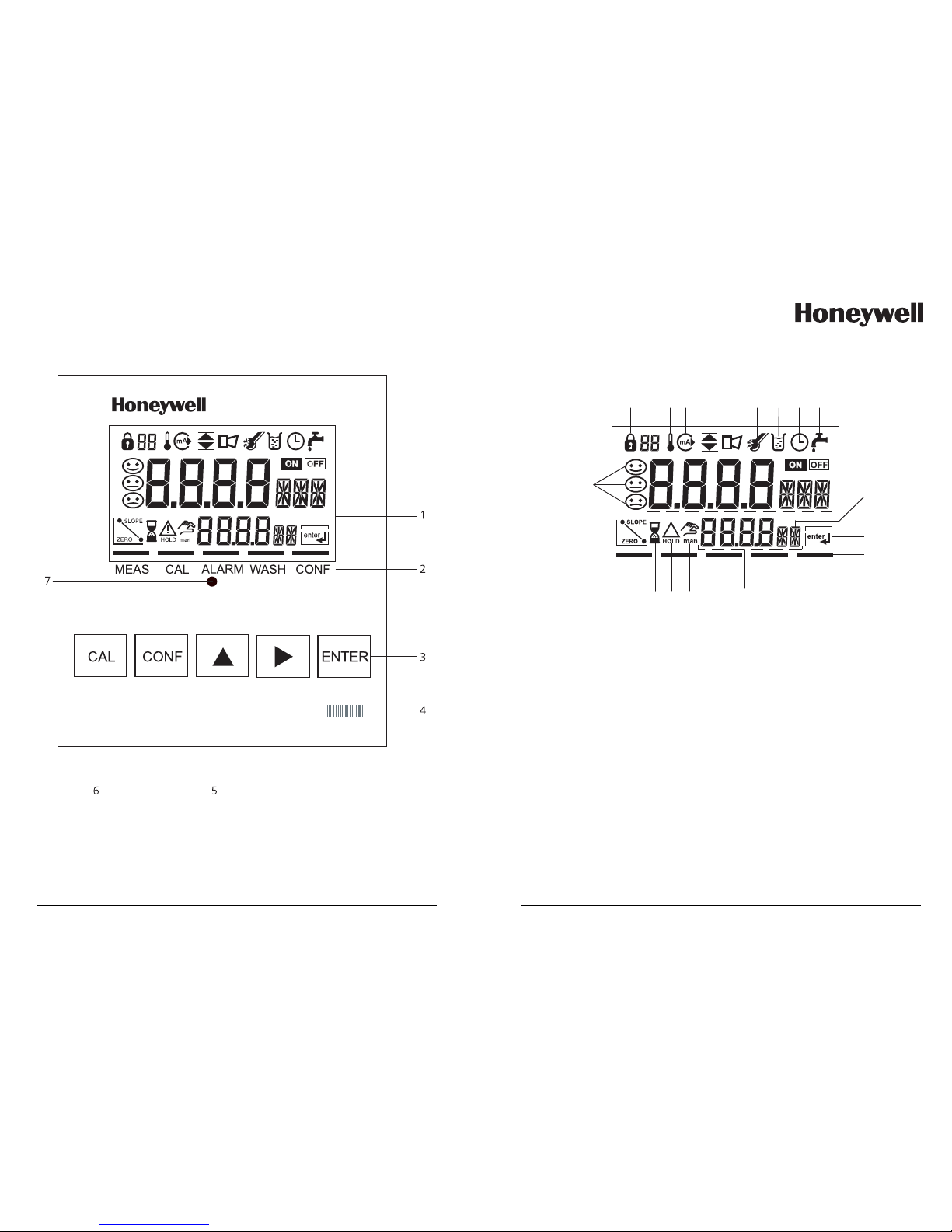
User interface and display
1 Display
2 Mode indicators (no keys),
from left to right:
- Measuring mode
- Calibration mode
- Alarm
- Wash contact active
- Configuration mode
3 Keypad
4 Coding
5 Rating plate
6 Model designation
7 Alarm LED
User interface
23
1234 56 78910
11
12
13
1617
20
18
19
15
14
1 Mode code entry
2 Display of meas. variable *
3 Temperature
4 Current output
5 Limit values
6 Alarm
7 Sensocheck
8 Calibration
9 Interval/response time
10 Wash contact
11 Measurement symbols
12 Proceed with ENTER
13 Bar for identifying the device
status, above mode indicators,
from left to right:
- Measuring mode
- Calibration mode
- Alarm
- Wash contact active
- Configuration mode
14 Lower display
15 Manual temp indicator
16 Hold mode active
17 Waiting time running
18 Electrode data
19 Main display
20 Sensoface
* Not in use
Display
Page 13

24
APT4000PH
Operation: Keypad
Start, end calibration
Start, end configuration
Select digit position
(selected position flashes)
Edit digit
• Calibration:
Continue in program sequence
• Configuration: Confirm entries,
next configuration step
• Measuring mode: Display output current
Cal Info, display of asymmetry potential
and slope
Error Info, display last error message
Start GainCheck device self-test
+
25
Sensoface provides information on the electrode condition. The asymmetry potential (zero), slope and
response time during calibration are evaluated. The
three Sensoface indicators provide the user with information about wear and required maintenance of the
sensor.
Note: When measuring with DURAFET electrodes,
Sensocheck is not active.
GainCheck device self test
A display test is carried out, the software version is displayed
and the memory and measured value transfer are checked.
Start GainCheck device self-test:
Automatic device self-test
The automatic device self-test checks the memory and measured-value transfer. It runs automatically in the background at
fixed intervals.
+
Safety functions
Sensocheck, Sensoface sensor monitoring
Sensocheck continuously monitors the sensor and leads.
Sensocheck can be switched off (Configuration, Pg 51).
Page 14

26
APT4000PH
Safety functions
Hold mode
Display:
The Hold mode is a safety state during configuration and calibration. Output current is frozen (LAST) or set to a fixed value
(Fix). Alarm and limit contacts are disabled.
If the calibration or configuration mode is exited, the
APT4000PH remains in the Hold mode for safety reasons.
This prevents undesirable reactions of the connected peripherals due to incorrect configuration or calibration. The measured
value and “Hold” are displayed alternately. The APT4000PH
only returns to measuring mode after ENTER is pressed and a
waiting time of 20 s has passed.
27
To activate the Hold mode from outside
The Hold mode can be activated from outside by sending a
signal to the Hold input (e.g. from the process control system).
Hold active
Hold inactive
10 ... 30 V AC/DC 0 ... 2 V AC/DC
6
7
Hold
input
Process control system (PCS)
Power supply
12...24 V AC/DC
APT4000PH
Page 15
28
APT4000PH
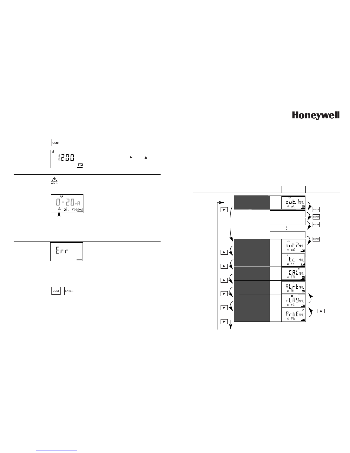
Configuration
In the Configuration mode you set the analyzer parameters.
Activate with CONF
Enter mode code “1200”
Edit parameter with and ,
confirm/continue with ENTER.
(End with CONF ENTER.)
During configuration the
APT4000PH remains in the Hold
mode for reasons of safety. The
output current is frozen (at its last
value or at a preset fixed value,
depending on the configuration),
limit and alarm contacts are inactive.
The controller is in the configured
state, Sensoface is off, mode indicator “Configuration” is on.
Activate
Hold
Input errors
The configuration parameters are
checked during the input. In the
case of an incorrect input “Err” is
displayed for approx. 3 s. The
incorrect parameters cannot be
stored. Input must be repeated.
End
End with CONF. The measured
value and Hold are displayed alternately, “enter” flashes. End Hold
mode with ENTER.
The display shows the measured
value. The output current remains
frozen for another 20 s (Hold icon
on, “hourglass” flashes).
Hold icon
29
Menu group
Code
Output 1
o1.
Output 2
o2.
Temperature
compensation
tc.
Calibration mode
CA.
Alarm
settings
AL.
Relay / Controller
rL.
Rinsing and calibration probes
Pb.
Display
Select menu group
Previous
menu group:
Menu structure of configuration
Menu item 1
Menu item 2
Menu item ...
The configuration steps are assigned to different menu groups.
With the arrow keys you can jump between the individual menu
groups.
Each menu group contains menu items for setting the parameters.
Pressing ENTER opens a menu item. The values are edited using the
arrow keys. Pressing ENTER confirms/stores the settings.
Return to measurement: Press CONF.
Select menu item
Page 16

30
APT4000PH
Overview of configuration steps
Time constant of output filter
22 mA signal in the case of error
Signal behavior during Hold
Enter fixed value
out2
Output 2
o2.
Select temperature unit
Select temperature probe
Select current range
Enter current beginning
Enter current end
Time constant of output filter
22 mA signal in the case of temp error
Signal behavior during Hold
Enter fixed value
tc.
Temperature compensation
tc.
Temp detection during meas
Temp detection during cal
Enter TC process medium
CAL
Calibration mode
CA.
Select calibration mode
Enter cal timer interval
Menu
Code
out1
Output 1
o1.
Select measured variable
Select electrode type
Select current range
Enter current beginning
Enter current end
Selection / Default
pH / ORP
GLAS EL / FEt EL
0-20 mA / 4-20 mA
XX.XX pH / XXXX mV (00.00 pH)
XX.XX pH / XXXX mV (14.00 pH)
0 .... 120 SEC (0 SEC )
ON / OFF
LAST / Fix
000.0 ... 021.0 mA (021.0 mA)
°C / °F
Pt100/Pt1000/NTC30/ NTC8.55
0-20 mA / 4-20 mA
XXX.X (000.0 °C )
XXX.X (100.0 °C )
0 ... 120 (0 SEC)
ON / OFF
LAST / Fix
000.0 ... 021.0 mA (021.0 mA)
Auto/man (man: XXX.X°C (025.0°C))
Auto/man (man: XXX.X°C (025.0°C))
-19.99 ... +19.99%/K (00.00%/K)
-04-BUF / MAN / DAT
0000 ... 9999 h (0000 h)
31
Menu
Code
Selection / Default
ALrt
Alarm settings
AL.
Select Sensocheck
Enter alarm delay
LED in Hold mode
rLAY
Relay 1/2: Limit values, controller
rL.
Select limit function / controller
Select contact function
L1.
Select contact response
Enter switching point
Enter hysteresis
Enter delay
Select contact function
L2.
Enter controller setpoint
Ct.
Enter neutral zone
(P) Controller gain K
P
(I) Reset time T
R
(D) Rate time T
D
Controller
PLC: Pulse length
PFC: Pulse frequency
Select Hold behavior
PrbE
Rinsing and cleaning probes
Pb.
Select cleaning / calibration probe
Rinsing interval
rinse
Rinse duration
Contact response
Cleaning interval
EASYCLN
Select contact response
Enter switching point
Enter hysteresis
Enter delay
Calibration interval
Lock cleaning / calibration interval
ON /
OFF
0000 ... 0600 SEC (0010 SEC)
ON / OFF
LiMIT / CtROL
Lo / Hi
N/O / N/C
XX.XX pH / XXXX mV
(00.00 pH)
XX.XX pH / XXXX mV
(00.50 pH)
0000 ... 9999 SEC (0010 SEC)
Lo / Hi
XX.XX pH / XXXX mV
(07.00 pH)
XX.XX pH / XXXX mV
(01.00 pH)
0010 ... 9999 % (
100 %
)
0000 ... 9999 SEC (0000 SEC)
0000 ... 9999 SEC (0000 SEC)
PLC / PFC
0001 ... 0600 SEC (0010 SEC)
0001 ... 0180 /min (0060 /min)
Y LAST / Y Off
EASYCLN / rinse
000.0 ... 999.9 h (
000.0 h
)
0000 ... 1999 SEC (0060 SEC)
N/O /
N/C
000.0 ... 999.9 h (
000.0 h
)
N/O / N/C
XX.XX pH / XXXX mV(14.00 pH
)
XX.XX pH / XXXX mV
(00.50 pH)
0000 ... 9999 SEC (
0010 SEC
)
000.0 ... 999.9 h (000.0 h)
ON / OFF
Page 17

32
APT4000PH
Configuration
Output 1
Select type of electrode. Measurement procedure.
Select measured variable
Select electrode type
Select 0-20 / 4-20 mA
Enter current beginning
Enter current end
Set output filter
22 mA in the case of error
Hold mode
End:
Press CONF, then ENTER
code
Output 1
o1.
Display
Menu group
Select menu item
33
Note: Characters represented in gray are flashing and can be edited.
Code
Display
Action
Choices
o1.
Select configuration
(Press CONF.)
Enter mode code “1200”
(Select position with key and
edit number with key.
When the display reads “1200”,
press ENTER to confirm.)
The APT4000PH is in Hold mode
(Hold icon is on).
Select measured variable pH/ORP
Select with key
Proceed with ENTER
pH/ORP
Only with pH selected:
Select electrode type:
• ISFET electrode
• Glass electrode
Select with key
Proceed with ENTER
FEt
(Glas)
After correct input a welcome text (ConF) is displayed for approx. 3 s
Page 18
34
APT4000PH
Configuration
Output 1
Output current range. Current beginning. Current end.
Select measured variable
Select electrode type
Select 0-20 / 4-20 mA
Enter current beginning
Enter current end
Set output filter
22 mA in the case of error
Hold mode
End:
Press CONF, then ENTER
Code
Output 1
o1.
Display
Menu group
Select menu item
35
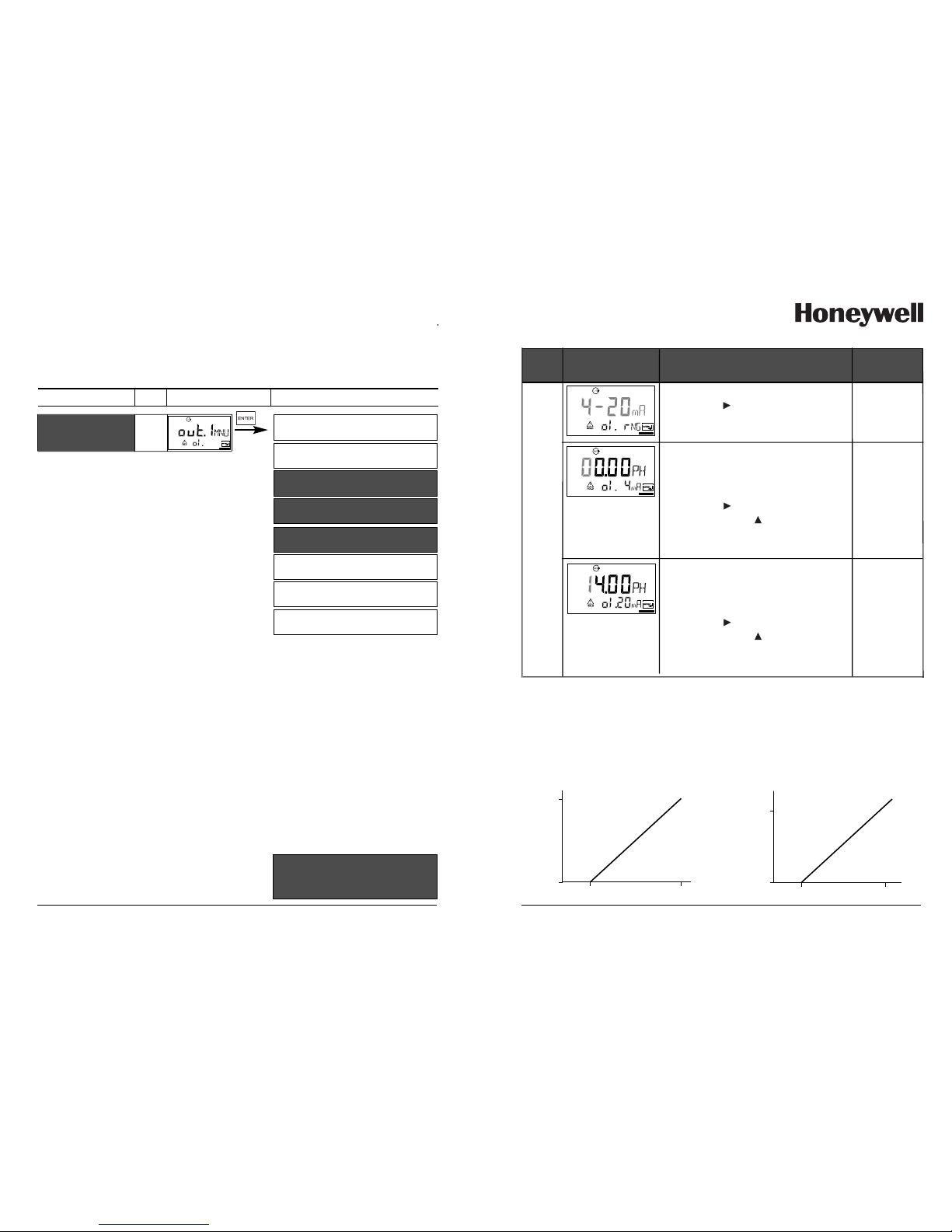
Code
4–20 mA
(0–20 mA)
Display
Action
Choices
o1.
Set output current range
Select with key
Proceed with ENTER
Current beginning
Enter lower end of scale, depending
on measured variable selected
(pH or ORP)
Select with key,
edit number with key,
proceed with ENTER
00.00 pH
(pH:
-2 ... 16)
/ (ORP:
-1500 mV
to
+1500 mV)
Current end
Enter upper end of scale, depending
on measured variable selected
(pH or ORP)
Select with key,
edit number with key,
proceed with ENTER
14.00 pH
(pH:
-2 ... 16)
/ (ORP:
-1500 mV
to
+1500 mV)
Output current
[pH]
204
14
0
Assignment of measured values:
Current beginning and current end
[pH]
204
7
5
[mA]
Example 1: Range pH 0 to 14 Example 2: Range pH 5 to 7
Advantage: Higher resolution in
range of interest
[mA]
Output current
Page 19

36
APT4000PH
Configuration
Output 1
Time constant of output filter
Select measured variable
Select electrode type
Select 0-20 / 4-20 mA
Enter current beginning
Enter current end
Set output filter
22 mA in the case of error
Hold mode
End:
Press CONF, then ENTER
Code
Output 1
o1.
Display
Menu group
Select menu item
37
0 SEC
(0 to
120 SEC)
Code
Display Action
Choices
o1.
Time constant of output filter
Default setting: 0 s (inactive).
To specify a time constant:
Select with key,
edit number with key,
proceed with ENTER
Time constant of output filter
To smoothen the current output, a low-pass filter with
adjustable filter time constant can be switched on. When there
is a jump at the input (100 %), the output level is 63 % after
the time constant has been reached.
The time constant can be set from 0 to 120 s.
If the time constant is set to 0 s, the current output follows the
input.
Note:
The filter only acts on the current output, not on the display, the
limit values, or the controller!
Time constant 0 to 120 s
Page 20

38
APT4000PH
Configuration
Output 1
Output current during Error and Hold.
Select measured variable
Select electrode type
Select 0-20 / 4-20 mA
Enter current beginning
Enter current end
Set output filter
22 mA in the case of error
Hold mode
End:
Press CONF, then ENTER
Code
Output 1
o1.
Display
Menu group
Select menu item
39
OFF
(ON)
Code
Display
Action
Choices
o1.
22 mA signal for error message
Select with key
Proceed with ENTER
Output signal during Hold
LAST:
During Hold the last measured value
is maintained at the output
FIX:
During Hold a value (to be entered) is
maintained at the output.
Select with key
Proceed with ENTER
LAST
(FIX)
Only with FIX selected:
Enter current which is to flow at the
output during Hold
Select with key,
edit number with key,
proceed with ENTER
021.0 mA
(000.0 to
021.0 mA)
Output signal for Hold:
Output current
[mA]
Output signal Hold
Setting FIX = 21.0 mA
Hold active
21
4
Output signal HOLD
Setting LAST
Hold active
Page 21

40
APT4000PH
Configuration
Output 2
Temperature unit and probe. Output current.
Select °C/°F
Select temperature probe
Select 0-20 / 4-20 mA
Enter current beginning
Enter current end
Set output filter
22 mA for temp error
Hold mode
End:
Press CONF, then ENTER
Code
Display
Menu group
Select menu item
Output 2
o2.
41
°C
(°F)
Code
Display
Action
Choices
o2.
Specify temperature unit
Select with key
Proceed with ENTER
Select temperature probe
Select with key
Proceed with ENTER
NTC8.55
(NTC30,
PT100,
PT1000)
4–20 mA
(0–20 mA)
Set output current range
Select with key
Proceed with ENTER
Current beginning:
Enter lower end of scale.
Select with key, edit number with
key, proceed with ENTER
000.0 °C
(XXX.X)
Current end:
Enter upper end of scale.
Select with key, edit number with
key, proceed with ENTER
100.0 °C
(XXX.X)
Output current
Process temperature
204
100
0
Process temperature: Current beginning and current end
Process temperature
204
70
50
[mA]
Example 1: Range 0 to 100 °C Example 2: Range 50 to 70 °C.
Advantage: Higher resolution in
range of interest
[°C]
[°C]
[mA]
Page 22

42
APT4000PH
Configuration
Output 2
Time constant of output filter.
Select °C/°F
Select temperature probe
Select 0-20 / 4-20 mA
Enter current beginning
Enter current end
Set output filter
22 mA for temp error
Hold mode
End:
Press CONF, then ENTER
Output 2
o2.
Code
Display
Menu group
Select menu item
43
0 SEC
(0 to
120 SEC)
Code
Display
Action
Choices
o2.
Time constant of output filter
Default setting: 0 s (inactive).
To specify a time constant: Select
with key, edit number with
key, proceed with ENTER
Time constant of output filter
To smoothen the current output 2, a low-pass filter with
adjustable filter time constant can be switched on. When there
is a jump at the input (100 %), the output level is 63 % after
the time constant has been reached.
The time constant can be set from 0 to 120 s.
If the time constant is set to 0 s (default), the current output follows the input.
Note:
The filter only acts on the current output, not on the display!
Time constant 0 to 120 s
Page 23

44
APT4000PH
Configuration
Output 2
Temperature error. Output current during Hold.
Select °C/°F
Select temperature probe
Select 0-20 / 4-20 mA
Enter current beginning
Enter current end
Set output filter
22 mA for temp error
Hold mode
End:
Press CONF, then ENTER
Output 2
o2.
Code
Display
Menu group
Select menu item
45
OFF
(ON)
Code
Display
Action
Choices
o2.
22 mA signal for error message
Select with key
Proceed with ENTER
Output signal during Hold
LAST:
During Hold the last measured value
is maintained at the output
FIX:
During Hold a value (to be entered)
is maintained at the output
Select with key
Proceed with ENTER
LAST
(FIX)
Only with FIX selected:
Enter current which is to flow at the
output during Hold
Select with key,
edit number with key,
proceed with ENTER
021.0 mA
(000.0 to
021.0 mA)
Output signal during Hold:
Output current
[mA]
Output signal Hold
Setting FIX = 21.0 mA
Hold active
21
4
Output signal Hold
Setting LAST
Hold active
Page 24

46
APT4000PH
Configuration
Temperature compensation
Temp detection for meas/cal. TC process medium
Temp during measurement
Temp during calibration
Enter TC process medium
End:
Press CONF, then ENTER
Temperature
compensation
tc.
Code
Display
Menu group
Select menu item
47
AUT
(MAN)
Code
Display
Action
Choices
tc.
Select temp detection during measurement (Auto/MAN)
AUTO: Temp detection with temperature probe
MAN: Manual temperature input
Select with key,
proceed with ENTER
Only with manual temp detection
selected (MAN)
Enter temperature.
Select position with key,
edit number with key,
proceed with ENTER
25 °C
(XXX.X)
Select temp detection during
calibration (Auto/MAN)
Select with key,
proceed with ENTER
AUT
(MAN)
Only with manual temp detection
selected (MAN)
Enter temperature.
Select position with key,
edit number with key,
proceed with ENTER
For pH measurement only:
Enter temperature compensation of
process medium
Select position with key,
edit number with key,
proceed with ENTER
00.00
%/K
(-19.99
to 19.99
%/K)
25 °C
(XXX.X)
Page 25

48
APT4000PH
Configuration
Calibration mode
Calibration mode
Cal timer interval
Code
Display
Menu group
Select menu item
Calibration mode
CA.
End:
Press CONF, then ENTER
49
-O4-BUF
(-01-BUF/
-02-BUF/
-03-BUF/
-04-BUF/
-05-BUF/
-06-BUF/
-07-BUF/
MAN/
DAT)
Code
Display
Action
Choices
CA.
For pH measurement only:
Select calibration mode
BUF: Calibration with Calimatic automatic buffer selection.
To do so, you must select your buffer
set:
-01- BUF: Mettler-Toledo
-02-BUF: Merck Titrisols, Riedel Fixanals
-03-BUF: Ciba (94)
-04-BUF: NIST technical buffers
-05-BUF: NIST standard buffers
-06-BUF: HACH buffers
-07-BUF: WTW technical buffers
MAN: Calibration with
manual buffer entry
DAT: Entry of asymmetry potential
and slope of premeasured electrodes
Select with key,
proceed with ENTER
Enter calibration interval:
Entry of time interval within which
the analyzer is to be calibrated.
With a time interval of 0000 hrs the
calibration timer is not active.
Select position with key,
edit number with key,
proceed with ENTER
0000 h
(0000 to
9999 h)
Page 26

50
APT4000PH
Configuration
Alarm settings
Select Sensocheck
Delay
LED in Hold mode
Code
Display
Menu group
Select menu item
Alarm
settings
AL.
End:
Press CONF, then ENTER
15
16
Alarm
Alarm contact
The alarm contact is closed during normal operation
(N/C). It opens in the case of alarm or power outage.
As a result, a failure message is provided even in the
case of line breakage (fail-safe behavior). For contact ratings, see Specifications.
Error messages can also be signaled by a 22 mA output
current (see Pg 39,
The operating behavior of the alarm contact is shown on
Pg 90.
The alarm delay acts on the LED, the 22 mA signal
and the alarm contact.
45,
86).
51
Code
Display
Action
Choices
ON /
OFF
AL.
Select Sensocheck
(continuous monitoring of glass and
reference electrode – not available
with DURAFET II pH electrode)
Select with key,
proceed with ENTER
Alarm delay
Select with key, edit number with
key, proceed with ENTER
0010 SEC
(0000 to
0600 SEC)
LED in Hold mode
Select with key, edit number with
key, proceed with ENTER
ON /
OFF
Parameter setting
Alarm Hold
ON
on flashes
OFF
flashes off
LED state:
Page 27

52
APT4000PH
Configuration
Limit function
Relay 1
Contact function
Contact response
Enter switching point
Enter hysteresis
Delay
Relay 2 menu group
Controller menu group
L1.
L2.
Ct.
Relay / Controller
rL.
Code
Display
Menu group
Select menu item
End:
Press CONF, then ENTER
53
LiMIT
(CtROL)
Code
Display
Action
Choices
rL.
Use of relays:
• Limit function (LiMIT)
• Controller (CtROL)
Select with key,
proceed with ENTER
Note: Selecting CtROL leads to
Controller menu group Ct.
Lo
(Hi)
Limit 1 function , see Page 55.
Select with key,
proceed with ENTER
Limit 1 contact response
N/C: normally closed contact
N/O: normally open contact
Select with key,
proceed with ENTER
N/O
(N/C)
Limit 1 switching point
Select with key, edit number with
key, proceed with ENTER
00.00 pH
(
XX.XX pH
XXXX mV)
Limit 1 hysteresis
Select with key, edit number with
key, proceed with ENTER
00.50 pH
(
XX.XX pH
XXXX mV)
Limit 1 delay
The contact is activated with
delay (deactivated without delay)
Select with key, edit number with
key, proceed with ENTER
0010 SEC
(
0 to
9999 SEC)
L1.
Page 28

54
APT4000PH
Configuration
Limit function
Relay 2
Relay 1 menu group
Contact function
Contact response
Enter switching point
Enter hysteresis
Delay
Controller menu group
L1.
L2.
Ct.
Relay / Controller
rL.
Code
Display
Menu group
Select menu item
End:
Press CONF, then ENTER
55
Code
Display Action
Choices
L2.
Hi
(Lo)
Select Limit 2, see Fig. below.
Select with key,
proceed with ENTER
Limit 2 contact response
N/C: normally closed contact
N/O: normally open contact
Select with key,
proceed with ENTER
N/O
(N/C)
Limit 2 switching point
Select with key, edit number with
key, proceed with ENTER
14.00 pH
(
XX.XX pH
XXXX mV)
Limit 2 hysteresis
Select with key, edit number with
key, proceed with ENTER
00.50 pH
(
XX.XX pH
XXXX mV)
Limit 2 delay
The contact is activated with
delay (deactivated without delay)
Select with key, edit number with
key, proceed with ENTER
0010 SEC
(
0 to
9999 SEC)
Limit Lo
Hysteresis +
Switching
point
Contact
0
1
Signal
Limit Hi
Hysteresis -
Signal
Switching
point
Contact
0
1
Page 29

56
APT4000PH
Configuration
Controller
(for description see Pg 82 and the following)
Setpoint. Neutral zone
Relay 1 menu group
Relay 2 menu group
Controller setpoint
Enter neutral zone
(P) Controller gain
(I) Reset time TR
(D) Rate time TD
Pulse length/Pulse frequency
PLC: Pulse length
PFC: Pulse frequency
Hold behavior
L1.
L2.
Ct.
Relay / Controller
rL.
Code
Display
Menu group
Select menu item
End:
Press CONF, then ENTER
01.00 pH
(
XX.XX pH /
XXXX mV)
07.00 pH
(
XX.XX pH /
XXXX mV)
Setpoint
Select with key, edit number with
key, proceed with ENTER
Neutral zone (dead band)
Select with key, edit number with
key, proceed with ENTER
Controller: P-action component
Select with key, edit number with
key, proceed with ENTER
57
Code
Display
Action
Choices
Ct.
0100 %
(0010 to
9999 %)
Controller: I-action component (reset
time). Select with key, edit number
with key, proceed with ENTER
0000 SEC
(0000 to
9999 SEC)
Controller: D-action component
(Rate time).
Select with key, edit number with
key, proceed with ENTER
0000 SEC
(0000 to
9999 SEC)
Pulse length/Pulse frequency
Select with key,
proceed with ENTER
PLC
(PFC)
PLC: Pulse length
Select with key, edit number with
key, proceed with ENTER
0010 sec
(0001 to
0600 SEC)
PFC: Pulse frequency
Select with key, edit number with
key, proceed with ENTER
0060
/min
(0001 to
0180 /min)
Behavior during Hold
Select with key,
proceed with ENTER
Y LAST
(Y Off)
Page 30

58
APT4000PH
Configuration
Control of rinsing and calibration probes
Rinsing/calibration probe
Rinsing interval
Rinse duration
Contact response
Cleaning interval
Rinsing and calibration probes
Pb.
Code
Display
Menu group
Select menu item
Calibration interval
rinse
(EASYCLN)
EASYCLN:
see opposite
page
Code
Display
Action (rinsing probe)
Selection
Pb.
Control of:
• Rinsing probe (rinse)
• Calibration probe (EasyClean)
Select with key
Proceed with ENTER
000.0 h
(
XXX.X h)
Rinsing interval
Select with key, edit number
with key, proceed with ENTER
Rinse duration
Select with key, edit number
with key, proceed with ENTER
0060 s
(0000 to
1999 SEC)
Contact type
Select with key
Proceed with ENTER
N/O
(
N/C)
59
EASYCLN
Code
Display
Action (calibration probe)
Selection
Pb.
Calibration probe (EasyClean)
Select with key
Proceed with ENTER
Cleaning interval
(EasyClean only)
Select with key, edit number
with key, proceed with ENTER
000.0 h
(
XXX.X h)
000.0 h
(
XXX.X h)
Calibration interval
(EasyClean only)
Select with key, edit number
with key, proceed with ENTER
Off
(
On)
Lock cleaning (calibration)
interval*
On: The APT4000PH only starts a
cleaning (calibration) interval if the
measured value lies within the tolerated range (Limit Lo/Limit Hi).
*“Lock cleaning (calibration) interval” function:
Limit Hi
Limit Lo
Locked
t
ppb
Locked
The APT4000PH only starts a
cleaning (calibration) interval if the
measured value lies within the
tolerated range (Limit Lo/Limit Hi).
(For limit setting, refer to Pages 53,
55)
Page 31

60
APT4000PH
Parameter set 1/2
Display
Action Remark
Select parameter set 1 or 2.
Select with key,
proceed with ENTER
Switch between parameter sets
Press CONF key,
ENTER code 7654
Select with key, edit number
with key, proceed with ENTER
Wrong settings change
the measurement
properties!
If an invalid code is
entered, the
APT4000PH returns to
measuring mode.
Welcome display
(ConF) appears
for approx. 3 sec
Since the complete device configuration is changed in one step,
there is a security prompt
(No/Yes). When pressing ENTER
directly, the selection is not
stored.
61
Two complete parameter sets are stored in the EEPROM.
As delivered, the two sets are identical but can be edited.
Note:
Fill in your configuration data on the following pages.
Code. Parameter Default setting
o1. pH/ORP unit pH
o1. Electrode type FEt
o1. 0/4-20 mA 4-20 mA
o1. Current beginning 00.00 pH
o1. Current end 14.00 pH
o1. Filter time 0 sec
o1. 22mA signal OFF
o1. Hold behavior LAST
o1. Fix current 021.0 mA
o2. Unit °C / °F °C
o2. Temp probe 8.55 NTC
o2. 0/4...20mA 4-20 mA
o2. Current beginning 000.0 °C
o2. Current end 100.0 °C
o2. Filter time 0 sec
o2. 22mA signal OFF
o2. Hold behavior LAST
o2. Fix current 021.0 mA
tc. TC measurement Auto
tc. Measuring temp 025.0 °C
tc. TC calibration Auto
tc. Calibration temp 025.0 °C
tc. TC medium 00.00 %/K
CA. Cal solution -04-BUF
CA. Cal interval 0000 h
AL. Sensocheck OFF
AL. Alarm delay 0010 sec
AL. LED Hold off
Code. Parameter Default setting
rL. Relay function Limit
L1. Contact function Lo
L1. Contact response N/O
L1. Switching point 00.00 pH
L1. Hysteresis 00.50 pH
L1. Delay 0010 sec
L2. Contact function Hi
L2. Contact response N/O
L2. Switching point 14.00 pH
L2. Hysteresis 00.50 pH
L2. Delay 0010 sec
Ct. Setpoint 07.00 pH
Ct. Neutral zone 01.00 pH
Ct. P action 0100 %
Ct. I action 0000 sec
Ct. D action 0000 sec
Ct. PLC/PFC controller PLC
Ct. Pulse length 0010 sec
Ct. Pulse frequency 0060 /min
Ct. Hold behavior LAST
Pb. EasyCLN/Rinse Rinse
Pb. Rinsing interval 000.0 h
Pb. Rinse duration 0060 sec
Pb. Contact type N/O
Pb. Cleaning interval 000.0 h
Pb. Calibration interval 000.0 h
Pb. Lock interval Off
Default settings of parameter sets
Page 32

62
APT4000PH
Code. Parameter Setting
o1. pH/ORP unit ____________ ____________
o1. Electrode type ____________ ____________
o1. 0/4-20 mA ____________ ____________
o1. Current beginning ____________ ____________
o1. Current end ____________ ____________
o1. Filter time ____________ ____________
o1. 22mA signal ____________ ____________
o1. Hold behavior ____________ ____________
o1. Fix current ____________ ____________
o2. Unit °C / °F ____________ ____________
o2. Temp probe ____________ ____________
o2. 0/4...20mA ____________ ____________
o2. Current beginning ____________ ____________
o2. Current end ____________ ____________
o2. Filter time ____________ ____________
o2. 22mA signal ____________ ____________
o2. Hold behavior ____________ ____________
o2. Fix current ____________ ____________
tc. TC measurement ____________ ____________
tc. Measuring temp ____________ ____________
tc. TC calibration ____________ ____________
tc. TC medium ____________ ____________
CA. Cal solution ____________ ____________
CA. Cal interval ____________ ____________
AL. Sensocheck ____________ ____________
AL. Alarm delay ____________ ____________
AL. LED Hold ____________ ____________
Parameter set – user settings
63
Code. Parameter Setting
rL. Relay function ____________ ____________
L1. Contact function ____________ ____________
L1. Contact response ____________ ____________
L1. Switching point ____________ ____________
L1. Hysteresis ____________ ____________
L1. Delay ____________ ____________
L2. Contact function ____________ ____________
L2. Contact response ____________ ____________
L2. Switching point ____________ ____________
L2. Hysteresis ____________ ____________
L2. Delay ____________ ____________
Ct. Setpoint ____________ ____________
Ct. Neutral zone ____________ ____________
Ct. P action ____________ ____________
Ct. I action ____________ ____________
Ct. D action ____________ ____________
Ct. PLC/PFC controller ____________ ____________
Ct. Pulse length ____________ ____________
Ct. Pulse frequency ____________ ____________
Ct. Hold behavior ____________ ____________
Pb. EasyCLN/Rinse ____________ ____________
Pb. Rinsing interval ____________ ____________
Pb. Rinse duration ____________ ____________
Pb. Contact type ____________ ____________
Pb. Cleaning interval ____________ ____________
Pb. Calibration interval ____________ ____________
Pb. Lock interval ____________ ____________
Page 33

64
APT4000PH
Calibration
Calibration adjusts the analyzer to the electrode.
Activate with CAL
Enter mode code: 1100
Select with key,
edit number with key,
proceed with ENTER
(End with CAL ENTER.)
During calibration the APT4000PH
remains in the Hold mode for reasons of safety. Output current is
frozen (last value or preset fixed
value, depending on configuration),
limit and alarm contacts are inactive. The controller is in the configured state, Sensoface is off, mode
indicator “Configuration” is on.
Activate
Hold
Input errors
The calibration parameters are
checked during the input. In the
case of an incorrect input ”Err” is
displayed for approx. 3 sec. The
incorrect parameters cannot be
stored. Input must be repeated.
End
End with CAL.
The measured value and Hold are
displayed alternately, “enter”
flashes.
Press ENTER to end the Hold mode.
The measured value is displayed.
The output current remains frozen
for another 20 sec (Hold icon on,
“hourglass” flashes).
Hold icon
65
pH calibration
Calibration is used to adapt the analyzer to the individual electrode characteristics, namely asymmetry potential and slope.
Calibration can be performed with Calimatic automatic buffer
recognition, with manual buffer input, by entering premeasured electrode data, or by sampling the product.
When using DURAFET electrodes, you must adjust
the zero point first. Then you can conduct either a
one or a two-point calibration.
Caution
• All calibration procedures must be performed by trained
personnel. Incorrectly set parameters may go unnoticed,
but change the measuring properties.
• The response time of the electrode and temperature probe is
considerably reduced if the electrode is first moved about in
the buffer solution and then held still.
• The analyzer can only operate properly when the buffer
solutions used correspond to the configured set. Other buffer
solutions, even those with the same nominal values, may
demonstrate a different temperature behavior.
This leads to measurement errors.
When using DURAFET electrodes or electrodes with
a zero point other than pH 7, the nominal zero point
must be adjusted each time a new electrode is connected. This
is important if you want to obtain reliable Sensoface messages.
The Sensoface messages issued during all further calibrations
are based on this basic calibration.
Page 34

Display
Action
Remark
If the zero offset of
the electrode is too
large (> ± 200 mV),
the CAL ERR error
message is generated.
In that case the electrode cannot be calibrated.
Zero adjustment
Allows use of electrodes with differing nominal zero (DURAFET II pH electrodes)
Press CAL key,
enter code 1001
Select with key,
edit number with key,
proceed with ENTER
Immerse electrode in a pH 7.00
buffer.
Enter the temperature-corrected
pH value in the range 6.50 to 7.50
using the arrow keys
(see buffer table).
Confirm with ENTER.
APT4000PH is in the
Hold mode.
If an invalid code is
entered, the
APT4000PH returns to
measuring mode.
66
APT4000PH
Ready for calibration
The“CAL”, and “enter” icons are
flashing
Display (3 s)
Stability check:
The measured mV value is displayed.
The “hourglass” icon is flashing.
Note:
Stability check can be
stopped (by pressing
CAL). However, this
reduces calibration
accuracy.
67
Display
Action
Remark
At the end of the adjustment procedure asymmetry potential [mV]
(based on 25 °C) of the electrode
are displayed. Proceed with ENTER
These is not the final
electrode value!
Zero and slope must
be determined with a
complete 2-point calibration (cal 1100)
(see following pages).
Security prompt.
Display of pH value (alternately
with Hold) and temperature,
“enter” flashes, Sensoface is
active.
Place electrode in process.
Press ENTER to end the
zero point calibration.
After end of calibration, the outputs
remain in Hold mode
for approx. 20 sec.
Information on zero adjustment
After having adjusted the nominal zero point, be sure to calibrate the electrode
following one of the procedures as described on the next pages:
• Automatic calibration with Calimatic
• Manual calibration
• Data entry of premeasured electrodes
Page 35

68
APT4000PH
Display
Action
Remark
Buffer recognition
While the “hourglass” icon flashes, the electrode and temperature
probe remain in the first buffer
solution.
Automatic calibration with Calimatic (BUF -xx-)
Temperature detection automatic or manual
Press CAL key, enter code 1100.
Select with key,
edit number with key,
proceed with ENTER
Remove the electrode and
temperature probe, clean them
and immerse them in the first
buffer solution (in any order).
When “Manual temp detection”
has been configured, enter value in
the secondary display using the
arrow keys. Start with
ENTER
.
If an invalid code is
entered, the
APT4000PH returns
to measuring mode.
The response time of
the electrode and
temperature probe is
considerably reduced
if the electrode is
first moved about in
the buffer solution
and then held still.
Buffer recognition terminated,
the nominal buffer value is displayed.
Analyzer in Hold
mode, measured
value frozen.
Sensoface inactive.
The analyzer can only operate properly when the buffer solutions used correspond
to the configured set. Other buffer solutions, even those with the same nominal
values, may demonstrate a different temperature behavior. This leads to measurement errors.
69
Display Action
Remark
Stability check:
The measured mV value is displayed.
To abort stability
check: Press CAL.
(accuracy reduced)
Calibration with the first buffer is
terminated. Remove the electrode
and temp probe from the first
buffer solution and rinse them
thoroughly.
• One-point calibration:
End with CAL.
Slope [%] and asymmetry potential [mV] of the electrode are displayed.
Proceed with ENTER
.
For one-point
calibration only:
• Two-point calibration:
Immerse electrode and temp
probe in the second buffer
solution.
Start with
ENTER
.
The calibration
process runs again as
for the first buffer.
Retract electrode and temp probe
out of second buffer,
rinse off, re-install.
Repeat calibration: CAL,
End calibration:
ENTER.
Slope and asymmetry
potential of electrode
(related to 25 °C) are
displayed.
pH value and Hold are displayed
alternately.
Proceed with
ENTER.
Hold is deactivated after 20 s
Security prompt.
Page 36

70
APT4000PH
Display
Action
Remark
Enter the pH value of your buffer
solution for the proper temperature. While the “hourglass” icon
flashes, the electrode and temperature probe remain in the first
buffer solution.
Manual calibration
Temperature detection automatic or manual
Press CAL key,
enter code 1100
Select with key,
edit number with key,
proceed with ENTER
Remove the electrode and
temperature probe, clean them
and immerse them in the first
buffer solution (in any order).
When “Manual temp detection”
has been configured, enter value in
the secondary display using the
arrow keys. Start with
ENTER
.
If an invalid code is
entered, the
APT4000PH returns
to measuring mode.
The response time of
the electrode and
temperature probe is
considerably reduced
if the electrode is
first moved about in
the buffer solution
and then held still.
Analyzer in Hold
mode, measured
value frozen.
Sensoface inactive.
For calibration with manual buffer specification, you must enter the pH value of
the buffer solution used in the analyzer for the proper temperature. This presetting
enables calibration with any desired buffer solution. The MAN calibration mode
and the type of temperature detection are selected in the configuration mode.
71
Display Action
Remark
Stability check:
The measured mV value is displayed.
To abort stability
check: Press CAL.
(accuracy reduced)
Calibration with the first buffer is
terminated. Remove the electrode
and temp probe from the first
buffer solution and rinse them
thoroughly.
• One-point calibration:
End with CAL.
Slope [%] and asymmetry potential [mV] of the electrode are displayed. Proceed with
ENTER
.
For one-point
calibration only:
• Two-point calibration:
Immerse electrode and
temperature probe in the second
buffer solution.
Enter the pH value of the second
buffer solution.
Start with
ENTER
.
The calibration
process runs again as
for the first buffer.
Retract electrode and temp probe
out of second buffer, rinse off, reinstall.
Repeat calibration: CAL,
End calibration:
ENTER
.
Slope and asymmetry
potential of electrode
(related to 25 °C) are
displayed.
pH value and Hold are displayed
alternately.
Proceed with
ENTER.
Hold is deactivated after 20 s
Security prompt.
Page 37

72
APT4000PH
Display
Action
Remark
Enter asymmetry potential [mV].
Select with key,
edit number with key,
proceed with ENTER
Data entry of premeasured electrodes
Press CAL key, enter code 1100
Select with key,
edit number with key,
proceed with ENTER
Ready for calibration
Start with
ENTER
.
If an invalid code is
entered, the
APT4000PH returns
to measuring mode.
Analyzer in Hold
mode, measured
value frozen.
Sensoface inactive.
You can directly enter the values for slope and asymmetry potential of an electrode. The values must be known, e.g. determined beforehand in the laboratory.
The DAT calibration mode must be preset in the configuration mode.
Enter slope [%].
Select with key,
edit number with key,
proceed with ENTER
The APT4000PH displays the new
slope and asymmetry potential
(at 25 °C).
Proceed with ENTER.
pH value and Hold are displayed
alternately.
Proceed with ENTER.
Hold is deactivated after 20 sec.
Security prompt.
73
Convert slope [%] to slope [mV/pH] at 25 °C:
% mV/pH
78 46.2
80 47.4
82 48.5
84 49.7
86 50.9
88 52.1
90 53.3
92 54.5
94 55.6
96 56.8
98 58.0
100 59.2
102 60.4
Converting
asymmetry potential in electrode zero point:
ZERO = 7 -
V
AS
[mV]
S [mV / pH]
ZERO
V
AS
S
Electrode zero point
Asymmetry potential
Slope
Page 38

74
APT4000PH
Product calibration
Calibration by sampling
During product calibration the electrode remains in the process.
The measurement process is only interrupted briefly.
Procedure: During sampling the currently measured value is
stored in the APT4000PH. The APT4000PH immediately returns
to measuring mode. The calibration mode indicator flashes and
reminds you that calibration has not been terminated.
The sample is measured in the lab or directly on the site using
a portable meter. To ensure an exact calibration, the sample
temperature should correspond to the measured process temperature. The sample value is then entered in the APT4000PH.
From the difference between the stored measured value and
entered sample value, the APT4000PH calculates the new
asymmetry potential (one-point calibration).
If the sample is invalid, you can take over the value stored during sampling. In that case the old calibration values are stored.
Afterwards, you can start a new product calibration.
Display
Action
Remark
Product calibration step 1:
Press CAL key,
enter code 1105
(Select with key,
edit number with key,
proceed with ENTER )
Take sample and store value.
Proceed with ENTER
If an invalid code is
entered, the
APT4000PH returns
to measuring mode.
Now the sample can
be measured in the
lab.
75
Display
Action
Remark
Measuring mode:
From the flashing CAL mode indicator you see that sample calibration has not been terminated.
Product calibration step 2:
When the sample value has been
determined, call up the product
calibration once more
(CAL, code 1105).
Display
(approx. 3 sec)
Enter lab value. The new asymmetry potential is calculated.
While the sample
value is determined,
the APT4000PH is in
measuring mode.
Display of slope and new
asymmetry potential
(related to 25°C).
End calibration with ENTER.
The measured value is shown in
the main display alternately with
“Hold”; “enter” flashes.
End with ENTER.
After end of calibration, the outputs
remain in Hold mode
for approx. 20 sec.
New calibration:
Press CAL.
Page 39

76
APT4000PH
ORP calibration
ORP calibration mode is automatically preset when ORP measurement is configured. The potential of a redox electrode can
be calibrated using a redox buffer solution. For this purpose,
the difference between the potential measured and the potential specified for the calibration solution is determined. During
measurement, the APT4000PH then adds this difference to the
potential measured.
0
10
20
25
30
40
50
60
70
80
Temperature
[°C]
Ag/AgCl/KCl
1 mol/l
[∆mV]
Ag/AgCl/KCl
3 mol/l
[∆mV]
Thalamid
[∆mV]
Mercury
sulfate
[∆mV]
249
244
240
236
233
227
221
214
207
200
224
217
211
207
203
196
188
180
172
163
-559
-564
-569
-571
-574
-580
-585
-592
-598
-605
672
664
655
651
647
639
631
623
613
603
Temperature dependence of commonly used reference systems
mV
ORP
=mV
meas
+ ∆mV
mV
ORP
=
mV
meas
=
∆mV =
displayed ORP
direct electrode potential
delta value, calculated during
calibration
It is also possible to relate the elctrode potential to another reference system – such as the standard hydrogen electrode. In
that case, the temperature-corrected potential (see table) of
the reference electrode used must be entered. During measurement, this value is then added to the ORP measured.
Please make sure that measurement and calibration temperature are the same, since the temperature response of the reference electrode is not automatically taken into account.
77
Display
Action
Remark
Activate calibration
(Press CAL).
Enter mode code 1100
Select with key, edit number
with key, proceed with ENTER.
Remove the electrode and temperature probe, clean them and
immerse them in the redox buffer.
If an invalid code is
entered, the
APT4000PH returns
to measuring mode.
Display
(approx. 3 sec)
APT4000PH is in the
Hold mode.
Enter desired value for redox buffer
(Secondary display: Electrode
potential displayed for approx. 6 s)
Select with key,
edit number with key,
proceed with ENTER
After approx. 6 s the
secondary display
shows the measured
temperature.
Display of electrode data
(delta value)
Proceed with ENTER.
Rinse electrode and temperature
probe and reinstall them.
“Zero” and “enter”
icons are flashing,
Sensoface is active.
The measured ORP value [mV] is
shown in the main display alternately with “Hold”,
“enter” flashes.
End with ENTER.
After end of calibration, the outputs
remain in Hold mode
for approx. 20 sec.
Page 40

78
APT4000PH
Display
Action Remark
Enter measured temperature
value.
Select with key,
edit number with key,
proceed with ENTER
End adjustment with ENTER.
Hold will be deactivated after
20 sec.
Temperature probe adjustment
Activate calibration
(Press CAL,
enter 1015)
Select with key,
edit number with key,
proceed with ENTER
Measure the temperature of the
process medium using an external
thermometer
Wrong settings change
the measurement
properties! If an invalid
code is entered, the
APT4000PH returns to
measuring mode.
Default:
Current value of secondary display.
APT4000PH is in Hold
mode.
Display
Remark
Measurement
In the measuring mode the main display shows the configured process variable (pH or ORP [mV]),
the secondary display shows the temperature.
During calibration you can return to measuring mode by
pressing the CAL, during configuration by pressing CONF.
(Waiting time for measured value stabilization approx.
20 sec).
79
Display of output currents
Press ENTER while in measuring mode.
The current at output 1 is shown in the main display, the
current at output 2 in the secondary display.
After 5 sec the APT4000PH returns to measuring mode.
Diagnostics functions
Display
Remark
Display of calibration data (Cal Info)
Press CAL while in measuring mode and enter code 0000.
The slope is shown in the main display, the asymmetry
potential in the secondary display.
After 20 sec the APT4000PH returns to measuring mode
(immediate return at pressing CAL).
Display of electrode potential
(Sensor monitor)
Press CONF while in measuring mode and enter code
2222. The (uncompensated) electrode potential is shown in
the main display, the measuring temperature in the secondary display.
Press ENTER to return to measurement.
Display of last error message
(Error Info)
Press CONF while in measuring mode and enter
code 0000. The last error message is displayed for
approx. 20 sec.
After that the message will be deleted.
(immediate return to measurement at pressing ENTER).
Page 41

APT4000PH
80
Relay test (manual test of contacts)
• Press CONF, enter code 5557
The relays are frozen. This state is indicated in the display.
The 4 digits in the display correspond to the 4 relays (as on
terminal plate):
1st digit: R1
2nd digit: R2
3rd digit: AL
4th digit: CLN
Function test using arrow keys – see left column.
When exiting the function (ENTER), the relays are set corresponding to the measured value.
Select a relay
Specify current at output 1
• Press CONF, enter code 5555
The current indicated in the main display for output 1 can
be edited.
Select with key,
edit number with key,
proceed with ENTER
The actually measured current is shown in the secondary
display. The APT4000PH is in Hold mode.
Press ENTER to return to measurement (Hold remains
active for another 20 sec).
Diagnostics functions
These functions are used for testing the connected peripherals.
Display
Action / Remarks
Specify current at output 2
• Press CONF, enter code 5556
The current indicated in the main display for output 2 can
be edited.
Select with key,
edit number with key,
proceed with ENTER
The actually measured current is shown in the secondary
display. The APT4000PH is in Hold mode.
Press ENTER to return to measurement.
Test 0/1
Return to
measurement
81
The arrows indicate which relay
(valve) is active:
Controller
characteristic
+100 %
-100 %
Relay 2 active
(Meas. value >
setpoint)
Relay 1 active
(Meas. value <
setpoint)
Setpoint
Controller output
Momentary controller output (adjusted value has not been
stored yet)
Controller test (manual specification of controller
output)
• Press CONF, enter code 5559
After function activation “Ctrl” is displayed for approx.
3 sec.
With controller turned off, “OFF” is displayed in addition,
then return to measuring mode.
The function is used to start up control loops or check the
actuators.
For bumpless changeover to automatic operation
(exiting this function), configure an I-action component
(reset time).
Specify value:
Select with key,
edit number with key,
proceed with ENTER
APT4000PH is in Hold mode.
Press ENTER to return to measurement
(Hold remains active for another 20 sec).
Controller output -100 to 0 %: Relay 2 active
Controller output 0 to +100 %: Relay 1 active
Display
Action / Remarks
Page 42

82
APT4000PH
P controller
Application in integrating systems
(e.g. closed tank, batch processes).
PI controller
Application in non-integrating systems
(e.g. drains).
PID controller
The additional derivative action compensates for measurement
peaks.
Controller characteristic
Controller functions
PID controller
Setpoint
Controller output Y
P
[%]
+100 %
-100 %
[pH]
Neutral zone Y
P
=0
83
Controller equations
Controller output Y = YP+ YPdt + T
D
I action
D action
dY
P
dt
1
T
R
P-action
Proportional action Y
P
Setpoint - Meas. value
Constant
YP=
*
K
C
with:
Y
P
Proportional action
T
R
Reset time [s]
T
D
Rate time [s]
K
C
Controller gain [%]
Constant 5 (for pH)
500 mV (for ORP)
100 %
50 %
X
w
(Process variables: pH / (mV))
Controller
output Y
KC= 500
%
KC= 200 %
KC= 100 %
KC= 50 %
1 / (100) 2 / (200)
3 / (300)
4 / (400)
5 / (500)
Proportional action (Gradient KC[%])
Deviation
Neutral zone (Y=0)
Tolerated deviation from setpoint.
The setting “1pH”, for example, permits a deviation of ± 0.5 pH
from the desired value without activating the controller.
Page 43

84
APT4000PH
Controller functions
Pulse length / pulse frequency controller
Pulse length controller (PLC)
The pulse length controller is used to operate a valve as an
actuator. It switches the contact on for a time that depends on
the controller output. The period is constant. A minimum ON
time of 0.5 sec is maintained even if the controller output takes
corresponding values.
Pulse frequency controller (PFC)
The pulse frequency controller is used to operate a frequencycontrolled actuator. It varies the frequency with which the contacts are switched on. The maximum pulse frequency [pulses/
min] can be defined. It depends on the actuator.
The Contact ON time is constant. It is automatically calculated
from the user-defined maximum pulse frequency:
Output signal (switching contact) of pulse frequency controller
ON time
Pulse frequency (Y = 20%)
1
0
1
0
Pulse frequency (Y = 80%)
Output signal (switching contact) of pulse length controller
ON time (Y = 80 %)
ON time (Y = 20 %)
Pulse length
1
0
1
0
85
Operation with automatic cleaning system
The APT4000PH allows connection of an automatic cleaning
system. The cleaning cycle is activated according to the cleaning interval defined during configuration (Pg 59).
17
18
Wash
e.g. splash cleaning
Power supply
17
18
Wash
7
8
Control
-
+
Automatic
cleaning
system
Connecting a rinsing system
The “Wash” contact can be used to connect a simple splash
cleaning system. Rinse time and rinsing interval are defined
during configuration (Pg 58).
Page 44

86
APT4000PH
Alarm contact
Red LED
Out 1 (22 mA)
Out 2 (22 mA)
Error messages (Error Codes)
pH electrode
• Electrode defective
• Too little electrolyte in electrode
• Electrode not connected
• Break in electrode cable
• Incorrect electrode connected
• Measured pH value < -2 or > 16
• Measured pH value
< -1999 mV or > 1999 mV
Error
Display
Problem
Possible causes
ERR 01
Measured
value
flashes
x
xx
Redox electrode
• Electrode defective
• Electrode not connected
• Break in electrode cable
• Incorrect electrode connected
• Electrode potential < -1500 mV
• Electrode potential > 1500 mV
ERR 02
Measured
value
flashes
x
xx
System error
Configuration or calibration data
defective; completely reconfigure and
recalibrate the analyzer.
Memory error in device program
ERR 98
“Conf”
flashes
x
xx
x
Factory settings
EEPROM or RAM defective
This error message only occurs in the
case of a complete defect. The analyzer must be repaired and recalibrated
at the factory.
ERR 99
“FAIL”
flashes
x
xx
x
Sensocheck: Glass electrode
Reference electrode
87
Alarm contact
Red LED
Out 1 (22 mA)
Out 2 (22 mA)
Current output 1
Current below 0 (3.8) mA
Error
Symbol
(flashing)
Problem
Possible causes
ERR 11
x
xx
Temperature probe
Open or short circuit
Temperature range exceeded
ERR 03
x
xx
x
Current output 1
Current above 20.5 mA
ERR 12
x
xx
Current output 1
Current span too small / too large
ERR 13
x
xx
Current output 2
Current below 0 (3.8) mA
ERR 21
x
xx
Current output 2
Current above 20.5 mA
ERR 22
x
xx
Current output 2
Current span too small / too large
ERR 23
x
xx
Rinsing probe: Communication
Calibration error
ERR 41
ERR 42
x
xx
ERR 33
x
xx
x
ERR 34
• Zero error, Sensoface active, see Pg 92
• Slope error, Sensoface active, see Pg 92
• Response time exceeded, Sensoface active, see Pg 92
• Cal interval expired, Sensoface active, see Pg 92
Page 45

88
APT4000PH
Calibration error messages
Asymmetry potential out of range (±60 mV)
• Electrode worn out
• Buffer solution contaminated
• Buffer does not belong to configured buffer set
• Temperature probe not immersed in buffer
solution (for automatic temperature compensation)
• Wrong buffer temperature selected
(for manual temperature specification)
• Nominal electrode zero point ≠ pH 7
Symbol flashes:
Problem
Possible causes
Problems during recognition
of the buffer solution
• Same or similar buffer solution was used
for both calibration steps
• Buffer solution used does not belong to
buffer set currently configured in the analyzer
Electrode slope out of range
(80-103 %)
• Electrode worn out
• Buffer solution contaminated
• Buffer does not belong to configured
buffer set
• Temperature probe not immersed in
buffer solution (for automatic
temperature compensation)
• Wrong buffer temperature set (for manual
temperature specification)
• Electrode used has different nominal slope
89
Problems during recognition
of the buffer solution (continued)
• During manual calibration the buffer solutions
were not used in the specified order
• Buffer solutions contaminated
• Wrong buffer temperature set
(for manual temperature specification)
• Electrode defective
• Electrode not connected
• Electrode cable defective
Symbol flashes:
Problem
Possible causes
Calibration was canceled after approx.
2 min, because the electrode drift was too
large.
• Electrode defective
• Electrode dirty
• No electrolyte in the electrode
• Electrode cable insufficiently shielded or defective
• Strong electric fields influence the measurement
• Major temperature fluctuation of the buffer solution
• No buffer solution or extremely diluted
Page 46

APT4000PH
90
Alarm contact
Wash contact
LED
Time out
Operating
state
Measurement
Operating states
Rel.1/2
Controller
Rel.1/2
Limit value
Out 2
Out 1
Cal Info
(CAL) 0000
20
s
Error Info
(CONF) 0000
20
s
Calibration
(CAL) 1100
Temp adjustment
(CAL) 1015
91
Product cal 1
(CAL) 1105
Product cal 2
(CAL) 1105
Configuration
(CONF) 1200
20
min
Parameter set 1/2
(CONF) 7654
20
min
Sensor monitor
(CONF) 2222
20
min
Current source 1
(CONF) 5555
20
min
Current source 2
(CONF) 5556
20
min
Relay test
(CONF) 5557
20
min
Manual controller
(CONF) 5559
20
min
Rinsing function
Hold input
Alarm contact
Wash contact
LED
Time out
Operating
state
Rel.1/2
Controller
Rel.1/2
Limit value
Out 2
Out 1
Explanation:
active
as configured (LAST/Fix or LAST/Off)
Page 47

92
APT4000PH
Sensocheck
Continuously monitors the electrodes and wires for short circuits or open circuits. Critical values make the Sensoface “sad”
and the corresponding icon flashes:
The Sensocheck message is also output as error message Err
33. The alarm contact is active, the red LED is lighted, output
current 1 is set to 22 mA (when configured correspondingly).
Sensocheck can be switched off during configuration (then
Sensoface is also disabled). Exception: After calibration a Smiley
is always displayed for confirmation.
Sensoface
(Sensocheck must have been activated during configuration.)
The little smiley in the display (Sensoface) alerts for electrode
problems (defective sensor, defective cable, maintenance
required). The permitted calibration ranges and the conditions
for a friendly, neutral, or sad Sensoface are summarized in the
following chart. Additional icons refer to the error cause.
Note
The worsening of a Sensoface criterion leads to the devaluation
of the Sensoface indicator (Smiley becomes “sad”). An
improvement of the Sensoface indicator can only take place
after calibration or removal of an electrode defect.
93
Status
Display
Problem
Asymmetry
potential and
slope
Asymmetry potential (zero) and slope of
the electrode are still okay.
However, the electrode should be
replaced soon.
Asymmetry potential (zero point)
and/or slope of the electrode have
reached values which no longer ensure
proper calibration.
Replace the electrode.
Calibration timer
Over 80 % of the calibration interval
has already past.
The calibration interval has been
exceeded.
Electrode
defective
Check the electrode and its connections
(also see error messages
Err 33 and Err 34, Page 87).
Page 48

94
APT4000PH
Appendix
Product line and accessories
Devices Order No.
pH/ORP Analyzer APT4000PH
Mounting accessories
Pipe-mount kit 51205988-001
Panel-mount kit 51205990-001
Protective hood 51205989-001
95
pH/mV input Input for pH or ORP electrodes or DURAFET II
Measurement range -1500 to +1500 mV
Display range pH value -2.00 to 16.00
ORP -1999 to +1999 mV
Glass electrode input
1
)
Input resistance > 0.5 x 10¹²Ohms
Input current < 2 x 10
-12
A
Reference electrode input
1
)
Input resistance > 1 x 10¹⁰Ohms
Input current < 1 x 10
-10
A
Meas. error
1,2,3)
pH value < 0.02 TC: 0.002 pH/K (display)
mV value < 1 mV TC: 0.1 mV/K
Electrode standardization pH
*)
pH calibration
Operating modes
BUF
Buffer sets Calimatic calibration with automatic
buffer recognition:
-01- Mettler-Toledo
2.00/4.01/7.00/9.21
-02- Merck/Riedel de Haen
2.00/4.00/7.00/9.00/12.00
-03- Ciba (94)
2.06/4.00/7.00/10.00
-04- NIST technical
1.68/4.00/7.00/10.01/12.46
-05- NIST standard
1.679/4.006/6.865/9.180
-06- HACH
4.00/7.00/10.18
-07- WTW technical buffers
2.00/4.01/7.00/10.00
MAN Calibration with manual entry of individual
buffer values
DAT Data entry of premeasured electrodes
Specifications
Page 49

96
APT4000PH
Zero adjustment ±200 mV
Max. calibration range Asymmetry potential: ±60 mV
Slope: 80 to 103 % (47.5 to 61 mV/pH)
Sensor standardization ORP
*)
ORP calibration
Max. calibration range -700 to +700 ∆mV
Cal timer 0000 to 9999 h
Sensocheck Automatic monitoring of glass and
reference electrode (can be disabled)
Sensoface provides information on the electrode
condition.
Evaluation of zero/slope, response,
calibration interval, Sensocheck
Temperature input
*)
Pt100 / Pt1000 / NTC 30 kOhms /
NTC 8.55 kOhms
2-wire connection, adjustable
Measurement range Pt 100/Pt 1000: -20.0 to +200.0 °C
(-4 to +392 °F)
NTC 30 kOhms -20.0 to +150.0 °C
(-4 to +302 °F)
NTC 8.55 kOhms -10.0 to +130.0 °C
(+14 to +266 °F)
Adjustment range 10 K
Resolution 0.1 °C / 1 °F
Meas. error
1,2,3
< 0.5 K (< 1 K for Pt100; <1K for NTC >100°C)
Temp compensation Linear –19.99 to +19.99 %/K
of process medium (reference temp 25 °C)
Hold input Galv. separated (OPTO coupler)
Function Switches analyzer to Hold mode
Switching voltage 0 to 2 V (AC/DC) inactive
10 to 30 V (AC/DC) active
Specifications
97
CONTROL input Galv. separated (OPTO coupler)
Function Control input for automatic cleaning/
calibration system
Switching voltage 0 to 2 V (AC/DC) inactive
10 to 30 V (AC/DC) active
Output 1 0/4 to 20 mA, max. 10 V, floating
(galv. connected to output 2)
Measured variable
*)
pH or mV value
Overrange
*)
22 mA in the case of error messages
Output filter
*)
Low-pass, filter time constant 0 to 120 s
Meas. error
1
)
< 0.3 % current value + 0.05 mA
Start/end of scale As desired within range
for pH or mV
Adm. span pH 2.00 to 18.00 / 200 to 3000 mV
Output 2 0/4 to 20 mA, max. 10 V, floating
(galv. connected to output 1)
Process variable Temperature
Overrange
*)
22 mA in the case of temp error messages
Output filter
*)
Low-pass, filter time constant 0 to 120 s
Meas. error
1
)
< 0.3 % current value + 0.05 mA
Start/end of scale
*)
20 to 200 °C / -4 to 392 °F
Adm. span 20 to 220 K (36 to 396 °F)
Power output for operating an ISFET adapter
+3 V (V
0
= 2.9 to 3.1 V / Ri= 360 Ω
–3 V (V
0
= -4.8 to –3.7 V / Ri= 360 Ω
Alarm contact Relay contact, floating
Contact ratings AC< 250 V / < 3 A / < 750 VA
DC< 30 V / < 3 A / < 90 W
Contact response N/C (fail-safe type)
Alarm delay 0000 to 0600 s
Page 50

98
APT4000PH
Specifications
Limit values Output via relay contacts R1, R2
Contacts R1, R2 floating, but inter-connected
Contact ratings AC< 250 V / < 3 A / < 750 VA
DC< 30 V / < 3 A / < 90 W
Contact response
*)
N/C or N/O
Delay
*)
0000 to 9999 s
Switching points
*)
As desired within range
Hysteresis
*)
00.00 to 05.00 pH units / 0000 to 0500 mV
PID process controller Output via relay contacts R1, R2 (see limit values)
(Relay R1 base valve, relay R2 acid valve)
Setpoint specification
*)
pH -02.00 to 16.00 / -1500 to +1500 mV
Neutral zone
*)
pH 00.00 to 05.00 / 0000 to 0500 mV
P-action
*)
Controller gain Kc: 0010 to 9999 %
I-action component
*)
Reset time Tr: 0000 to 9999 s
(0000 s = no integral action)
D-action component
*)
Rate time Td: 0000 to 9999 s
(0000 s = no derivative action)
Controller type
*)
Pulse length controller or
pulse frequency controller
Pulse period
*)
0001 to 0600 s, min. ON time 0.5 s
(pulse length controller)
Max. pulse frequency
*)
0001 to 0180 min
-1
(Pulse frequency controller)
Cleaning function
*)
Relay contact, floating
for controlling a simple rinsing system or
an automatic cleaning system
Contact ratings AC< 250 V / < 3 A / < 750 VA
DC< 30 V / < 3 A / < 90 W
Contact response
*)
N/C or N/O
Rinsing interval
*)
000.0 to 999.9 h
(000.0 h = cleaning function switched off)
Cleaning time
*)
0000 to 1999 s
Calibration interval
*)
000.0 to 999.9 h
Cleaning interval
*)
000.0 to 999.9 h
99
Display LC display, 7-segment with icons
Main display Character height 17 mm, unit symbols 10 mm
Secondary display Character height 10 mm, unit symbols 7 mm
Sensoface 3 status indicators (friendly, neutral, sad Smiley)
Mode indicators 5 status bars:
“MEAS”, “CAL”, “ALARM”, “WASH”, “CONF”
18 further icons for configuration and messages
Alarm indication Red LED in case of alarm or Hold, user defined
Keypad 5 keys: [CAL] [CONF] [ ] [ ] [ENTER]
Service functions
Current source Current specifiable for output 1 and 2
(00.00 to 22.00mA)
Manual controller Controller output entered directly
(start of control process)
Device self-test Automatic memory test (RAM, FLASH, EEPROM)
Display test Display of all segments
Last Error Display of last error occurred
Sensor monitor Display of direct, uncorrected sensor signal
(electrode)
Relay test Manual control of the four switching contacts
Parameter sets
*)
Two selectable parameter sets
for different applications
Data retention Parameters and calibration data > 10 years
(EEPROM)
Page 51

100
APT4000PH
Specifications
Protection against Protective separation of all extra-low-voltage circuits against
electrical shock mains by double insulation as per EN 61010-1
Power supply 24 (-15%) to 230 V AC/DC (+10%); approx. 5 VA, 2.5 W
AC: 45 to 65 Hz; Overvoltage category II, Class II
Nominal operating conditions
Ambient temperature -20 to +55 °C
Transport/Storage temp -20 to +70 °C
Relative humidity 10 to 95 % not condensing
Power supply 24 (-15%) to 230 V AC/DC (+10%)
Frequency for AC 45 to 65 Hz
EMC EN 61326
Emitted interference Class B (residential environment)
Class A for mains supply > 60 V DC
Immunity to
interference Industrial environment
Explosion protection
FM: NI Class I Div 2 Group A, B, C & D, T4 Ta = 55 °C; Type 2
NI Class I Zone 2 Group IIC, T4 Ta = 55°C; Type 2
Enclosure molded enclosure made of PBT (polybutylene terephtalate)
Color Bluish gray RAL 7031
Assembly • Wall mounting
• Pipe mounting: dia 40 to 60 mm, 30 to 45 mm
• Panel mounting, cutout to DIN 43 700
Sealed against panel
Dimensions H 144 mm, B 144 mm, T 105 mm
Ingress protection IP 65 / NEMA 4X
Cable glands 3 breakthroughs for cable glands M20x1.5
2 breakthroughs for NPT 1/2 “ or Rigid Metallic Conduit
Weight Approx. 1 kg
*) User-defined
1
) To IEC 746 Part 1, at nominal operating conditions
2
) ± 1 count
3
) Plus sensor error
101
Buffer tables
-01- Mettler-Toledo technical buffers
°C pH
0
5
10
15
20
25
30
35
40
45
50
55
60
65
70
75
80
85
90
95
2.03
2.02
2.01
2.00
2.00
2.00
1.99
1.99
1.98
1.98
1.98
1.98
1.98
1.99
1.99
2.00
2.00
2.00
2.00
2.00
4.01
4.01
4.00
4.00
4.00
4.01
4.01
4.02
4.03
4.04
4.06
4.08
4.10
4.13
4.16
4.19
4.22
4.26
4.30
4.35
7.12
7.09
7.06
7.04
7.02
7.00
6.99
6.98
6.97
6.97
6.97
6.98
6.98
6.99
7.00
7.02
7.04
7.06
7.09
7.12
9.52
9.45
9.38
9.32
9.26
9.21
9.16
9.11
9.06
9.03
8.99
8.96
8.93
8.90
8.88
8.85
8.83
8.81
8.79
8.77
Page 52

102
APT4000PH
-02- Merck Titrisols, Riedel Fixanals
°C pH
0
5
10
15
20
25
30
35
40
45
50
55
60
65
70
75
80
85
90
95
2.01
2.01
2.01
2.00
2.00
2.00
2.00
2.00
2.00
2.00
2.00
2.00
2.00
2.00
2.01
2.01
2.01
2.01
2.01
2.01
4.05
4.04
4.02
4.01
4.00
4.01
4.01
4.01
4.01
4.01
4.00
4.00
4.00
4.00
4.00
4.00
4.00
4.00
4.00
4.00
7.13
7.07
7.05
7.02
7.00
6.98
6.98
6.96
6.95
6.95
6.95
6.95
6.96
6.96
6.96
6.96
6.97
6.98
7.00
7.02
9.24
9.16
9.11
9.05
9.00
8.95
8.91
8.88
8.85
8.82
8.79
8.76
8.73
8.72
8.70
8.68
8.66
8.65
8.64
8.64
12.58
12.41
12.26
12.10
12.00
11.88
11.72
11.67
11.54
11.44
11.33
11.19
11.04
10.97
10.90
10.80
10.70
10.59
10.48
10.37
Buffer tables
103
-03- Ciba (94) buffers
Nominal values: 2.06, 4.00, 7.00, 10.00
°C pH
0
5
10
15
20
25
30
35
40
45
50
55
60
65
70
75
80
85
90
95
2.04
2.09
2.07
2.08
2.09
2.08
2.06
2.06
2.07
2.06
2.06
2.05
2.08
2.07
2.07
2.04
2.02
2.03
2.04
2.05
4.00
4.02
4.00
4.00
4.01
4.02
4.00
4.01
4.02
4.03
4.04
4.05
4.10
4.10
4.11
4.13
4.15
4.17
4.20
4.22
7.10
7.08
7.05
7.02
6.98
6.98
6.96
6.95
6.94
6.93
6.93
6.91
6.93
6.92
6.92
6.92
6.93
6.95
6.97
6.99
10.30
10.21
10.14
10.06
9.99
9.95
9.89
9.85
9.81
9.77
9.73
9.68
9.66
9.61
9.57
9.54
9.52
9.47
9.43
9.38
* Extrapolated
*
*
*
*
*
*
*
*
*
*
*
*
*
*
*
*
Page 53

104
APT4000PH
Buffer tables
-04- Technical buffers to NIST
°C pH
0
5
10
15
20
25
30
35
40
45
50
55
60
65
70
75
80
85
90
95
1.67
1.67
1.67
1.67
1.675
1.68
1.68
1.69
1.69
1.70
1.70
5
1.715
1.72
1.73
1.74
1.75
1.76
5
1.78
1.79
1.80
5
4.00
4.00
4.00
4.00
4.00
4.005
4.015
4.025
4.03
4.045
4.06
4.075
4.085
4.10
4.13
4.14
4.16
4.18
4.21
4.23
7.115
7.085
7.06
7.04
7.015
7.00
6.98
5
6.98
6.975
6.975
6.97
6.97
6.97
6.98
6.99
7.01
7.03
7.05
7.08
7.11
10.32
10.25
10.18
10.12
10.06
10.01
9.97
9.93
9.89
9.86
9.83
9.83
9.83
9.83
9.83
9.83
9.83
9.83
9.83
9.83
13.42
13.21
13.01
12.80
12.64
12.46
12.30
12.13
11.99
11.84
11.71
11.57
11.45
11.45
11.45
11.45
11.45
11.45
11.45
11.45
*
*
*
*
*
*
*
*
*
*
*
*
*
*
*
*
* Extrapolated
105
-05- NIST standard buffers
°C pH
0
5
10
15
20
25
30
35
40
45
50
55
60
65
70
75
80
85
90
95
4.010
4.004
4.000
3.999
4.001
4.006
4.012
4.021
4.031
4.043
4.057
4.071
4.087
4.109
4.126
4.145
4.164
4.185
4.205
4.227
6.984
6.951
6.923
6.900
6.881
6.865
6.853
6.844
6.838
6.834
6.833
6.834
6.836
6.841
6.845
6.852
6.859
6.868
6.877
6.886
9.464
9.395
9.332
9.276
9.225
9.180
9.139
9.102
9.068
9.038
9.011
8.985
8.962
8.942
8.921
8.903
8.885
8.868
8.850
8.833
1.666
1.668
1.670
1.672
1.675
1.679
1.683
1.688
1.694
1.700
1.707
1.715
1.723
1.733
1.743
1.755
1.766
1.779
1.792
1.806
Page 54

106
APT4000PH
-06- HACH buffers
Nominal value: 4.00, 7.00, 10.18
°C pH
0
5
10
15
20
25
30
35
40
45
50
55
60
65
70
75
80
85
90
95
4.00
4.00
4.00
4.00
4.00
4.01
4.01
4.02
4.03
4.05
4.06
4.07
4.09
4.09
4.09
4.09
4.09
4.09
4.09
4.09
7.14
7.10
7.04
7.04
7.02
7.00
6.99
6.98
6.98
6.98
6.98
6.98
6.99
6.99
6.99
6.99
6.99
6.99
6.99
6.99
10.30
10.23
10.11
10.11
10.05
10.00
9.96
9.92
9.88
9.85
9.82
9.79
9.76
9.76
9.76
9.76
9.76
9.76
9.76
9.76
*
*
*
*
*
*
*
* Values complemented
Buffer values up to 60 °C as specified by Bergmann & Beving
Process AB.
*
*
*
*
*
*
*
*
*
*
*
*
*
*
Buffer tables
107
-07- WTW buffers
°C pH
0
5
10
15
20
25
30
35
40
45
50
55
60
65
70
75
80
85
90
95
2.03
2.02
2.01
2.00
2.00
2.00
1.99
1.99
1.98
1.98
1.98
1.98
1.98
1.99
2.00
2.00
2.00
2.00
2.00
2.00
4.01
4.01
4.00
4.00
4.00
4.01
4.01
4.02
4.03
4.04
4.06
4.08
4.10
4.13
4.16
4.19
4.22
4.26
4.30
4.35
7.12
7.09
7.06
7.04
7.02
7.00
6.99
6.98
6.97
6.97
6.97
6.98
6.98
6.99
7.00
7.02
7.04
7.06
7.09
7.12
10.65
10.52
10.39
10.26
10.13
10.00
9.87
9.74
9.61
9.48
9.35
Page 55

108
APT4000PH
Asymmetry
potential
Glossary
The voltage which a pH electrode provides
at a pH of 7. The asymmetry potential is
different for each electrode and changes
with age and wear.
Calimatic
Automatic buffer recognition. Before the
first calibration, the buffer set used must
be activated once. The patented Calimatic
then automatically recognizes the buffer
solutions used during calibration.
Combination
electrode
Combination of glass and reference electrode in one body.
Calibration
Adjustment of the pH meter to the current
electrode characteristics. The asymmetry
potential and slope are adjusted.
You can conduct either a one or a twopoint calibration. With one-point calibration only the asymmetry potential (zero
point) is adjusted.
Buffer solution
Solution with an exactly defined pH value
for calibrating a pH meter.
Buffer set
Contains selected buffer solutions which
can be used for automatic calibration with
the Calimatic. The buffer set must be
selected prior to the first calibration.
109
DURAFET
DURAFET combination pH/ORP electrodes
consist of an ISFET measuring electrode, a
reference electrode, and a temperature
probe.
DURAFET
cap adapter
Adapter integrated in the protective cap of
the DURAFET electrode. Here, the signal of
the pH-sensitive FET is converted to voltage corresponding to the signal of a glass
electrode. This voltage is led to the pH
input of the analyzer and is processed further as usual. The adapter is directly supplied from the analyzer.
GainCheck
Device self-test which runs automatically in
the background at fixed intervals. The
memory and measured-value transmission
are checked. You can also start the
GainCheck manually. Then a display test is
also conducted and the software version
displayed.
Electrode
zero point
See asymmetry potential
Electrode
slope
Is indicated in % of the theoretical slope
(59.2 mV/pH at 25 °C). The electrode
slope is different for every electrode and
changes with age and wear.
Page 56

110
APT4000PH
pH electrode
system
Glossary
A pH electrode system consists of a glass
and a reference electrode. If they are combined in one body, they are referred to as
combination electrode.
Sensocheck
Sensocheck continuously monitors the glass
and reference electrodes. The resulting
information is indicated by the Sensoface
smileys. Sensocheck can be switched off.
Response time
Time from the start of a calibration step to
the stabilization of the electrode potential.
One-point
calibration
Calibration with which only the asymmetry
potential (zero point) is taken into account.
The previous slope value is retained. Only
one buffer solution is required for a onepoint calibration.
Mode code
Preset four-digit number to select certain
modes.
MEREDIAN
MEREDIAN combination pH/ORP electrodes
consist of a glass or metallic measuring
electrode, a reference electrode, and a temperature probe. They include a permanent
reference junction and gel fill for maintenance-free operation.
111
Zero point
See asymmetry potential
Zero
adjustment
Basic adjustment of the DURAFET electrode
to ensure reliable Sensoface information.
Sensoface
Provides information on the electrode condition. The zero point, slope, and response
time are evaluated. In addition, the
Sensocheck information is indicated.
Slope
See Electrode slope
Two-point
calibration
Calibration with which the electrode asymmetry potential (zero point) and slope are
determined. Two buffer solutions are
required for two-point calibration.
Page 57

22 mA signal for error message . . . . . . . . . . . 39, 45, 50, 86
Alarm settings . . . . . . . . . . . . . . . . . . . . . . . . . . . . . . . . . . 50
Alarm contact . . . . . . . . . . . . . . . . . . . . . . . . . . 50, 86, 97
Alarm delay . . . . . . . . . . . . . . . . . . . . . . . . . . . . . . . . . 51
Assembly . . . . . . . . . . . . . . . . . . . . . . . . . . . . . . . . . . . . . . 8
Automatic cleaning system . . . . . . . . . . . . . . . . . . . . . . . . 85
Configuration . . . . . . . . . . . . . . . . . . . . . . . . . . . . . . . .59
Buffer tables . . . . . . . . . . . . . . . . . . . . . . . . . . . . . . . . . . 102
Cal Info . . . . . . . . . . . . . . . . . . . . . . . . . . . . . . . . . . . . . . . 79
Calibration . . . . . . . . . . . . . . . . . . . . . . . . . . . . . . . . . . . . 64
Automatic calibration . . . . . . . . . . . . . . . . . . . . . . . . . .68
Data entry of premeasured electrodes . . . . . . . . . . . . .72
Error messages . . . . . . . . . . . . . . . . . . . . . . . . . . . . . . .88
Manual calibration . . . . . . . . . . . . . . . . . . . . . . . . . . . .70
ORP calibration . . . . . . . . . . . . . . . . . . . . . . . . . . . . . . .76
Product calibration . . . . . . . . . . . . . . . . . . . . . . . . . . . .74
Calibration probe . . . . . . . . . . . . . . . . . . . . . . . . . . . . . . . 59
Calimatic . . . . . . . . . . . . . . . . . . . . . . . . . . . . . . . . . . . . . 68
Configuration steps . . . . . . . . . . . . . . . . . . . . . . . . . . . . . 30
Configuration: Alarm settings . . . . . . . . . . . . . . . . . . . . . . 50
Configuration: Calibration mode . . . . . . . . . . . . . . . . . . . 48
Select calibration mode . . . . . . . . . . . . . . . . . . . . . . . .49
Configuration: Controller . . . . . . . . . . . . . . . . . . . . . . . . . 56
Configuration: Output 1 . . . . . . . . . . . . . . . . . . . . . . . . . . 32
Current range . . . . . . . . . . . . . . . . . . . . . . . . . . . . . . .35
Measurement procedure . . . . . . . . . . . . . . . . . . . . . . .32
Output current during Error . . . . . . . . . . . . . . . . . . . . .38
Output signal during Hold . . . . . . . . . . . . . . . . . . . . . .39
Select electrode type . . . . . . . . . . . . . . . . . . . . . . . . . .32
Time constant of output filter . . . . . . . . . . . . . . . . . . .36
Configuration: Output 2 . . . . . . . . . . . . . . . . . . . . . . . . . . 40
Current range . . . . . . . . . . . . . . . . . . . . . . . . . . . . . . .41
112
APT4000PH
Index
Output current during Hold . . . . . . . . . . . . . . . . . . . . .44
Temperature error . . . . . . . . . . . . . . . . . . . . . . . . . . . . .44
Temperature probe . . . . . . . . . . . . . . . . . . . . . . . . . . . .41
Temperature unit . . . . . . . . . . . . . . . . . . . . . . . . . . . . .40
Time constant of output filter . . . . . . . . . . . . . . . . . . .42
Configuration: Relay 1 . . . . . . . . . . . . . . . . . . . . . . . . . . . 52
Configuration: Relay 2 . . . . . . . . . . . . . . . . . . . . . . . . . . . 54
Configuration: Rinsing and calibration probes . . . . . . . . . . 58
Lock cleaning (calibration) . . . . . . . . . . . . . . . . . . . . . .59
Configuration: Temperature compensation . . . . . . . . . . . . 46
Temp detection during measurement . . . . . . . . . . . . . .47
Temperature compensation of process medium . . . . . .47
Controller . . . . . . . . . . . . . . . . . . . . . . . . . . . . . . . . . . . . . 82
Configuration . . . . . . . . . . . . . . . . . . . . . . . . . . . . . . . .56
Controller equations . . . . . . . . . . . . . . . . . . . . . . . . . . .83
Controller test . . . . . . . . . . . . . . . . . . . . . . . . . . . . . . .81
Current source . . . . . . . . . . . . . . . . . . . . . . . . . . . . . . . . . 80
Diagnostics functions . . . . . . . . . . . . . . . . . . . . . . . . . . . . 79
Controller test . . . . . . . . . . . . . . . . . . . . . . . . . . . . . . .81
Display of calibration data . . . . . . . . . . . . . . . . . . . . . .79
Display of electrode potential . . . . . . . . . . . . . . . . . . . .79
Display of last error messages . . . . . . . . . . . . . . . . . . . .79
Display of output currents . . . . . . . . . . . . . . . . . . . . . .79
Relay test (manual test of contacts) . . . . . . . . . . . . . . .80
Specify current at output 1/ 2 . . . . . . . . . . . . . . . . . . .80
Display . . . . . . . . . . . . . . . . . . . . . . . . . . . . . . . . . . . . . . . 23
DURAFET electrode . . . . . . . . . . . . . . . . . . . . . . . . . . . . . 109
Calibration . . . . . . . . . . . . . . . . . . . . . . . . . . . . . . . . . .66
Configuration . . . . . . . . . . . . . . . . . . . . . . . . . . . . . . . .33
Wiring . . . . . . . . . . . . . . . . . . . . . . . . . . . . . . . . . . . . .16
Zero adjustment . . . . . . . . . . . . . . . . . . . . . . . . . . . . . .65
Err . . . . . . . . . . . . . . . . . . . . . . . . . . . . . . . . . . . . . . . . . . 28
113
Page 58

Error info . . . . . . . . . . . . . . . . . . . . . . . . . . . . . . . . . . . . . 79
Error messages . . . . . . . . . . . . . . . . . . . . . . . . . . . . . . . . . 86
Glossary . . . . . . . . . . . . . . . . . . . . . . . . . . . . . . . . . . . . . 108
Hold mode . . . . . . . . . . . . . . . . . . . . . . . . . . . . . . . . . . . . 26
External activation . . . . . . . . . . . . . . . . . . . . . . . . . . . .27
LED in Hold mode . . . . . . . . . . . . . . . . . . . . . . . . . . . .51
Installation . . . . . . . . . . . . . . . . . . . . . . . . . . . . . . . . . . . . 12
Intended use . . . . . . . . . . . . . . . . . . . . . . . . . . . . . . . . . . . . 6
ISFET electrode . . . . . . . . . . . . . . . . . . . . . . . . . . . . . . 33, 65
Keypad . . . . . . . . . . . . . . . . . . . . . . . . . . . . . . . . . . . . . . . 24
Limit function (LiMIT) . . . . . . . . . . . . . . . . . . . . . . . . . . . . 53
Measurement . . . . . . . . . . . . . . . . . . . . . . . . . . . . . . . . . . 78
MEREDIAN electrode . . . . . . . . . . . . . . . . . . . . . . . . . . . . 110
Wiring . . . . . . . . . . . . . . . . . . . . . . . . . . . . . . . . . . . . .17
Mounting plan . . . . . . . . . . . . . . . . . . . . . . . . . . . . . . . . . . 9
Operating states . . . . . . . . . . . . . . . . . . . . . . . . . . . . . . . . 90
ORP measurement . . . . . . . . . . . . . . . . . . . . . . . . . . . . . . 33
Typical wirings . . . . . . . . . . . . . . . . . . . . . . . . . . . . . . .18
Output current range . . . . . . . . . . . . . . . . . . . . . . . . . . . . 35
Output filter . . . . . . . . . . . . . . . . . . . . . . . . . . . . . . . . 37, 43
Output signal for Hold . . . . . . . . . . . . . . . . . . . . . . . . 39, 45
Overview . . . . . . . . . . . . . . . . . . . . . . . . . . . . . . . . . . . . . . 7
Package contents . . . . . . . . . . . . . . . . . . . . . . . . . . . . . . . . 8
Panel mounting . . . . . . . . . . . . . . . . . . . . . . . . . . . . . . . . 10
Panel-mount kit . . . . . . . . . . . . . . . . . . . . . . . . . . . . . 11, 94
Parameter set - user settings . . . . . . . . . . . . . . . . . . . . . . . 62
Parameter set 1/2 (Defaults) . . . . . . . . . . . . . . . . . . . . . . . 60
pH calibration . . . . . . . . . . . . . . . . . . . . . . . . . . . . . . . . . . 65
PID controller . . . . . . . . . . . . . . . . . . . . . . . . . . . . . . . . . . 82
Pipe mounting . . . . . . . . . . . . . . . . . . . . . . . . . . . . . . . . . 10
Pipe-mount kit . . . . . . . . . . . . . . . . . . . . . . . . . . . . . . 10, 94
Product calibration . . . . . . . . . . . . . . . . . . . . . . . . . . . . . . 74
114
APT4000PH
Product line and accessories . . . . . . . . . . . . . . . . . . . . . . . 94
Protective hood . . . . . . . . . . . . . . . . . . . . . . . . . . . . . 10, 94
Protective wiring . . . . . . . . . . . . . . . . . . . . . . . . . . . . . . . . 20
Pulse frequency controller (PFC) . . . . . . . . . . . . . . . . . . . . 84
Pulse length controller (PLC) . . . . . . . . . . . . . . . . . . . . . . . 84
Relay 1 . . . . . . . . . . . . . . . . . . . . . . . . . . . . . . . . . . . . . . . 52
Relay 2 . . . . . . . . . . . . . . . . . . . . . . . . . . . . . . . . . . . . . . . 54
Relay test . . . . . . . . . . . . . . . . . . . . . . . . . . . . . . . . . . . . . 80
Rinsing system . . . . . . . . . . . . . . . . . . . . . . . . . . . . . . . . . 85
Configuration . . . . . . . . . . . . . . . . . . . . . . . . . . . . . . . .58
Safety functions . . . . . . . . . . . . . . . . . . . . . . . . . . . . . . . . 25
Safety information . . . . . . . . . . . . . . . . . . . . . . . . . . . . . . . 5
Division 2 wiring . . . . . . . . . . . . . . . . . . . . . . . . . . . . .13
Installation . . . . . . . . . . . . . . . . . . . . . . . . . . . . . . . . . .12
Self test . . . . . . . . . . . . . . . . . . . . . . . . . . . . . . . . . . . . . . 25
Sensocheck . . . . . . . . . . . . . . . . . . . . . . . . . . . . . . . . . 51, 92
Sensoface . . . . . . . . . . . . . . . . . . . . . . . . . . . . . . . . . . . . . 92
Sensor monitor . . . . . . . . . . . . . . . . . . . . . . . . . . . . . . . . . 79
Specifications . . . . . . . . . . . . . . . . . . . . . . . . . . . . . . . . . . 95
Temperature compensation . . . . . . . . . . . . . . . . . . . . . . . . 46
Temperature probe adjustment . . . . . . . . . . . . . . . . . . . . . 78
Temperature probe selection . . . . . . . . . . . . . . . . . . . . . . . 40
Terminal assignments . . . . . . . . . . . . . . . . . . . . . . . . . . . . 12
Time constant output filter . . . . . . . . . . . . . . . . . . . . . 37, 43
Trademarks . . . . . . . . . . . . . . . . . . . . . . . . . . . . . . . . . . . . . 6
User interface . . . . . . . . . . . . . . . . . . . . . . . . . . . . . . . . . . 22
Warranty . . . . . . . . . . . . . . . . . . . . . . . . . . . . . . . . . . . . . . . 2
Wiring examples . . . . . . . . . . . . . . . . . . . . . . . . . . . . . . . . 15
DURAFET II electrode . . . . . . . . . . . . . . . . . . . . . . . . . .16
MEREDIAN electrode . . . . . . . . . . . . . . . . . . . . . . . . . .17
ORP measurement . . . . . . . . . . . . . . . . . . . . . . . . . . . .18
pH measurement, general . . . . . . . . . . . . . . . . . . . . . .14
Zero adjustment . . . . . . . . . . . . . . . . . . . . . . . . . . . . . . . . 66
115
Page 59

Mode codes
The mode codes allow fast access to the functions.
Calibration
TA-194.130-HWE01 110903
Key + Code
Description
Cal Info
Display of asymmetry potential and slope
0000
Zero adjustment
of a nominal zero point
1001
Product calibration
Adjustment of asymmetry potential (product)
1105
Adjusting temp probe
1015
Configuration
Error Info Display last error and erase
0000
Configuring
Sensor monitor
Display of uncorrected electrode potential (mV)
Parameter set 1/2 Selecting parameter set
1200
2222
7654
Key + Code
Description
Calibration
Adjustment of asymmetry potential and slope (electrode)
1100
5555
5556
5557
5559
Current source 1 Output current 1 specified
Current source 2 Output current 2 specified
Relay test Manual test of contacts
Manual controller
Manual specification of controller output
Software version: 1.0
 Loading...