

Honeywell APT2000, APT2000TC-0-00, APT2000TC-0-IS, APT2000TC-H-00, APT2000TC-H-IS User Manual
Page 1

APT2000 Series
70-82-25-96
MU1I-6251
Revision 1 – 03/00
2-Wire Toroidal
Conductivity Transmitters
User Manual
Page 2

Software release: 1.x
TA-194.350-HWE01 210700
Copyright, Notices, and Trademarks
E Copyright 1999 by Honeywell Inc.
Revision 1 – 03/00
While this information is presented in good faith and believed to be accurate,
Honeywell disclaims the implied warranties of merchantability and fitness for a
particular purpose and makes no express warranties except as may be stated in
its written agreement with and for its customer.
In no event is Honeywell liable to anyone for any indirect, special or consequential damages. The information and specifications in this document are subject to
change without notice.
Honeywell
Industrial Automation and Control
Automation College
1100 Virginia Drive
Ft. Washington, PA. 19034
Honeywell S. A.
Espace Industriel Nord
rue André Durouchez
80084 Amiens Cedex 2
France
Contacts
The following list identifies important contacts within Honeywell.
Organization Telephone Address
Honeywell Technical
Assistance Center
1-800-423-9883
(USA and Canada)
1100 Virginia Avenue
Fort Washington, PA 19034
Honeywell S.A. 33-3-22-54-56-56
(Europe)
80084 Amiens Cedex 2
France
Page 3

Warning
Warning
Warning
Information
3
Safety Precautions
Be sure to read and observe the following requirements!
The APT2000TC-0(H)-00 Transmitter is approved for operation in safe areas and hazardous
locations DIV 2 (USA/Canada only).
Before connecting the Transmitter to a power supply unit, make sure that this is not capable
of outputting more than 40 Vdc (safe areas) / 30 Vdc (DIV 2).
The APT 2000PH-0(H)-IS Transmitter is approved for operation in hazardous locations
DIV 1 (USA/Canada) / Zone 1 (Europe).
Before connecting the Transmitter to a power supply unit, make sure that this is an associated apparatus.
The measuring inputs of the APT 2000PH-0(H)-IS Transmitter may be led into Zone 0
(Europe).
However, be sure to observe the national regulations concerning Zone 0 applications.
The Transmitter itself is not approved for operation in Zone 0!
Whenever it is likely that the protection has been impaired, the Transmitter shall be made inoperative and
secured against unintended operation.
The protection is likely to be impaired if, for example:
❏ the Transmitter shows visible damage
❏ the Transmitter fails to perform the intended measurements
❏ after prolonged storage at temperatures above 70 °C
❏ after severe transport stresses
Before recommissioning the T ransmitter, a professional routine test must be performed. This test should be
carried out at our factory.
The Transmitter shall not be used in a manner not specified by this manual.
Page 4
CAL
Note
Warning
CONF
CAL
Information
4
Information on this Instruction Manual
ITALICS are used for texts which appear in the APT2000TC Transmitter display.
Bold print is used to represent keys, e.g. CAL.
Keys for which the functions are explained are frequently shown in the
left-hand column.
Notes provide important information that should be strictly followed when using the Transmitter.
Warning means that the instructions given must always be followed for your own safety.
Failure to follow these instructions may result in injuries.
Mode Codes
After pressing CONF or CAL you can enter one of the following codes to access the desig-
nated mode:
CONF, 0000: Error info
CONF, 1200: Configuration
CONF, 5555: Current source
CAL, 0000: Cal info
CAL, 1001: Zero point calibration
CAL, 1015: Temp probe adjustment
CAL, 1 100: Cell factor calibration
CAL, 1 125: Input/adjustment of sensor factor
CAL, 2222: Test mode
Page 5

Contents
5
Contents
Safety Precautions 3. . . . . . . . . . . . . . . . . . . . . .
Information on this Instruction Manual 4. . .
Mode Codes 4. . . . . . . . . . . . . . . . . . . . . . . . . . . .
1 Assembly 6. . . . . . . . . . . . . . . . . . . . . . . . . . .
Package Contents and Unpacking 6. . . .
Assembly 6. . . . . . . . . . . . . . . . . . . . . . . . . .
2 Installation, Connection
and Commissioning 10. . . . . . . . . . . . . . . . .
Proper Use 10. . . . . . . . . . . . . . . . . . . . . . . .
Overview of the
Conductivity Transmitter 1 1. . . . . . . . . . . . .
Terminal Assignment 12. . . . . . . . . . . . . . . .
Installation and Commissioning 13. . . . . . .
Typical Wiring 14. . . . . . . . . . . . . . . . . . . . . .
3 Operation 15. . . . . . . . . . . . . . . . . . . . . . . . . . .
User Interface 15. . . . . . . . . . . . . . . . . . . . . .
Display 16. . . . . . . . . . . . . . . . . . . . . . . . . . . .
Keypad 16. . . . . . . . . . . . . . . . . . . . . . . . . . . .
Safety Functions 17. . . . . . . . . . . . . . . . . . . .
Outputs 18. . . . . . . . . . . . . . . . . . . . . . . . . . .
Configuration 19. . . . . . . . . . . . . . . . . . . . . . .
Calibration 21. . . . . . . . . . . . . . . . . . . . . . . . .
Measurement 25. . . . . . . . . . . . . . . . . . . . . .
4 Diagnostics, Maintenance and Cleaning 26
Sensoface
, Sensocheck
26. . . . . . . . . .
Error Messages 26. . . . . . . . . . . . . . . . . . . .
Diagnostics Functions 28. . . . . . . . . . . . . . .
Maintenance and Cleaning 29. . . . . . . . . . .
5 Appendix 30. . . . . . . . . . . . . . . . . . . . . . . . . . .
Product Line 30. . . . . . . . . . . . . . . . . . . . . . .
Specifications 31. . . . . . . . . . . . . . . . . . . . . .
Type Examination Certificate 35. . . . . . . . .
Calibration Solutions 38. . . . . . . . . . . . . . . .
Concentration Curves 39. . . . . . . . . . . . . . .
Index 45. . . . . . . . . . . . . . . . . . . . . . . . . . . . . . . . . . .
Page 6
Assembly
6
1 Assembly
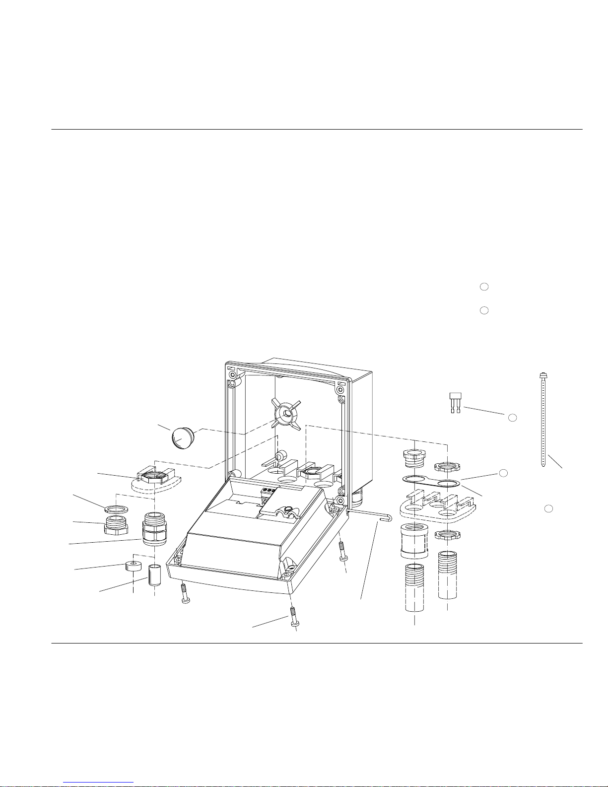
Package Contents and Unpacking
Unpack the unit carefully and check the shipment for
transport damage and completeness.
The package contains:
–Front unit of Transmitter
–Lower case
–Short instruction sheet
–This instruction manual
–HART description
(only for Model APT2000TC-H-..)
–Bag containing:
➀ 2 plastic plugs ➆ 1 hinge pin
➁ 5 hexagon nuts ➇ 3 cable ties
➂ 3 Pg cable glands ➈ 3 filler plugs
➃ 1 rubber reducer ➉ 3 sealing rings
➄ 1 Pg plug
11 1 metal plate
➅ 4 set screws for conduit
12
1 jumper
Assembly
Fig. 1 Assembling the case
➀
(For sealing in case
of wall mounting)
➁
➂
➃
➄
➅
➆
(Can be inserted
from either side)
➇
➈
➉
11
For conduit mounting:
Place washer
between enclosure
and nut.
11
12
Page 7
Assembly
7
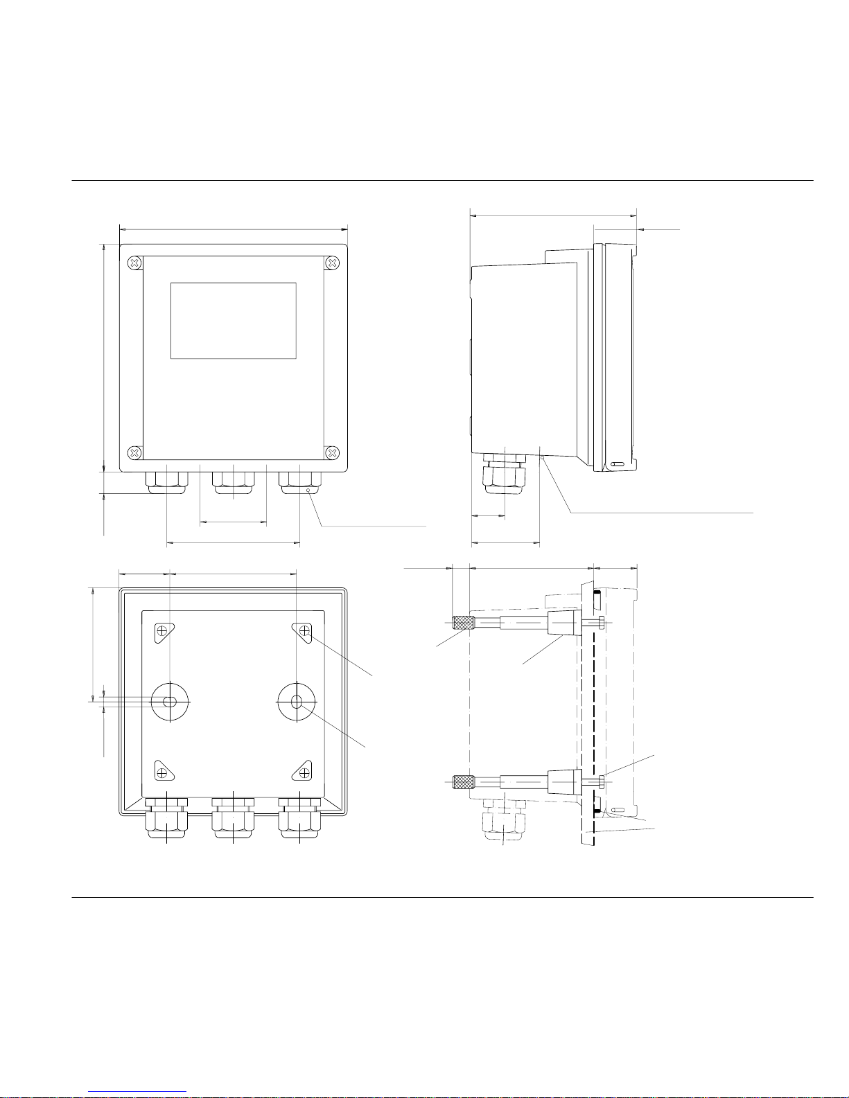
80 [3.15]
32 [1.26]
72 [2.83]
6.2 [0.24]
approx. 14
84 [3.31]
42 [1.65]
Pg 13.5 (3 pcs.)
144 [5.67]
144 [5.67]
21
43 [1.69]
105 [4.13]
27
Control panel 1 – 22 mm
max. 25
78 [3.07]
27
Control panel cutout
138 x 138 mm (DIN 43700)
Panel-mount kit
consisting of:
4 screws
4 span pieces
4 threaded sleeves
1 seal
➀
➁
➂
➃
➃
➀
➁
➂
Holes for
post mounting
Holes for
wall mounting
(4 x)
(2 x)
[0.55]
[1.06]
[0.83]
[0.98]
[1.06]
[5.43 x 5.43]
[0.04 – 0.87]
Note: All dimensions
in mm [inches]
(not included in supply)
2 holes 21.5 mm dia. [8.47] for Pg 13.5
I
or 1/2 conduit
Fig. 2 Dimension drawing for Transmitter, mounting diagram and P/N 51205990-001 panel-mount kit
Page 8
Assembly
8
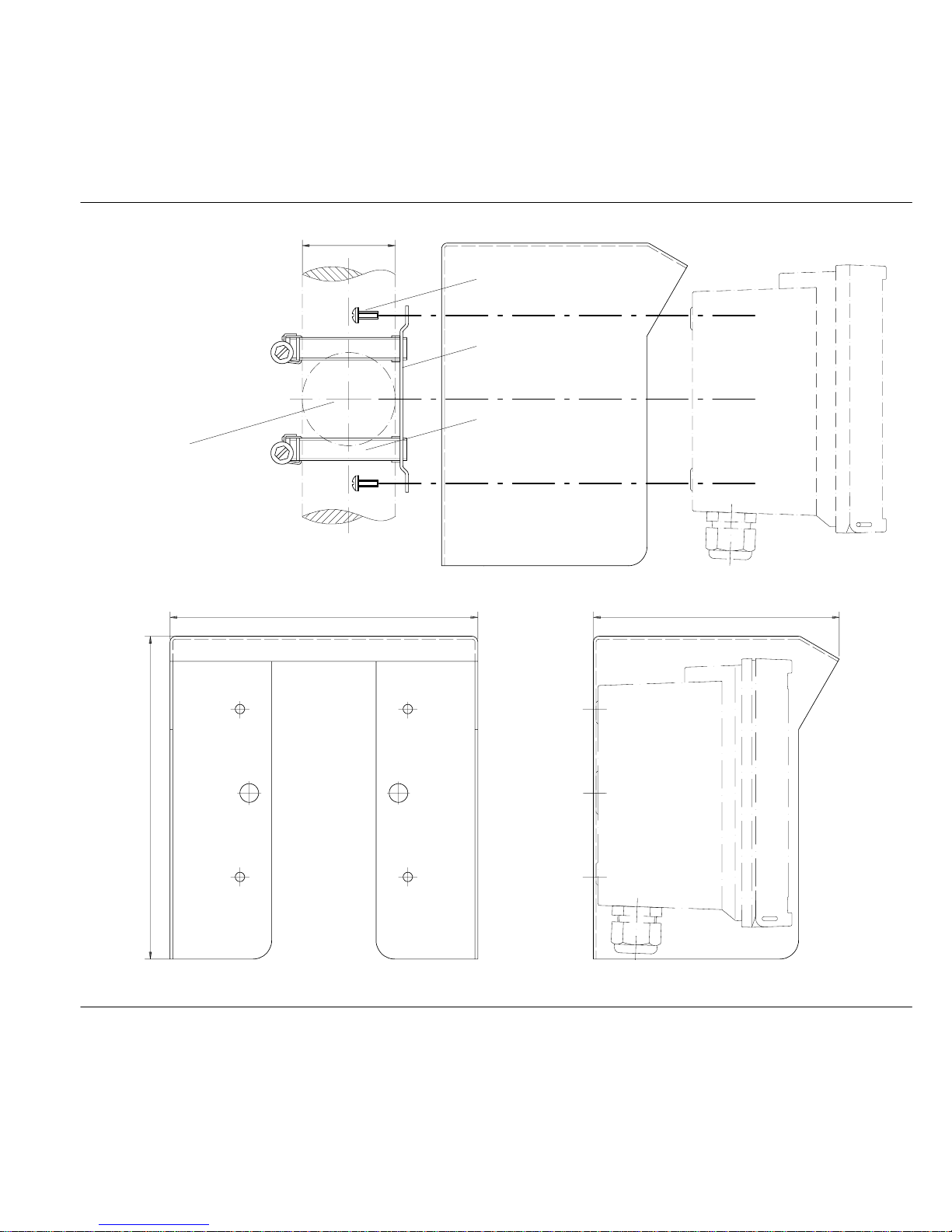
horizontal post/
40–60 mm dia.
➀
➁
➂
51205989-001
(if required)
For vertical or
pipe mounting
Pipe-mount kit
consisting of:
4 self-tapping screws
1 pipe mounting plate
2 hose clamps with
➀
➁
➂
worm gear drive
to DIN 3017
[1.57–2.36]
protective hood
Fig. 3 P/N 51205988-001 pipe-mount kit
165 [6.5]
173 [6.81]
132 [5.2]
Fig. 4 P/N 51205989-001 protective hood for wall and pipe mounting
Page 9
Assembly
9
280 [11.03]
7 [0.28]
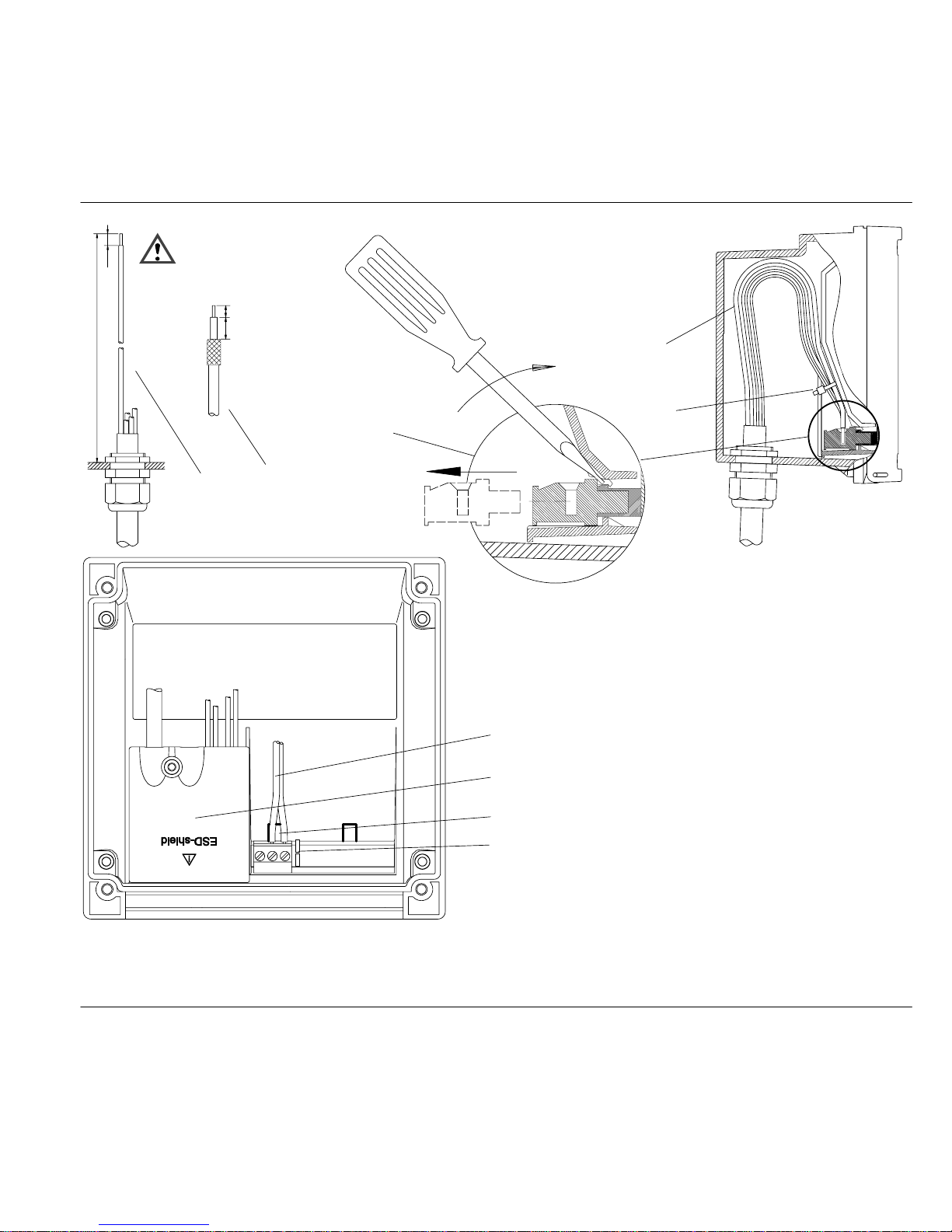
➀ Recommended stripping lengths for
multi-core cables
➁ Recommended stripping length for
coaxial cable
➂ Pulling out the terminals using a
screwdriver (also see
➆)
➃
Cable laying in the Transmitter
➄ Connecting lines for loop current
➅ Cover for sensor and temperature
probe terminals
➆ Areas for placing the screwdriver to
pull out the terminals
➇ Connection of handheld terminal
➀
➁
➃
➄
Be sure not to
notch the cable
cores when stripping
the insulation!
Dimensions in mm [inches].
➄
➅
➆
➇
Coaxial cable
13 mm [0.5]
7 mm [0.28]
➂
Fig. 5 Installation information
Page 10
Warning
Warning
Warning
Capabilities, Connection
10
2 Installation, Connection and Commissioning
Proper Use
The APT2000TC Transmitter is used for conductivity
and temperature measurement in chemical, pulp and
paper , biotechnology, food processing, pharmaceutical, electroplating, and water/wastewater industries.
It can either be mounted on site or in a control panel.
The APT2000TC-0(H)-00
Transmitter is approved for operation in safe areas and hazardous
locations DIV 2 (USA/Canada only).
Before connecting the Transmitter
to a power supply unit, make sure
that this is not capable of outputting
more than 40 Vdc (safe areas) /
30 Vdc (DIV 2).
The APT2000TC-0(H)-IS Transmitter is approved for operation in hazardous locations DIV 1 (USA/Canada) / Zone 1 (Europe).
Before connecting the Transmitter
to a power supply unit, make sure
that this is an associated apparatus.
The measuring inputs of the APT
2000PH-0(H)-IS Transmitter may
be led into Zone 0 (Europe).
However, be sure to observe the
national regulations concerning
Zone 0 applications.
The Transmitter itself is not approved for operation in Zone 0!
Page 11
Capabilities, Connection
11
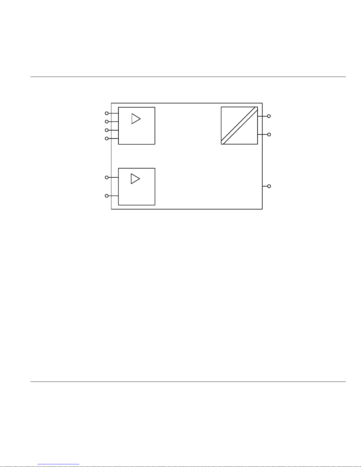
Overview of the Conductivity Transmitter
mS/cm,
% by wt, SAL
Temperature
Pt 100/1000/
NTC 100 kW
mA
APT2000TC Transmitter
➀
➁
➃
➂
Fig. 6 System functions of APT2000TC Transmitter
➀ Inputs for toroidal conductivity sensors
➁ Input for temperature probe
➂ Current loop 4 – 20 mA,
transports power to and output signal from the
transmitter,
with APT2000TC-H-.. Transmitter also for HARTr
communication
➃ Equipotential bonding (only with
APT2000TC-0(H)-IS Transmitter)
Page 12
Capabilities, Connection
12
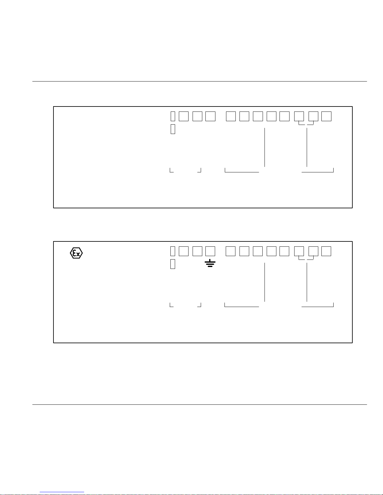
Terminal Assignment
8 7 6 5 4 2 1
3
T1
temp
n.c.
+ 11 10
4 to
+
9
output
–
HART
20 mA
supply/
do not
connect
toroidal
conductivity sensor
lo hilohi
send receive
WT
BL
YW
GN
shield
RD
–
Fig. 7 Terminal assignment of APT2000TC-0(H)-00 Transmitter
NI, Class 1, Div 2, Group A – D, T4
8 7 6 5 4 2 1
3
T1
temp
n.c.
+ 11 10
4 to
+
9
output
–
HART
20 mA
supply/ toroidal
conductivity sensor
lo hilohi
send receive
WT
BL
YW
GN
shield
RD
–
Fig. 8 Terminal assignment of APT2000TC-0(H)-IS T ransmitter
IS, Class I, Div 1, Group A – D, T4
II 2(1) G EEx ib [ia] IIC T6
Page 13
Warning
Warning
Warning
Warning
Warning
Capabilities, Connection
13
Installation and Commissioning
Installation and commissioning of
the Transmitter may only be carried
out in accordance with this instruction manual and per applicable local
and national codes. Be sure to observe the technical specifications
and input ratings.
Before connecting the
APT2000TC-0(H)-00 Transmitter to
a power supply unit, make sure that
this is not capable of outputting
more than 40 Vdc (safe areas) /
30 Vdc (DIV 2).
Before connecting the
APT2000TC-0(H)-IS Transmitter
to a power supply unit, make sure
that this is an associated apparatus
(for input ratings refer to the Control
Drawing or the annex of the EC
Type Examination Certificate).
Do not use alternating current or
mains power supply!
When commissioning, a complete
configuration must be carried out.
For easier installation, the terminal strips are of a
plug-in design. The terminals are suitable for single
wires and flexible leads up to 2.5 mm
2
(AWG 14)
(see Pg. 9).
A connection example is shown on Pg. 14.
Page 14
Warning
Note
Capabilities, Connection
14
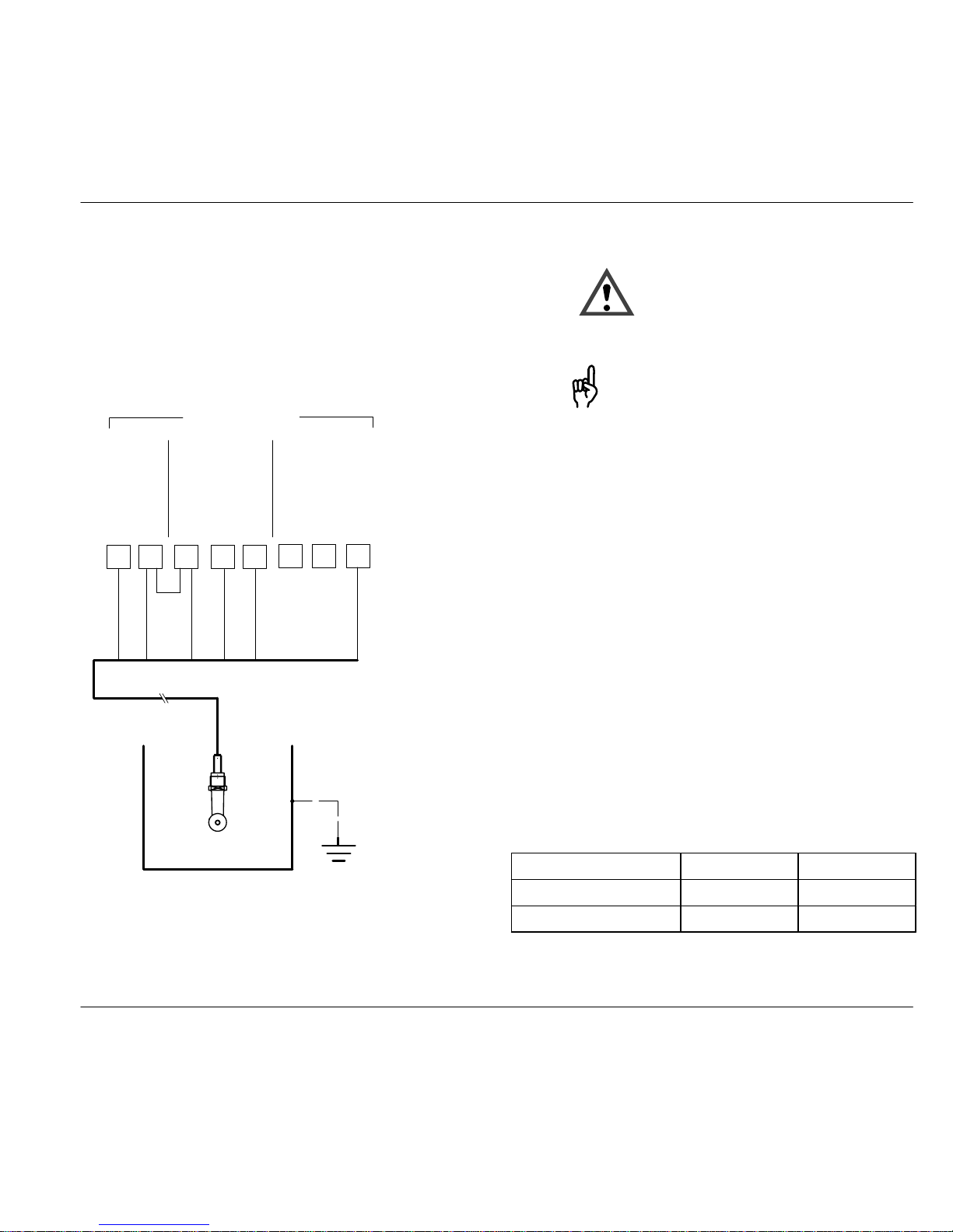
Typical Wiring
Conductivity measurement with Honeywell
5000TC toroidal conductivity sensor
The Honeywell 5000TC toroidal conductivity sensor
is used to measure low to highest conductivity values. It can be used for measurements in safe areas.
WHITE
BLUE
YELLOW
GREEN
RED
SHIELD
toroidal
cond. sensor
5421
3
temp
lohi lo hi
sendreceive
WT
BL
YW
GN
shield
RD
87
6
T1
T2
n.c.
Fig. 9 Conductivity measurement with Honeywell
5000TC toroidal conductivity sensor
The Honeywell 5000TC toroidal
conductivity sensor may only be
used in combination with the
APT2000TC-0(H)-00 Transmitter.
For special mounting conditions of
the sensor, the cell factor can vary
between 4.0 and 4.5. Therefore the
user should perform a wet calibration of each new sensor to determine the exact cell factor.
Settings for Honeywell 5000TC toroidal conductivity
sensor
Menu Setting
Temp probe conf 1200 Pt 1000
Cell factor cal 1100 4.44
Page 15
Operation
15
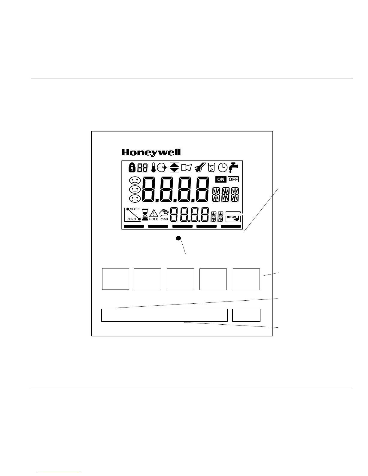
3 Operation
User Interface
MEAS
Alarm LED
Keypad
Model designation
Rating plate
Status fields:
- Measuring mode
- Calibration mode
- Alarm
- Configuration mode
CAL ALARM CONF
CONF ENTER
CAL
"
"
Fig. 10 Front view of Transmitter
Page 16

CAL
CONF
"
Y
ENTER
➔
CAL
ENTER
➔
CONF
ENTER
+
Y
"
Operation
16
Display
Mode code entry
Interval/
Response time
Hold state
active
Continue with
ENTER
Measurement symbols
Tempera-
ture
Loop
current
Alarm
setting
Sensocheck
Calibration
Sensor
data
Sensoface
Wait
Display/
Process variable
Bar for
instrument status
Fig. 11 Display of Transmitter
Keypad
Start, end calibration
Start, end configuration
Select digit position
(selected position flashes)
Change digit
Prompt in display:
continue in program sequence,
Configuration:
Confirm entries, next
configuration step,
Measuring mode:
Display loop cur-
rent
Cal info, display cell factor and zero
point (see Pg. 25)
Error info, display last output error
message (see Pg. 25)
Start GainCheck
manual instru-
ment self-test (see Pg. 17)
Page 17

+
Y
"
Operation
17
Safety Functions
Sensoface sensor monitoring
Sensoface
provides information
on the sensor condition. A sad
“Smiley” indicates that there is a
Sensocheck
message.
Sensocheck
signals a short circuit of the primary coil and its lines
as well as an interruption at the
secondary coil and its lines. Sensocheck
can be switched off. With
Sensocheck
switched off, no
friendly Smiley appears.
For more detailed information, see chapter “Diagnostic, Maintenance and Cleaning” (Pg. 26).
GainCheck
manual instrument self-test
Simultaneously pressing Y and "
starts the manual instrument selftest.
A display test is carried out, the software version is
displayed and the memory and measured value
transmission are checked.
Automatic instrument self-test
The automatic unit self-test checks the memory and
the measured-value transmission. It runs automatically in the background at fixed intervals.
Page 18

Operation
18
Outputs
Current loop (4 to 20 mA)
The current loop transports power to and output signals from the Transmitter. The current is controlled
by the process variable selected in the configuration.
The current characteristic can be configured as linear or logarithmic curve for conductivity and resistivity.
The current beginning and end can be set to represent any desired value.
If LIN (linear characteristic) is chosen, the minimum
span is 5% of the selected process variable / measurement range. If LOG (logarithmic characteristic) is
chosen, the minimum span is one decade within the
chosen range.
To check connected peripherals (e.g. limit switches,
controllers), the loop current can be manually specified (see Pg. 28).
HART
communication
The APT2000TC-H-.. Transmitter can be remote
controlled via HART
communication. It can be configured using a handheld terminal or from the control
room. Measured values, messages and instrument
identification can be downloaded at any time. This
allows easy integration also in fully automatic process sequences.
For more detailed information, refer to the HART
Command Specification.
Alarm
During an error message the alarm LED flashes.
Alarm response time is permanently set to 10 sec.
Error messages can also be signaled with a 22 mA
signal via the loop current (see Configuration,
Pg. 20).
Page 19

CONF
Note
Operation
19
Configuration
The instrument arrives from the factory configured
and ready to operate as a conductivity transmitter.
This section provides detailed procedures for changing operation values for specific applications.
Activate with CONF
change parameter with Y and ",
confirm/continue with ENTER,
end with CONF.
Mode code “1200”
During configuration the Transmitter
is in the Hold state, the loop current
is frozen.
When the configuration mode is exited, the Transmitter remains in the Hold state for safety reasons. This
prevents undesirable reactions of the connected peripherals (e.g. limit switches, controllers) due to incorrect settings. The measured value and Hold are
displayed alternately. Now you can check whether
the measured value is plausible and specifically end
the Hold state with ENTER. After a relax time of
20 sec (for measured value stabilization) the Transmitter returns to measuring mode.
The configuration parameters are
checked during the input. In the
case of an incorrect input “ERR” is
displayed for 3 sec. The parameters cannot be stored with ENTER
until the input has been repeated.
Configuration parameters
Before attempting any changes refer to the parameter setup list shown below. This table presents the possible options and the factory settings.
Pictograph
Parameter Choices Factory
setting
Process variable / meas. range
Selected process variable and
measuring range control loop cur-
rent, limit values and display.
Complete configuration required
after change.
oo.oo mS / ooo.o mS / oooo mS
ooo.o %
ooo.o SAL
ooo.o mS
Concentration
(only with %)
-01- NaCl (0 – 28 % by wt)
-02- HCl (0 – 17 % by wt)
-03- NaOH (0 – 22 % by wt)
-04- H2SO4(0 – 35 % by wt)
-05- HNO
3
(0 – 28 % by wt)
-06- H
2SO4
(95 – 99 % by wt)
-01-
Temperature display °C
°F
°C
Page 20

Operation
20
Temperature probe Pt 100 / Pt 1000 /
NTC 100 kW
Pt 1000
T emperature compensation
(not with % and SAL)
OFF
LIN
NLF (natural waters)
OFF
Temperature coefficient
(only with tc LIN)
xx.xx %/K 02.00 %/K
Current characteristic
(not with % and SAL)
LIN
LOG
LIN
Current beginning (4 mA)
(only with LIN)
mS / % / SAL 000.0 mS
Current end (20 mA)
(only with LIN)
mS / % / SAL
100.0 mS
Current beginning (4 mA)
(only with LOG)
mS *
0.1 mS
Current end (20 mA)
(only with LOG)
mS *
100 mS
Hold state Last:Last current value
Fix: Current specified
Last
Hold value
(only with Fix)
xx.xx mA 21.00 mA
22 mA signal for error message ON / OFF OFF
Sensocheck
ON / OFF OFF
* 0.1 / 1 / 10 / 100 / 1000 mS
Configuration is cyclical. To stop, press CONF.
Page 21

CAL
CAL
ENTER
Operation
21
Calibration
In the calibration mode the cell factor can be modified in two ways. If the cell factor of the sensor in use
is known under consideration of the installation conditions, it can be entered directly. Furthermore, the
cell factor can be determined with a known calibration solution under consideration of the temperature.
Activate with CAL,
confirm/continue with ENTER,
abort with CAL ➜ ENTER
During calibration the Transmitter is
in the Hold state. The loop current
is frozen.
When the calibration mode is exited, the Transmitter
remains in the Hold state for safety reasons. This
prevents undesirable reactions of the connected peripherals (e.g. limit switches, controllers) due to incorrect settings. The measured value and Hold are
displayed alternately. Now you can check whether
the measured value is plausible and specifically end
the Hold state with ENTER or repeat calibration with
CAL. When you end the Hold state, the Transmitter
will return to measuring mode after 20 sec (measured value stabilization).
Calibration by input of cell factor
Activate calibration by pressing the
CAL key.
Using the Y , " keys enter
mode code “1100” and then press
ENTER.
Using the Y , " keys enter the cell
factor. The lower display shows the
conductivity value.
A change in the cell factor also
changes the conductivity value.
When there has not been an entry
for approx. 6 sec, conductivity and
temperature are displayed alternately.
Press ENTER to confirm the cell
factor.
The Transmitter remains in the Hold
state. You can end the Hold state
with ENTER. After 20 sec (measured value stabilization) the Transmitter returns to measuring mode.
Page 22

Note
CAL
ENTER
Operation
22
Calibration with calibration solution
Be sure to use known calibration
solutions and the respective temperature-corrected table values (see
Calibration Solutions, Pg. 38).
Activate calibration by pressing the
CAL key.
Using the Y , " keys enter
mode code “1100” and then press
ENTER.
Immerse the sensor in the calibration solution.
After approx. 6 sec the lower display alternately shows the conductivity and temperature values. Read
the conductivity value corresponding to the displayed temperature
from the table of the used calibration solution (for tables see Pg. 38).
Using the Y , " keys change the
cell factor until the display shows
the conductivity value from the
table.
Make sure that the temperature is
stable during the calibration procedure.
Press ENTER to confirm the cell
factor.
The Transmitter remains in the Hold
state. You can end the Hold state
with ENTER. After 20 sec (measured value stabilization) the Transmitter returns to measuring mode.
Page 23

Note
Note
CAL
ENTER
Note
Note
CAL
Operation
23
Zero point calibration in air
Zero point calibration is only required when very low conductivity
values are to be measured.
Before you start calibration, remove
the sensor from the process, clean
it and dry it up.
Activate calibration by pressing the
CAL key.
Using the Y , " keys enter
mode code “1001” and then press
ENTER.
Using the Y , " keys modify the
zero point until the lower display
reads 0 mS. If required, change the
sign of the zero point!
When there has not been an entry
for approx. 6 sec, the lower display
alternately shows the zero-corrected conductivity value and the
temperature value.
Press ENTER to confirm the zero
point.
The Transmitter remains in the Hold
state. You can end the Hold state
with ENTER. After 20 sec (measured value stabilization) the Transmitter returns to measuring mode.
Input and adjustment of sensor factor
This function should only be used
by experts. Incorrectly set parameters may go unnoticed, but change
the measuring properties.
The Transmitter comes with a preset sensor factor of
24.6 for the 5000TC sensor. Should you use another
sensor , you must enter another sensor factor or determine it using a comparison resistor. After that, you
can calibrate the sensor (see Pg. 21).
Resistance measurement in test
mode can only show the correct
value of the test resistor when the
sensor factor has been correctly
determined.
Activate calibration by pressing the
CAL key.
Using the Y , " keys enter
mode code “1125” and then press
ENTER.
Using the Y , " keys enter the
sensor factor of the sensor in the
main display .
If you do not know the sensor factor, it can be determined using a
comparison resistor (recommended
resistance value: 100 W). The sensor factor must be adjusted until the
corresponding resistance value is
shown in the lower display.
Page 24

ENTER
Note
CAL
ENTER
Operation
24
Press ENTER to confirm the sensor factor.
The Transmitter remains in the Hold
state. You can end the Hold state
with ENTER. After 20 sec (measured value stabilization) the Transmitter returns to measuring mode.
Adjustment of temperature probe
This function should only be used
by experts. Incorrectly set parameters may go unnoticed, but change
the measuring properties.
Especially for Pt 100 temperature
probe, it is advisable to perform an
adjustment.
Activate calibration by pressing the
CAL key.
Using the Y , " keys enter
mode code “1015” and then press
ENTER.
Measure the temperature of the
process medium using an external
thermometer.
Using the Y , " keys enter the determined temperature value in the
main display. If you take over the
temperature value shown in the
lower display, the correction is without effect.
Press ENTER to confirm the temperature value.
The Transmitter remains in the Hold
state. You can end the Hold state
with ENTER. After a relax time of
20 sec (for measured value stabilization) the Transmitter returns to
measuring mode.
Page 25

Note
Operation
25
Measurement
Measuring mode
In the measuring mode the main display shows the
configured process variable and the lower display
the temperature.
Cal info
With CAL and mode code “0000” you can activate
the cal info. Cal info shows the current calibration
data for approx. 20 sec. The 20 sec can be reduced
by pressing ENTER. During cal info the Transmitter
is not
in Hold state.
Error info
With CONF and mode code “0000” you can activate
the error info. Error info shows the most recent error
message for approx. 20 sec. After that the message
will be deleted. The 20 sec can be reduced by pressing ENTER. During error info the Transmitter is not
in Hold state.
Hold state
The Transmitter will enter the Hold state under the
following conditions:
For calibration: Mode code 1001
Mode code 1015
Mode code 1100
Mode code 1125
Mode code 2222
configuration: Mode code 1200
Mode code 5555
The loop current is frozen at Last or Fix (configuration Pg. 20).
If the calibration or configuration mode is exited, the
Transmitter remains in the Hold state for safety reasons. This prevents undesirable reactions of the connected peripherals (e.g. limit switches, controllers)
due to incorrect settings. The measured value and
Hold are displayed alternately. Now you can check
whether the measured value is plausible and specifically end the Hold state with ENTER. After a relax
time of 20 sec (for measured value stabilization) the
Transmitter returns to measuring mode.
During error conditions the Hold
state will not be active.
Page 26

CONF
ENTER
Troubleshooting, Cleaning
26
4 Diagnostics, Maintenance and Cleaning
Sensoface, Sensocheck
Sensoface provides information
on the sensor condition. A sad
“Smiley” indicates that there is a
Sensocheck
message.
Sensocheck
signals a short circuit of the primary
coil and its lines as well as an interruption at the secondary coil and its lines. Sensocheck
can be
switched off. With Sensocheck
switched off, no
friendly Smiley appears.
Error Messages
When one of the following error messages is output,
the Transmitter can no longer correctly determine the
process variable or output it via the loop current.
During an error message the alarm LED flashes. The
alarm response time is permanently set to 10 sec.
Error messages can also be signaled with a 22 mA
signal via the loop current (see Configuration,
Pg. 20).
Error info
With CONF and mode code “0000”
you can activate the error info.
Error info shows the most recent
error message for approx. 20 sec.
After that the message will be deleted. The 20 sec can be reduced by
pressing ENTER. During error info
the Transmitter is not
in Hold state.
Error
number
Display
(flashing)
Problem Possible causes
Err 01 Sensor - Wrong cell factor
- Outside measurement range
- SAL > 45 ‰
- Sensor connection or cable defective
Err 02 Sensor - Unsuitable sensor
Err 03 Temperature probe - Outside temp range
- Outside temp range for TC
- Outside temp range for SAL
- Outside temp range for concentration
Err 21 Loop current - Meas. value below configured current beginning
- Wrong configuration for current beginning (see Pg. 20)
Page 27

Troubleshooting, Cleaning
27
Error
number
Possible causesProblemDisplay
(flashing)
Err 22 Loop current - Meas. value above configured current end
- Wrong configuration for current end (see Pg. 20)
Err 23 Loop current - Configured current span too small
(Difference between current beginning and end)
Err 33 Sensocheck
- Short circuit in primary coil
- Short circuit of cable
Err 34 Sensocheck
- Open circuit in secondary coil
- Cable interrupted
Err 98 System error - Configuration or calibration data defective; completely
reconfigure and recalibrate the Transmitter
- Measured value transmission defective
- Memory error in Transmitter program (PROM defective)
Err 99 Factory settings - EEPROM or RAM defective
- Error in factory settings
This error message normally should not occur, as the
data are protected from loss by multiple safety functions.
Should this error message nevertheless occur, there is
no remedy. The Transmitter must be repaired and recalibrated at the factory.
Page 28

Warning
Troubleshooting, Cleaning
28
Diagnostics Functions
Cal info
Pressing CAL and entering mode code “0000” is
going to activate the cal info. Cal info shows the current calibration data for approx. 20 sec. During cal
info the Transmitter is not
in Hold state.
Test mode
Pressing CAL and entering mode code “2222” is
going to activate the test mode. In the test mode you
can check the measuring equipment with a resistor.
Sensoface
is disabled.
To do so, a comparison resistor is
looped through the sensor. The
comparison resistance value is indicated in the main display in kW.
When the resistance value exceeds
2 kW, the display shows “– – – –”.
R: e.g. 100 W
Pressing ENTER ends the test mode. The T ransmitter goes to Hold state.
Error info
Pressing CONF and entering mode code “0000” is
going to activate the error info. Error info shows the
most recent error message for approx. 20 sec. After
that the message will be deleted. During error info
the Transmitter is not
in Hold state.
Display loop current
Pressing ENTER in measuring mode displays the
loop current for a few seconds.
Current source
To check the connected peripherals (e.g. limit
switches, controllers), the loop current can be manually specified.
In the current source mode the loop
current no longer follows the measured value! It is manually specified.
Therefore, it must be ensured that
the connected devices (control
room, controllers, indicators) do not
interpret the current value as a
measured value!
Pressing CONF and entering mode code “5555” is
going to activate the current source mode. Specify
the loop current using ", Y and ENTER. The actually flowing loop current is shown in the lower display.
Pressing CONF exits the current source mode
again.
GainCheck
manual instrument self-test
The manual instrument self-test is started by simultaneously pressing Y and ".
A display test is carried out, the software version is
displayed and the memory and measured-value
transmission are checked.
Page 29

Troubleshooting, Cleaning
29
Automatic self-test
The automatic self-test checks the memory and the
measured-value transmission. It runs automatically
in the background at fixed intervals.
Maintenance and Cleaning
Maintenance
The Transmitter contains no user repairable components. If problems persist even after reviewing section 4, please contact the factory.
Cleaning
To remove dust, dirt and spots, the external surfaces
of the Transmitter may be wiped with a damp, lintfree cloth. A mild household cleaner may also be
used if necessary .
Page 30

Specifications
30
5 Appendix
Product Line
Units
Ref. No.
Toroidal Conductivity Transmitter for application in safe
areas or hazardous locations
DIV 2 (USA/Canada only)
APT2000TC-0-00
Toroidal Conductivity IS
Transmitter for application in
hazardous locations
DIV 1 (USA/Canada) / Zone 1
(Europe)
APT2000TC-0-IS
Toroidal Conductivity Transmitter with HART
communication for application in safe
areas or hazardous locations
DIV 2 (USA/Canada only)
APT2000TC-H-00
Toroidal Conductivity IS
Transmitter with HART
communication, for application in
hazardous locations
DIV 1 (USA/Canada) / Zone 1
(Europe)
APT2000TC-H-IS
Mounting Accessories
Ref. No.
Pipe-mount kit 51205988-001
Panel-mount kit 51205990-001
Protective hood 51205989-001
Further Accessories
Ref. No.
HART
test socket, integrated in
Pg cable gland
(for APT2000TC-H-.. Transmitter
only)
51205991-001
Page 31

Specifications
31
Specifications
APT2000TC-0(H)-00 Transmitter
Cond input
Input for Series 5000 toroidal conductivity sensor
Process variable/ranges**
00.00 to 99.99 mS/cm
000.0 to 999.9 mS/cm
0000 to 9999 mS/cm
Concentration0.0 to 100.0 % by wt.
Salinity
0.0 to 45.0 ‰ (0 to 35 °C)
Accuracy***
< 1 % of meas. value ± 0.02 mS/cm
Sensor
monitoring
Sensocheck: monitoring of primary
and lines for short circuit and monitor-
ing of secondary for open circuit
(can be switched off)
Sensor standardization
*
– Entry of cell factor with display
of conductivity and temperature
– Zero point adjustment
– Temperature probe adjustment
– Input of sensor factor
Permissible
cell factor
0.100 to 19.999
Permissible
sensor factor
1.00 to 99.99
Permissible
offset
± 0.5 mS/cm
APT2000TC-0(H)-IS Transmitter
Cond input
Input for Series 5000 toroidal conductivity sensor
Process variable/ranges**
00.00 to 99.99 mS/cm
000.0 to 999.9 mS/cm
0000 to 9999 mS/cm
Concentration0.0 to 100.0 % by wt.
Salinity
0.0 to 45.0 ‰ (0 to 35 °C)
Accuracy***
< 1 % of meas. value ± 0.02 mS/cm
Sensor
monitoring
Sensocheck: monitoring of primary
and lines for short circuit and monitor-
ing of secondary for open circuit
(can be switched off)
Sensor standardization
*
– Entry of cell factor with display
of conductivity and temperature
– Zero point adjustment
– Temperature probe adjustment
– Input of sensor factor
Permissible
cell factor
0.100 to 19.999
Permissible
sensor factor
1.00 to 99.99
Permissible
offset
± 0.5 mS/cm
Page 32

Specifications
32
APT2000TC-0(H)-00 Transmitter
Temp input
Pt 100 / Pt 1000 / NTC 100 kW
Ranges
– NTC –10.0 to +130.0 °C
+14 to +266 °F
– Pt –20.0 to +150.0 °C
–4 to +302 °F
Resolution 0.1 °C / 1 °F
Accuracy < 0.5 K****
Temp com-
pensation
*
(Ref. temp
25 °C)
LIN 00.00 to 19.99 %/K
NLF Natural waters to
EN 27888 (0 to 36 °C)
Concentration determination
-01- NaCl 0-26.3 % by wt (0 °C) ...
0-28.1 % by wt (100 °C)
-02- HCl 0-17 % by wt (-20 °C) ...
0-17 % by wt (50 °C)
-03- NaOH 0-12 % by wt (0 °C) ...
0-22 % by wt (100 °C)
-04- H
2SO4
0-25 % by wt (-17 °C) ...
0-35 % by wt (110 °C)
-05- HNO
3
0-28 % by wt (-20 °C) ...
0-28 % by wt (50 °C)
-06- H
2SO4
95-99 % by wt (-10 °C) ...
95-99 % by wt (110 °C)
Display LC display, alarm LED
Loop current 4 to 20 mA, floating
22 mA for error message
*
supply voltage 14 to 40 V
Characteristic
*
Linear or logarithmic
Current error
< 0.3 % of current value ± 0.05 mA
APT2000TC-0(H)-IS Transmitter
Temp input
Pt 100 / Pt 1000 / NTC 100 kW
Ranges
– NTC –10.0 to +130.0 °C
+14 to +266 °F
– Pt –20.0 to +150.0 °C
–4 to +302 °F
Resolution 0.1 °C / 1 °F
Accuracy < 0.5 K****
Temp com-
pensation
*
(Ref. temp
25 °C)
LIN 00.00 to 19.99 %/K
NLF Natural waters to
EN 27888 (0 to 36 °C)
Concentration determination
-01- NaCl 0-26.3 % by wt (0 °C) ...
0-28.1 % by wt (100 °C)
-02- HCl 0-17 % by wt (-20 °C) ...
0-17 % by wt (50 °C)
-03- NaOH 0-12 % by wt (0 °C) ...
0-22 % by wt (100 °C)
-04- H
2SO4
0-25 % by wt (-17 °C) ...
0-35 % by wt (110 °C)
-05- HNO
3
0-28 % by wt (-20 °C) ...
0-28 % by wt (50 °C)
-06- H
2SO4
95-99 % by wt (-10 °C) ...
95-99 % by wt (110 °C)
Display LC display , alarm LED
Loop current
EEx ib IIC
4 to 20 mA, floating
22 mA for error message
*
supply voltage 14 to 30 V,
I
max
= 100 mA, P
max
= 0.8 W
Characteristic
*
Linear or logarithmic
Current error
< 0.3 % of current value ± 0.05 mA
Page 33

Specifications
33
APT2000TC-0(H)-00 Transmitter
Start/End of
scale
*
As desired within ranges for
mS, %, SAL
Min. span LIN 5 % of selected range
LOG 1 decade
Current
source
3.8 mA to 22.00 mA
HART
com-
munication
(HART transmitter only)
Digital communication via FSK modulation of loop current, reading of device identification, measured values,
status and messages
reading and writing of parameters
Explosion
protection
USA/Canada:
NI, Class I, Div 2, Group A – D, T4
Data
retention
> 10 years (EEPROM)
RFI suppression
To EN 50081-1 and EN 50081-2
Immunity to
interference
To EN 50082-1 and EN 50082-2
Temperature Operating/ambient temp
–20 to +55 °C
Transport and storage temp
–20 to +70 °C
Enclosure Material: thermoplastic polyester, re-
inforced (polybutylene terephthalate)
Protection: IP 65
Color: bluish gray RAL 7031
Cable glands 3 breakthroughs for Pg 13.5
2 breakthroughs for NPT 1/2 “ or
Rigid Metallic Conduit
APT2000TC-0(H)-IS Transmitter
Start/End of
scale
*
As desired within ranges for
mS, %, SAL
Min. span LIN 5 % of selected range
LOG 1 decade
Current
source
3.8 mA to 22.00 mA
HART
com-
munication
(HART transmitter only)
Digital communication via FSK modulation of loop current, reading of device identification, measured values,
status and messages
reading and writing of parameters
Explosion
protection
USA/Canada:
IS, Class I, Div 1, Group A – D, T4
Europe:
II 2G EEx ib [ia] IIC T6
CE 0032 TÜV 99 ATEX 1430
Data
retention
> 10 years (EEPROM)
RFI suppression
To EN 50081-1 and EN 50081-2
Immunity to
interference
To EN 50082-1 and EN 50082-2
Temperature Operating/ambient temp
–20 to +55 °C
Transport and storage temp
–20 to +70 °C
Enclosure Material: thermoplastic polyester, re-
inforced (polybutylene terephthalate)
Protection: IP 65
Color: bluish gray RAL 7031
Cable glands 3 breakthroughs for Pg 13.5
2 breakthroughs for NPT 1/2 “ or
Rigid Metallic Conduit
Page 34

Specifications
34
APT2000TC-0(H)-00 Transmitter
Dimensions
See Dimension drawings, Pg. 7 ff
Weight approx. 1 kg
* user defined
** displayed with 3 1/2 digits
*** ± 1 count
**** with Pt 100 < 1K, with NTC > 100 °C < 1 K
APT2000TC-0(H)-IS Transmitter
Dimensions
See Dimension drawings, Pg. 7 ff
Weight approx. 1 kg
* user defined
** displayed with 3 1/2 digits
*** ± 1 count
**** with Pt 100 < 1K, with NTC > 100 °C < 1 K
Page 35

Certificate of Conformity
35
Type Examination Certificate
Page 36

Certificate of Conformity
36
Page 37

Certificate of Conformity
37
Page 38

Calibration Solutions
38
Calibration Solutions
Potassium Chloride Solutions
Electrical Conductivity in mS/cm
Temperature
[°C]
Concentration
0.01 mol/l 0.1 mol/l 1 mol/l
0
0.776 7.15 65.41
5 0.896 8.22 74.14
10 1.020 9.33 83.19
15 1.147 10.48 92.52
16 1.173 10.72 94.41
17 1.199 10.95 96.31
18 1.225 11.19 98.22
19 1.251 11.43 100.14
20 1.278 11.67 102.07
21 1.305 11.91 104.00
22 1.332 12.15 105.94
23 1.359 12.39 107.89
24 1.386 12.64 109.84
25 1.413 12.88 111.80
26 1.441 13.13 113.77
27 1.468 13.37 115.74
28 1.496 13.62
29 1.524 13.87
30 1.552 14.12
31 1.581 14.37
32 1.609 14.62
33 1.638 14.88
34 1.667 15.13
35 1.696 15.39
36
15.64
Data source: K. H. Hellwege (Editor), H. Landolt, R. Börnstein: Zahlen-
werte und Funktionen .... Volume 2, Part. Volume 6
Data source: * K. H. Hellwege (Editor), H. Landolt, R. Börnstein: Zahlen-
werte und Funktionen .... Volume 2, Part. Volume 6
** Test solutions calculated according to IEC 746-3
Sodium Chloride Solutions
Electrical Conductivity in mS/cm
Temperature
[°C]
Concentration
saturated* 0.1 mol/l** 0.01 mol/l**
0
134.5 5.786 0.631
1 138.6 5.965 0.651
2 142.7 6.145 0.671
3 146.9 6.327 0.692
4 151.2 6.510 0.712
5 155.5 6.695 0.733
6 159.9 6.881 0.754
7 164.3 7.068 0.775
8 168.8 7.257 0.796
9 173.4 7.447 0.818
10 177.9 7.638 0.839
11 182.6 7.831 0.861
12 187.2 8.025 0.883
13 191.9 8.221 0.905
14 196.7 8.418 0.927
15 201.5 8.617 0.950
16 206.3 8.816 0.972
17 211.2 9.018 0.995
18 216.1 9.221 1.018
19 221.0 9.425 1.041
20 226.0 9.631 1.064
21 231.0 9.838 1.087
22 236.1 10.047 1.111
23 241.1 10.258 1.135
24 246.2 10.469 1.159
25 251.3 10.683 1.183
26 256.5 10.898 1.207
27 261.6 11.114 1.232
28 266.9 11.332 1.256
29 272.1 11.552 1.281
30 277.4 11.773 1.306
31 282.7 11.995 1.331
32 288.0 12.220 1.357
33 293.3 12.445 1.382
34 298.7 12.673 1.408
35 304.1 12.902 1.434
36
309.5 13.132 1.460
Page 39

Concentration Curves
39
Concentration Curves
Conductivity [mS/cm]
700
600
500
400
300
200
100
0
0 5 10 15 20 25 30
Concentration [% by wt]
Concentration calculation error [% by wt]
< 0.5 < 2
100 C
°
91 C°
82 C
°
73 C°
63 C°
53 C°
46 C°
34 C°
25 C°
15 C°
10 C°
0 C°
Fig. 12 Concentration curves NaCl (configuration: concentration -01-)
Page 40

Concentration Curves
40
Conductivity [mS/cm]
1200
1000
800
600
400
200
0
024681012
Concentration [% by wt.]
Concentration calculation error [% by wt]
< 0.2 < 1 < 2
14 16 18 20
–20 C°
–10 C°
50 C°
40 C°
30 C°
25 C°
20 C°
10 C°
0 C°
Fig. 13 Concentration curves HCl (configuration: concentration -02-)
Page 41

Concentration Curves
41
Conductivity [mS/cm]
1600
1400
1200
1000
800
600
400
200
0
0
5101520
25
Concentration [% by wt]
Concentration calculation error [% by wt]
< 0.2
100 C°
90 C°
80 C°
70 C°
60 C°
50 C°
40 C°
30 C°
20 C°
10 C°
0 C°
Fig. 14 Concentration curves NaOH (configuration: concentration -03-)
Page 42

Concentration Curves
42
Conductivity [mS/cm]
1600
1400
1200
1000
800
600
400
200
0
0
5101520
25 30
Concentration [% by wt]
< 0.5
100 C°
90 C°
80 C
°
70 C
°
60 C°
50 C°
40 C°
30 C°
20 C
°
–10 C°
10 C°
0 C°
35
1800
< 1
110 C°
Concentration calculation error [% by wt]
Fig. 15 Concentration curves H2SO4 (configuration: concentration -04-)
Page 43

Concentration Curves
43
Conductivity [mS/cm]
1200
1000
800
600
400
200
0
0 5 10 15 20 25
30
Concentration [% by wt.]
< 0.2 < 1 < 2
50 C°
40 C°
30 C°
–20 C
°
–10 C
°
25 C°
20 C
°
10 C°
0 C°
Concentration calculation error [% by wt]
Fig. 16 Concentration curves HNO3 (configuration: concentration -05-)
Page 44

Concentration Curves
44
Conductivity [mS/cm]
600
400
200
0
95.0 95.5 96.0 96.5
97.5
Concentration [% by wt]
Concentration calculation error [% by wt]
< 0.2
100 C°
90 C°
80 C°
70 C°
60 C
°
50 C°
40 C°
30 C°
20 C°
–10 C
°
10 C°
0 C
°
98.0
110 C°
300
500
98.5 99.0
100
97.0
Fig. 17 Concentration curves H2SO4 (range 95 to 99 % by wt), (configuration: concentration -06-)
Page 45

Index
45
Index
, 26
22 mA signal for alarm, 18, 26
configuring, 20
A
Alarm, 18
response time, 26
Alarm LED, 26
Alarm via loop current, 18, 26
configuring, 20
Assembly, 6
C
Cal info, 25, 28
Calibration, 21
input of cell factor, 21
sensor factor adjustment, 23
temp probe adjustment, 24
with calibration solution, 22
zero point, in air, 23
Calibration data, display , 28
Calibration solutions, 38
Cell factor, calibration, 22
Cleaning, 29
Concentration curves, 39
Conductivity measurement, 25
Configuration, 19
Connecting
handheld terminal, 9
lines, 9
Connecting cable, fixing, 9
Current characteristic, configur-
ing, 20
Current loop
Hold state, 20
Hold value, 20
Current source, 28
D
Diagnostics functions, 28
Dimension drawings, 7
Display, 16
E
Error info, 25, 26, 28
Error message, last, 25, 26, 28
Error message via loop current,
18, 26
configuring, 20
Error messages, 26–29
Explosion protection, APT2000,
33
G
GainCheck, 17, 28
H
HART communication, 18
Hold state, 25
I
Installation, 13
Instrument self–test
automatic, 17
manual, 17
K
Keypad, 16
L
Loop current, 18
display, instantaneous, 28
frozen, 25
M
Maintenance, 29
Measuring mode, 25
Messages, Sensoface, 26
Mode code, 4
Mounting diagram, 7
O
Outputs, 18
P
Packing list, 6
Page 46

Index
46
Pipe–mount kit, 8
Process variable, configuring, 19
Product line, 30
Protective hood, 8
S
Safety precautions, 3
Self–test
automatic, 29
manual, 28
Sensocheck, on or off, 20
Sensoface, 17, 26
diagnostics, 26
messages, 26
Sensor factor , adjustment, 23
Sensor monitoring, Sensoface, 26
Sensors, monitoring, 17
Smiley, 26
Software version, display , 17, 28
Specifications, 31
Stripping lengths, 9
T
Terminals, pulling out, 9
Test mode, 28
Type Examination Certificate, 35
U
User Interface, 15
W
Wiring example, 14
Page 47

Page 48

Sensing and Control
Honeywell Inc.
11 West Spring Street
Freeport, IL 61032
USA
Honeywell S. A.
Espace Industriel Nord
Rue André Durouchez
80084 Amiens Cedex 2
France
 Loading...