

Page 1

One Fire-Lite Place
Northford, CT 06472-1653 USA
203-484-7161 • FAX 203-484-7118
www.firelite.com
ANN-LC Lite-Connect Module
Product Installation Document
PN LS10158-000FL-E:C 7/28/2015 15-416
1Overview
The ANN-LC Lite-Connect module provides a multi-FACP system solution where a single communicator and phone line
for Alarm, Supervisory, and Trouble reporting to a central station are shared using fiber-optic cables. Compatible panels
include the MS-9050UD Series software version 4.0 or later and the MS-9200UDLS Series software version 7.0 or later.
Each FACP requires its own ANN-LC. The FACP/ANN-LC pair are referred to as a node on the fiber circuit. One hub and
16 nodes are allowed. The hub must be an MS-9050UD panel. This FACP acts as a centralized communicator to all other
nodes. Each node requires a unique node address that is assigned in FACP programming. Refer to the appropriate FACP
manual for programming information. The hub communicates with the nodes via fiber-optic media from one ANN-LC to
the next. All ANN-LC boards must be running the same version of Lite-Connect module software. The circuit can be
wired in either Class A or Class B.
NOTE: When using the IPGSM-DP(C) or IPGSM-COM Commercial Fire Communicator, node address
settings 10 or above should not be used.There are no restrictions with the IPGSM-4G(C).
2 Specifications
• Operating voltage: 24 VDC
• Maximum current: 150 mA @ 24 VDC
• Maximum attenuation of the optical signal between any two ANN-LC cards for 62.5/125 or 50/125 multi-mode fiber
optic cable: 5 dB.
For uninterrupted cable runs, this will equate to a maximum fiber optic cabling distance of 3.1 miles (5km) between
each Lite-Connect card.
NOTE: Any attenuation incurred through the use of cable splicing, optical patch connections, or other loss
inducing equipment in the fiber cable path between Lite-Connect cards shall be included in the overall
attenuation calculation, along with the fiber cable, and shall not exceed in total the 5db attenuation limit.
3Installation
The ANN-LC ships with a hardware kit containing a ground cable, a 21” long ribbon cable, 2 hex nuts, and 1 self-tapping
screw.
NOTE: Installation and wiring of this device must be done in accordance with NFPA 72 and local ordinances.
Page 2
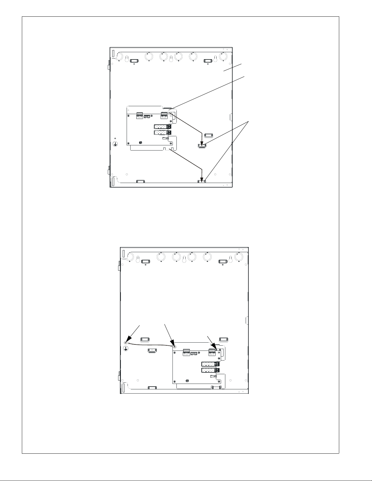
1. Place the ANN-LC flat against the inside back wall of the FACP backbox. Position both bracket mounting tabs above
ANN-LC
backbox
protrusions
Figure 1 Mounting the ANN-LC into the Backbox
FLLCmnttabs.wmf
self-tapping
screw
grounding cable
(p/n 1120-0709)
secured with hex nuts
Figure 2 Securing the ANN-LC to the Backbox
FLLCmnt.wmf
Note: When securing the ANN-LC
to ground, ensure that the ground
cable for the AC mains is installed
first, closest to the backbox.
the two embossed protrusions in the backbox and slide the tabs down into the protrusions.
2. Secure the mounting bracket to the backbox by installing the supplied self-tapping screw into the top embossed
protrusion/tab as illustrated below.
3. Attach the grounding cable from the left corner of the mounting bracket to the backbox grounding stud, securing it
with hex nuts as illustrated below.
IMPORTANT! Only 7 AH or 18 AH batteries will fit in front of the ANN-LC when installed inside the FACP backbox.
If 12 AH batteries are to be used, they must be installed vertically and sit on the left side of the bottom of the backbox.
2 ANN-LC Product Installation Document — P/N LS10158-000FL-E:C 7/28/2015
Page 3

4 Wiring
Figure 3 LC Connector
L
C
c
o
n
n
e
c
t
o
r
2
s
id
e
.
w
m
f
ANN-LC
mounted
in
hub
1
1
1
1
1
1
2
2
2
2
2
2
First
circuit
node
Last
circuit
node
Figure 4 Class B Wiring
F
L
L
C
c
l
a
s
s
B
.
w
m
f
node
node
node
Consult manufacturer’s guidelines for minimum
radius of bend for fiber-optic media
4.1 FACP Wiring
Refer to the MS-9050UD Series (#52413) and MS-9200UDLS Series (#52750) Manuals for wiring the ANN-LC to the
FACP.
4.2 Fiber-Optic Cables
Multi-mode fiber-optic cables must be used. Connections must be made using duplex LC connectors (per IEC 61754-20).
The over-bending of fiber-optic cables can cause breakage. Consult manufacturer’s guidelines for minimum radius of
bend for fiber-optic media.
4.3 Class B Wiring
Class B wiring begins at the MS-9050UD being used as the hub and ends with the last node on the circuit.
ANN-LC Product Installation Document — P/N LS10158-000FL-E:C 7/28/2015 3
Page 4

4.4 Class A Wiring
ANN-LC
mounted
in
hub
1
1
1
1
1
1
2
2
2
2
2
2
First
circuit
node
Last
circuit
node
Figure 5 Class A Wiring
F
L
L
C
c
l
a
s
s
A
.
w
m
f
1
2
1
2
node
node
node
node
node
Consult manufacturer’s
guidelines for minimum
radius of bend for fiberoptic media
Class A wiring begins at the MS-9050UD being used as the hub and returns to the hub after wiring to the last node on the
circuit. In class A wiring, a single open will not result in fragmentation of the circuit. Communication will continue while
the hub and every installed node display a trouble condition on their host FACP..
4 ANN-LC Product Installation Document — P/N LS10158-000FL-E:C 7/28/2015
 Loading...