

Page 1
PRODUCT DESCRIPTION
A new generation of professional movement
Activ8
Activ8 BG
Activ8 Activ8
BG
BGBG
PROFESSIONAL
PASSIVE INFRARED
SHOCK & BREAKAGE
DETECTORS
With PET IMMUNITY
INSTALLATION INSTRUCTIONS
P/N 7101493 REV. A A.Y.
Activ8 BG FEATURES DETECTION PATTE R N
FEATURES
• Quad (Four element) pyrosensor.
• Two independent relay outputs for
GLASS/SHOCK and PIR alarm
signals.
• VLSI SMD technology.
• PIR sensitivity adjustment.
• GLASS sensitivity adjustment.
• SHOCK sensitivity adjustment.
• Volume protection.
• Automatic temperature
compensation.
• Height installation calibrations
free.
• Environmental immunity.
• The Activ8 BG provides pet immunity
up to 25Kg. Pet active bellow 1m.
REMOVAL OF FRONT COVER MOUNTING DETECTOR BASE
Unscrew the holding
screw and open base
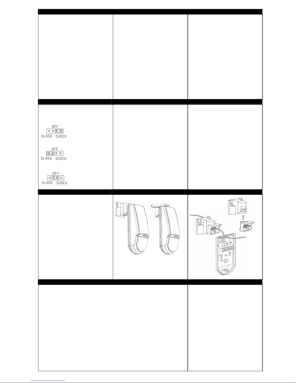
spread spectrum analyzing PIR, Shock & Glass
Breakage detectors.
The detector provides an analysis of
environmental conditions through the entire
movement spread frequency spectrum.
It listens for sounds of breaking glass, which
produces two sequential signals of different
frequencies “SHOCK” and “GLASS”. The unique
phased frequency detection circuitry of this
detector allows detection of both shock signal and
the strong signal of glass breakage creating a
false alarm free detector.
The detector does not need to be attached to the
window, providing volume protection, and
allowing you to protect several windows with one
detector.
15m
1. To remove the front cover, unscrew the holding
screw and gently raise the front cover.
2. To remove the PC board, carefully unscrew the
holding screw located on the PC board.
3. Break out the desired holes for proper installing.
4. The circular and rectangular indentations at the
bottom base are the knockout holes for wire
entry. You may also use mounting holes that are
not in use for running the wiring into the
detector.(For option with bracket - lead wire
through the bracket)
5. Mount the detector base to the wall, corner or
ceiling. (For option with bracket install bracket).
6. Reinstall the PC board by fully tightening the
holding screw. Connect wire to terminal block.
7. Replace the cover by inserting it back in the
appropriate closing pins and screw in the holding
screw.
MOUNTING THE DETECTOR
SELECT MOUNTING LO CATION
DETECTOR INSTALL ATIO N CIRCUIT LAYOUT
TERMINAL BLOCK CONNECTIONS
Terminals 1 & 2 - Marked “ TAMPER ”
If a Tamper function is required connect these
terminals to a 24-hour normally closed protective
zone in the control unit. If the front cover of the
detector is opened, an immediate alarm signal will
be sent to the control unit.
Terminals 3 & 4 - Marked “ R-PIR ”
These are the output PIR relay contacts of the
detector. Connect to a normally closed zone in the
control panel.
Terminal 5 - Marked “ EOL ” – End of line option.
Terminals 6 & 7 - Marked “ R-MIC ”
These are the output MICROPHONE relay
contacts of the detector. Connect to a normally
closed zone in the control panel.
Terminal 8 - Marked “ + ” (+12V)
Connect to a positive Voltage output of 8.2 -16Vdc
source (usually from the alar control unit)
Terminal 9 - Marked “ - ” (gnd)
Connect to the negative Voltage output or ground
of the control panel.
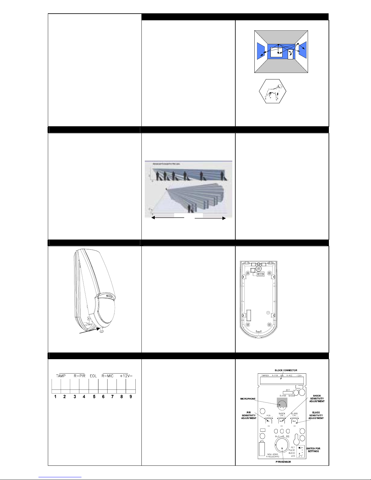
The Activ8 BG provides immunity up to 25Kg.
For better immunity avoid installation in areas
where pets can reach upwards.
TYPICAL INSTALLATIO N
Choose a location in front of the protected
windows, in direct line of sight within 4.5m. In
case of more then one window, place the detector
in the center area facing the windows, make sure
that this location will be most likely to intercept an
intruder, that may across the PIR beams.
See PIR detection beams.
See SHOCK and GLASS detection area.
If heavy blinds or curtains cover the glass, you
must locate the detector behind the blinds on
the window frame or above it, otherwise the
blinds might block the sound.
AVOID THE FOLLOWING LOCATIONS
∗ Facing direct sunlight.
∗ Facing areas subject with temperature
changes.
∗ Areas with air ducts or substantial air flows.
∗ Facing metal doors.
∗ Close to door entrance bells measuring 2” (or
larger) in diameter.
KNOCKOUT HOLES
CC
C
A
A
BBB
A
D
A. Wire access
holes
B. Use for flat wall
mounting
C. Corner mounting -
use all 4 holes.
Sharp left or right
angle mounting use 2 holes (top
C
B
and bottom)
D. For bracket
mounting
Page 2
SETTING UP THE DE TE CTOR
PIR SENSITIVITY ADJUSTMENT
SWITCH 3 OF DIP-4 SWITCH FOR SETTINGS
“PULSE” - provides sensitivity control of PIR
according to the environment.
Position Left – “On” – High sensitivity
For stable environments.
Position Right – “OFF” – Low sensitivity
For harsh environments.
POTENTIOMETER RV1 “PIR” –
adjustment according to protected area
range.
For high-risk locations, the sensitivity should be
adjusted close to MIN (9%). In low risk situations,
the sensitivity should be adjusted closer to MAX
(100%) factory set to 54%.
Always walk test and re-adjust if required.
ADJUSTMENT
SHOCK / GLASS ADJUSTMENT
Use only during testing and setting
SHOCK - for adjustment
of the low frequency
sensitivity with
potentiometer “SHOCK”
GLASS - for
adjustment of the
high frequency
sensitivity with
potentiometer
GLASS
OFF - for regular
operation
SHOCK/GLASS TEST PROCEDURE WALL AND CEILING INSTALLATION OPTIONS
FINAL TESTING
• Make sure to set jumper “GLASS/SHOCK” in
position OFF. When the jumper is in this
position, the detector will detect both shock
and sound frequencies.
•••• To ensure maximum protection against false
alarms, activate any device in the area, which
might automatically cycle pumps, generators,
heating/air conditioning units, etc. If the
devices trigger an alarm, mount the
cycling
unit in a different location.
LED INDIC ATION OF ALARM SIGNAL
SWITCH 1 OF DIP-4 SWITCH FOR SETTINGS
“LED” – provide control of Alarm signal LED
indication.
Position Left – “On” – LED enable.
Position Right – “OFF” – LED disable.
SOUND SENSITIVITY ADJUSTMENT
SWITCH 2 OF DIP-4 SWITCH FOR SETTINGS
“AUDIO” – provide control of sound detection
sensitivity.
Position Left – “On” – reducing the sensitivity of
sound detection by 50%. (Use in small room)
Position Right – “OFF” – LED disable.
PET IMMUNI TY SETTING
SWITCH 4 OF DIP-4 SWITCH FOR SETTINGS
“PET” 15kg – 25kg
Position Left “ON” Immunity to PET up to 15 kg
Position Right “OFF” Immunity to PET up to 25 kg
GLASS BREAK ADJUSTMENT
To adjust the glass break sensitivity, place the
jumper below the GLASS marking. Green
(SHOCK) LED is constantly ON.
Now you can adjust the sensitivity by rotating the
GLASS potentiometer.
Operate the Sound Break Simulator* near the
protected window and rotate the potentiometer
GLASS clock-wise to increase sensitivity, and
counter-clock-wise to decrease sensitivity until
the Yellow and Red LEDs are illuminating for
each glass break sound.
Note:
When the jumper is set for GLASS adjustment,
only the high frequency sound of breaking glass is
detected.
*It is recommended to use GLASS-BREAK
Simulator FG-701 (CROW p/n 004001)
TEST PROCEDURES.
Wait for one minute warm up time after applying
12-Vdc power. Conduct testing with the protected
.
area cleared of all people
unit thoroughly for proper detection.
Walk test
1. Remove front cover.
Set “PULSE” to “ON” position, and set “LED” to
“ON” position.
2. Replace the front cover.
3. Start walking slowly across the detection area.
4. Observe that the red led lights whenever
motion is detected.
5. Allow 5 sec. between each test for the detector
to stabilize.
6. After the walk test is completed, you can set
the “LED” to “OFF” position.
NOTE:
Walk tests should be conducted, at least once a
year, to confirm proper operation and coverage of the
detector.
Make sure to test the
SHOCK ADJUSTMENT
To adjust the shock setting (increase/decrease
sensitivity) place the jumper below the SHOCK Yellow (GLASS) LED is constantly ON.
Now you can adjust the sensitivity by rotating the
potentiometer SHOCK.
Hit gently on the protected glass and rotate the
potentiometer clock-wise to increase sensitivity,
and counter-clock-wise to decrease sensitivity
until the Green and Red LEDs are illuminating for
each hit.
Note:
When the jumper is set for SHOCK adjustment,
only the low frequency of the shock signal prior to
glass breakage is detected.
BRACKET INSTALLATION
Detection Method Quad (Four element) PIR & electret microphone
Detection Speed 0.15 – 3.6 m/sec
Power Input 7.8 - 16 Vdc
Current Draw Alarm PIR :16.5mA; Alarm Shock & Glass 22mA; Alarm all: 18mA
Standby: 16.5 mA
BI Directional Temperature Comp. YES
Pulse Count 1, AUTO
Alarm Period 2 sec
Alarm Output N.C 28Vdc 0.1 A with 10 Ohm series protection resistors
Tamper Switch N.C 28Vdc 0.1A with 10 Ohm series protection resistor – open
when cover is removed
Warm Up Period 60 sec
Operating Temperature -20
RFI Protection 30V/m 10 - 1000MHz
EMI Protection 50,000V of electrical interference from lighting
Visible Light Protection stable against halogen light 2.4m (8ft )or reflected light
Detection range Glass up to 10m ( 90
LEDs indicator Yellow LED (GLASS) - glass break signal for testing & adjustment
Green LED (SHOCK) - shock signal for testing & adjustment
Red LED (ALARM) - alarm signal:
Fleshing light - glass & break detection or glass & shock & PIR
detection
Constant light - PIR detection
Dimensions 121mm x 60mm x 37mm
Weight (inc. battery) 110 gr.
35493AE50
TECHNICAL SPECIFICAT IO N
°
C to +50°C
°
); PIR up to 15m (WA lens)
For Technical Support, please
call 01268 563 247.
 Loading...