

Page 1

Montage-Anschluss-Anleitung
mifare-Leser "Accentic"
RS-485 und Clock/Data Schnittstelle
- mit Tastatur Art.-Nr. 026423
- ohne Tastatur Art.-Nr. 026422
mifare DESFire EV1 Leser "Accentic"
RS-485 Schnittstelle
- mit Tastatur Art.-Nr. 026436.10
- ohne Tastatur Art.-Nr. 026435.10
P30715-10-002-15
2014-04-09
Klasse C für ZKA und EMA
Anerkennungen siehe Kap. 10
D
GB
Änderungen
vorbehalten
Page 2

Montage-Anschluss-Anleitung mifare/DESFire EV1 Leser "Accentic" mit/ohne Tastatur2
Inhaltsverzeichnis Seite
1. Anwendung.................................................................................................................................3
2. Schnittstellen..............................................................................................................................3
3. Funktionsbeschreibung ............................................................................................................4
3.1 mifare allgemein...................................................................................................................4
3.2 mifare DESFire EV1 Leser...................................................................................................4
3.2.1 Sicherheitsniveau......................................................................................................4
3.2.2 Datenträger ...............................................................................................................4
3.2.3 Systemvoraussetzungen...........................................................................................4
4. Montage ......................................................................................................................................5
5. Anschlussplan............................................................................................................................6
5.1 Schnittstellen........................................................................................................................6
5.2 Synchronisation....................................................................................................................7
6. Inbetriebnahme und Konfiguration ..........................................................................................7
6.1 Wichtige Informationen zur Verwendung von Datenträgern.................................................7
6.2 RS-485 Adresse...................................................................................................................8
6.2.1 Einführung.................................................................................................................8
6.2.2 Adressvergabemodus aktivieren...............................................................................9
6.2.3 Adressenanzeige.......................................................................................................9
6.2.4 Adressvergabe manuell über die Programmierung...................................................9
6.2.5 Adressvergabe automatisch mit Datenträger..........................................................10
6.2.6 Adressvergabe manuell über Lesertastatur ............................................................10
6.2.7 Adressvergabe manuell über Lesertastatur im "stand alone" Betrieb .....................11
6.2.8 Adressen löschen....................................................................................................11
6.3 Tastatur-Hintergrundbeleuchtung .......................................................................................11
7. Stand alone Programmiermodus............................................................................................12
7.1 Programmiermodus aktivieren ...........................................................................................12
7.2 Adressen löschen...............................................................................................................12
7.3 Standardwerte laden..........................................................................................................12
7.4 Tastatur-Hintergrundbeleuchtung.......................................................................................12
7.5 Programmiermodus beenden.............................................................................................12
8. LED Anzeige .............................................................................................................................13
9. Technische Daten.....................................................................................................................13
10. VdS-Zulassungen.....................................................................................................................14
11. Zubehör.....................................................................................................................................14
12. Reinigung und Pflege ..............................................................................................................14
Sicherheitshinweise
Lesen Sie die Anleitung sorgfältig und vollständig durch, bevor Sie das Gerät installieren und in
Betrieb nehmen. Sie erhalten wichtige Hinweise zur Montage, Programmierung und Bedienung.
Das Gerät ist nach dem neuesten Stand der Technik gebaut. Benutzen Sie das Gerät nur:
- bestimmungsgemäß und
- in technisch einwandfreiem und ordnungsgemäß eingebautem Zustand
- gemäß den technischen Daten.
Der Hersteller haftet nicht für Schäden, die durch einen bestimmungswidrigen Gebrauch verursacht werden.
Installation, Programmierung sowie Wartungs- und Reparaturarbeiten dürfen nur durch autorisiertes
Fachpersonal durchgeführt werden. Löt- und Anschlussarbeiten innerhalb der gesamten Anlage sind
nur im spannungslosen Zustand vorzunehmen.Lötarbeiten dürfen nur mit einem temperaturgeregelten, vom Netz galvanisch getrennten Lötkolben vorgenommen werden.VDE-Sicherheitsvorschriften
sowie die Vorschriften des örtlichen EVU sind zu beachten.
Die Geräte dürfen nicht in explosionsgefährdeter Umgebung oder in Räumen mit
metall- und kunststoffzersetzenden Dämpfen eingesetzt werden.
Page 3

Montage-Anschluss-Anleitung mifare/DESFire EV1 Leser "Accentic" mit/ohne Tastatur
1. Anwendung
mifare-Leser "Accentic" und mifare DESFire EV1 Leser "Accentic" werden in Zutrittskontroll- und
Einbruchmeldeanlagen als berührungslose Leseeinheiten und Bedienteile eingesetzt.
mifare-Leser "Accentic" stellen verschiedene Schnittstellen zum Anschluss an übergeordnete
Systeme zur Verfügung (s. u.), so dass sich ein breites Spektrum an Anwendungsmöglichkeiten
bietet.
Leistungsmerkmale
- Klares und logisches Bedienkonzept.
- Einfache Inbetriebnahme.
- Einfache RS-485 Adressvergabe, manuell oder automatisch.
- Der Leser ist komplett gegen Feuchtigkeit geschützt.
- Einsatz im Außen- und Innenbereich bei Temperaturen von -25 °C bis +55 °C.
- Einfache Montage mit zwei oder drei Schrauben.
- Der Leser kann direkt auf handelsüblichen uP-Dosen (DIN) montiert werden.
- Die Gehäuse-Oberschale ist nachträglich auswechselbar (in verschiedenen Farben).
Besonderheiten des berührungslosen Lesers:
- Ein neues Auswerteverfahren garantiert äußerst stabile Übertragungen.
- Bei Verwendung von DESFire EV1 Lesern enorme Sicherheitssteigerung durch Verschlüsselungsverfahren AES (Advanced Encryption Standard). Details siehe Kap. 3.2.
- Synchronisation von bis zu 4 dicht nebeneinander montierten Lesern möglich.
- Geringe Stromaufnahme.
3
Besonderheiten der Tastatur:
- Länderneutrale Beschriftung der LEDs und der Tastatur.
- Abriebfeste 10er-Komforttastatur mit 6 zusätzlichen Funktionstasten.
- Taktile und akustische Rückmeldung.
- Nachtdesign mit zeitbegrenzter Hintergrundbeleuchtung.
2. Schnittstellen
mifare-Leser (026422 und 026423):
RS-485: Bidirektionale Schnittstelle mit Modulbus-Protokoll
Clock/Data: Unidirektionale Schnittstelle
Wiegand statt Clock/Data:
mifare DESFire EV1 Leser (026435.10 und 026436.10):
RS-485: Bidirektionale Schnittstelle mit Modulbus-Protokoll
Geeignet für ACS-8, IK3-Auswerteeinheiten und ZK-Türmodul BUS-2
Schnittstellenreichweite bis 1200 m
Datenprotokoll ACS-8, ACS-2 plus, ACT
TTL-Pegel, 4 Bit-Code nach DIN 9785, Ruhepegel HIGH
Schnittstellenreichweite bis 200 m
Sonderausführung auf Anfrage
Geeignet für ACS-8, IK3-Auswerteeinheit BUS-2 und ZK-Türmodul BUS-2
Schnittstellenreichweite bis 1200 m
Page 4

4
Montage-Anschluss-Anleitung mifare/DESFire EV1 Leser "Accentic" mit/ohne Tastatur
3. Funktionsbeschreibung
3.1 mifare allgemein
Die Leser sind für die berührungslose Identifizierung von mifare- n (
z. B. ID-Chipkarten) bestimmt. Bei Lesern mit Tastatur kann für eine Funktionsausführung eine
Kombination aus Datenträger und PIN-Code hergestellt werden.
Um einen Transponder zu lesen, sendet der Leser ein elektromagnetisches Feld mit einer
Frequenz von 13,56 MHz aus. Sobald sich ein Datenträger in diesem Feld befindet, sendet dieser
Daten im "Energiefeld" zum Leser zurück.
Jeder Datenträger ist ein Unikat.
Der übertragene Code wird im Leser so aufbereitet, dass die nachgeschaltete Auswerteeinheit
oder Zentrale die weitere Bearbeitung übernehmen kann, z. B. Schalt- und Steuerfunktionen.
Datenträger Informationsträgern,
3.2 mifare DESFire EV1 Leser
3.2.1 Sicherheitsniveau
Die mifare DESFire EV1 Technologie kann man als den Nachfolger von mifare Classic betrachten,
jedoch mit wesentlich erhöhtem Sicherheitsniveau.
Bei dieser Technologie setzt man auf das in der Kryptologie allgemein anerkannte Verschlüsselungsverfahren AES (Advanced Encryption Standard). Der aktuelle AES-Algorithmus der DESFire
EV1 Leser verwendet einen 128-Bit Schlüssel.
Das Verschlüsselungsverfahren AES gilt als extrem abhör- und manipulationssicher und ist in den
USA für staatliche Dokumente mit höchster Geheimhaltungsstufe zugelassen.
3.2.2 Datenträger
Um das Verschlüsselungsverfahren AES nutzen zu können, werden mifare DESFire EV1 Datenträger benötigt. Weitere Informationen entnehmen Sie bitte unserem aktuellen Katalog.
Die bisherigen mifare Classic Datenträger können nur dann parallel zu den EV1 Datenträgern
verwendet werden, wenn das Verschlüsselungsverfahren AES nicht genutzt wird!
mifare DESFire EV1 Datenträger müssen vor der ersten Verwendung formatiert und
initialisiert werden.
Dazu wird der USB Desktop-Reader mifare Classic & DESFire (Art.-Nr. 026487)
benötigt. Die Vorgehensweise ist in der Anleitung des Lesegeräts beschrieben.
3.2.3 Systemvoraussetzungen
ZKA:
- ACS-8 ab V09.xx
- IQ MultiAccess ab V12.xx
- IQ SystemControl ab V07.xx
EMA:
- IK3 AWE BUS-2 ab V12.xx
- ZK-Türmodul BUS-2 ab V12.xx
- WINFEM Advanced ab V14.xx
Hinweis: Für die Anwendung des Verschlüsselungsverfahrens wird auch bei Einbruchmeldeanla-
gen IQ SystemControl oder IQ MultiAccess benötigt.
Page 5
Montage-Anschluss-Anleitung mifare/DESFire EV1 Leser "Accentic" mit/ohne Tastatur 5
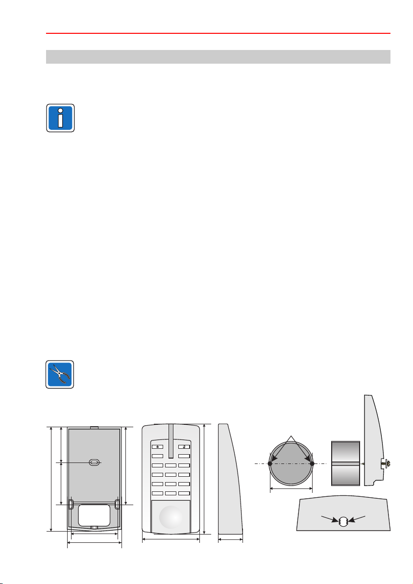
4. Montage
Der Leser ist für den Innen- und Außenbereich geeignet. Die Montage kann direkt an der Wand
oder über einer "Standard-Unterputz-Dose" (DIN) erfolgen. Die Elektronikeinheit ist im Gehäuseboden ohne Befestigung eingelegt und wird mit dem auswechselbaren Gehäuse-Oberteil arretiert.
Bei einem Montageuntergrund aus Metall kann die Reichweite etwas geringer sein als
bei einem nichtmetallischen Untergrund.
Um den Leser optimal bedienen und ablesen zu können, sollte er in einer Höhe von 130 bis 140 cm
vom Fußboden montiert werden.
Bei Außenanwendungen darf der Leser nicht unmittelbar der Witterung ausgesetzt sein!
Falls dies nicht sichergestellt ist, verwenden Sie den Sicht-/Wetterschutz (Art.-Nr. 023501).
Zur Montage wird das Gehäuse-Oberteil im unteren Bereich angehoben und anschließend oben
ausgehängt. Während der Montage des Gehäuseunterteils sollte die Elektronik herausgenommen
werden, um Beschädigungen zu vermeiden.
Im Gehäuseboden sind für Wand- und uP-Dosen-Befestigung zwei Bohrungen mit einem Lochabstand von 60 mm vorgesehen. Für eine sichere Befestigung sollten die Schrauben dem Montageuntergrund angepasst sein.
- In Mauerwerk mit Dübel S6: z. B. Halbrund-Holzschraube mit Schlitz 3,5 x 60 mm
- In Holz, je nach Sorte : Halbrund-Holzschraube mit Schlitz 3,5 x 45 bis 3,5 x 60 mm
- In Metall: Zylinderkopfschraube M3 x 30 mm (min.) mit Unterlegscheibe
- Auf der Standard-uP-Dose: Halbrund-Holzschraube mit Schlitz 3,0 x 40 mm und Unterlegscheibe
Zur weiteren Befestigung kann bei Bedarf die dritte Montagebohrung verwendet werden. Die
Schraubenlänge muss ebenfalls dem Montageuntergrund angepasst werden.
Bei der Montage sollte das Anschlusskabel nach Möglichkeit von hinten durch ein Leerrohr mit
genügend Kabelreserve zugeführt werden.
Bei der Montage auf eine uP-Dose oder Hohlwanddose ist die Dose so einzubauen, dass sich die
Befestigungslöcher in horizontaler Position befinden (siehe Abbildung).
5
Achtung!
Wird der Leser im Außenbereich eingesetzt, ist die Kabeldurchführung auf beiden
Seiten der Wand abzudichten (z. B. mit Gips), um die Bildung von Kondenswasser zu
vermeiden!
Abmessungen in mm
F i
3
2
1
100,5
134,5
54 46,5
Gehäuseboden
ohne Elektronik
Kabeleinführung
60
69,5
Die Abmessungen von Lesern mit und ohne Tastatur sind identisch.
5
4
7 8 9
0
r
75
6
142
3
32
Standard uP-Dose (DIN)
Befestigungslöcher
60 mm
60 mm
Einkerbungen beachten
Einkerbungen beachten
VdS
VdS
Zum Verschließen des Gehäuses unten in
der Mitte eine der beigefügten Plomben
eindrücken. Das Gehäuse lässt sich ohne
Zerstörung der Plombe nicht mehr öffnen.
Page 6

6
Montage-Anschluss-Anleitung mifare/DESFire EV1 Leser "Accentic" mit/ohne Tastatur
5. Anschlussplan
Speziell für Prüf- und Vormontageaufbauten sind am Kabel des Lesers werkseitig Stecker
angelötet. Für die endgültige Installation müssen sie in der Regel abgeschnitten werden.
5.1 Schnittstellen
Der Leser stellt die Schnittstellen RS-485 und Clock/Data zur Verfügung, die alternativ verwendet
werden können (Details siehe Kap. 2 "Schnittstellen").
RS-485: Wird diese Schnittstelle verwendet, wird sie bei der Inbetriebnahme automatisch
erkannt.
Der Leser kann bis zu 1200 m abgesetzt werden. Als Anschlusskabel wird ³Cat 5
empfohlen.
Ist der Leser der letzte Teilnehmer auf dem RS-485-Bus, muss vor dem Leser ein Verteiler
mit einem 120 W Abschlusswiderstand (von A nach B) installiert werden.
Weitere Informationen entnehmen Sie bitte der jeweiligen AWE-/Zentralenbeschreibung.
Clock/Data: Für eine sichere Funktion ist zu beachten, dass das 6 m lange Anschlusskabel auf max.
200 m verlängert werden darf (Voraussetzung: keine externe Störspannung).
Zur Verlängerung kann z. B. ein Kabel der Ausführung JY(ST)Y 6x2x0,6 mm (DIN VDE
0815) Verwendung finden.
Achtung:
Werden die Datenleitungen
F i
2
1
5
4
7
8 9
0
r
A und B vertauscht, ist keine
Funktion vorhanden!
3
6
3
Leser mit/ohne Tastatur
gr/rs
(frei)
Schirm
rt
bl
ge
ws
sw
vl
gr
rt/bl
gn
bn
rs
nur mifare-Leser (026422 und 026423)
+U_b (9 V bis 30 V DC)
0 V
A (D)
B (D*)
RS-485
Synchronisation
Enable RS-485
CLK (D1)
DATA (D0)
LED grün
LED gelb
LED rot
Page 7
Montage-Anschluss-Anleitung mifare/DESFire EV1 Leser "Accentic" mit/ohne Tastatur
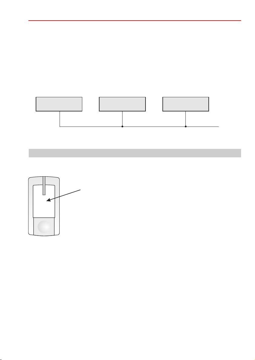
5.2 Synchronisation
Um eine gegenseitige Beeinflussung von dicht nebeneinander montierten Lesern zu vermeiden,
müssen diese über die Leitung "Synchronisation" (sw) miteinander verbunden werden. Bis zu 4
Leser können so miteinander synchronisiert werden (unabhängig von der verwendeten Schnittstelle).
Die Synchronisation ist etwa bei einem Abstand von £1 m (Richtwert) erforderlich.
Immer derjenige Datenträger, der zuerst erkannt wird, ist während des Lesevorgangs bevor-
rechtigt. Die anderen beteiligten Leser sind inaktiv geschaltet. Nach einer Nachlaufzeit von ca. 5
Sek. sind sie wieder bereit.
7
Leser 1 Leser 2
sw sw sw
Leitung für die
Synchronisation
Leser 3
6. Inbetriebnahme und Konfiguration
6.1 Wichtige Informationen zur Verwendung von Datenträgern
Der Datenträger sollte etwa mittig in dieses Feld gehalten werden.
Halten Sie ausschließlich den gewünschten Datenträger in das
X
Lesefeld!
Um bei der Datenträger-Benutzung eine große Übertragungsreichweite zu
erzielen, ist während der Übertragung ein relativ hoher Strom erforderlich
(<55 mA).
Ohne Datenträger-Benutzung reduziert sich der Stromverbrauch im Mittel auf
<30 mA.
max. 4
Page 8

8
Montage-Anschluss-Anleitung mifare/DESFire EV1 Leser "Accentic" mit/ohne Tastatur
6.2 RS-485 Adresse
6.2.1 Einführung
Jeder am RS-485-Bus betriebene Leser muss mit einer eigenen Adresse versehen werden. Eine
Plausibilitätsprüfung im System verhindert, dass Adressen mehrfach belegt werden können.
Möglicher Adressbereich: abhängig von der verwendeten AWE/Zentrale.
Für die Zuweisung der Adressen besitzen die Leser einen speziellen "Adressvergabemodus". Die
Art der Programmierung des Adressvergabemodus richtet sich nach den Komponenten der Anlage.
Übersicht über die verschiedenen Möglichkeiten der Adressvergabe:
1.) Manuell über Programmierung (siehe 6.2.4)
Die Seriennummer des Lesers plus die gewünschte Adresse wird über die Programmierung
eingegeben. Die Adresse wird anschließend im Leser abgespeichert.
Empfohlene Standardmethode.
2.) Automatisch mit Datenträger (siehe 6.2.5)
Mit einem beliebigen Datenträger im Lesefeld des Lesers wird der Vorgang gestartet. Die
Adresse wird automatisch vergeben und anschließend im Leser abgespeichert. Solange der
Adressvergabemodus aktiv ist, können auf diese Weise mehrere Leser nacheinander automatisch mit Adressen versehen werden.
Empfehlung:
Geeignet bei kleineren Entfernungen zwischen Zentrale und den einzelnen Lesern.
3.) Manuell über Lesertastatur (siehe 6.2.6)
(Nur möglich bei Lesern mit Tastatur.)
Die Zuweisung einer Adresse erfolgt durch Tastatureingabe am Leser.
Empfehlung:
Geeignet, wenn einem Leser vor Ort eine bestimmte Adresse zugewiesen werden soll.
4.) Manuell über Lesertastatur im "stand alone" Betrieb (siehe 6.2.7)
(Nur möglich bei Lesern mit Tastatur.)
Am Leser muss nur die Betriebsspannung angeschlossen sein, eine Verbindung zur Zentrale
ist nicht erforderlich. Die Zuweisung einer Adresse erfolgt durch Tastatureingabe am Leser.
Empfehlung:
Geeignet für allgemeine Service- und Testzwecke.
ACHTUNG: Eine Plausibilitätsprüfung ist hier nicht möglich!
Page 9
Montage-Anschluss-Anleitung mifare/DESFire EV1 Leser "Accentic" mit/ohne Tastatur
9
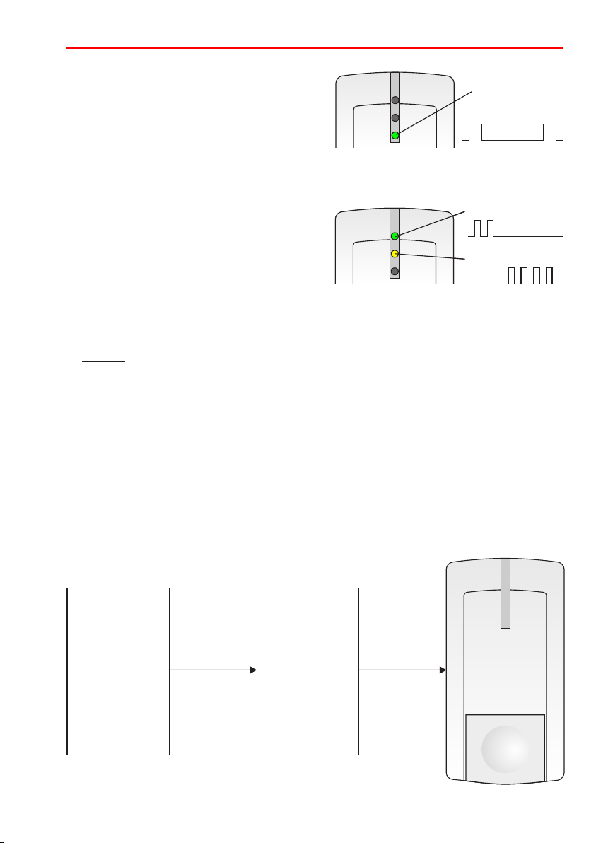
6.2.2 Adressvergabemodus aktivieren
Adressvergabemodus über die Programmierung aktivieren (durch AWE/Zentrale). Der aktivierte Adressvergabemodus wird durch Blinken der unteren LED
grün angezeigt (kurzes Aufleuchten mit längerer
Pause).
Die Abschaltung des Adressvergabemodus erfolgt über die Programmierung.
6.2.3 Adressenanzeige
Adressvergabemodus muss aktiviert sein.
Der
Die Adressenanzeige dient der Kontrolle neu ange-
legter Adressen und der späteren Kontrolle.
- Zehnerstelle: obere LED (grün)
Jedes Blinken zeigt die Zehnerstelle der vergebenen Adresse an.
Beispiel: 2 x blinken = 20
- Einerstelle: mittlere LED (gelb)
Jedes Blinken zeigt die Einerstelle der vergebenen Adresse an.
Beispiel: 4 x blinken = 4
Im Anschluss daran wird wieder der Adressvergabemodus durch die untere LED angezeigt.
Adressenanzeige wiederholen:
Datenträger kurz ins Lesefeld des Lesers halten. Eine kurze akustische Quittierung bestätigt die
Anzeigeaufforderung und startet erneut den Anzeigeablauf. Die untere LED bleibt während der
Adressenanzeige dunkel.
F i
Die dargestellte Anzeige entspricht Adresse 24
Adressvergabemode Anzeige
Zehnerstelle
Einerstelle
6.2.4 Adressvergabe manuell über Programmierung
Seriennummer eines neuen Lesers plus die gewünschte Adresse über die Programmierung
eingeben. Die AWE/Zentrale sendet Seriennummer plus Adresse an den Leser. Wenn die
empfangene Seriennummer mit der im Leser hinterlegten Nummer übereinstimmt, übernimmt der
Leser die Adresse und speichert sie ab.
Beispiel:
Programmierung
Seriennummer
des Lesers
plus Adresse
eingeben
Seriennummer
+ Adresse
ACS-8
IK3
ZK-TM
Seriennummer
+ Adresse
RS-485
Page 10
10
Montage-Anschluss-Anleitung mifare/DESFire EV1 Leser "Accentic" mit/ohne Tastatur311
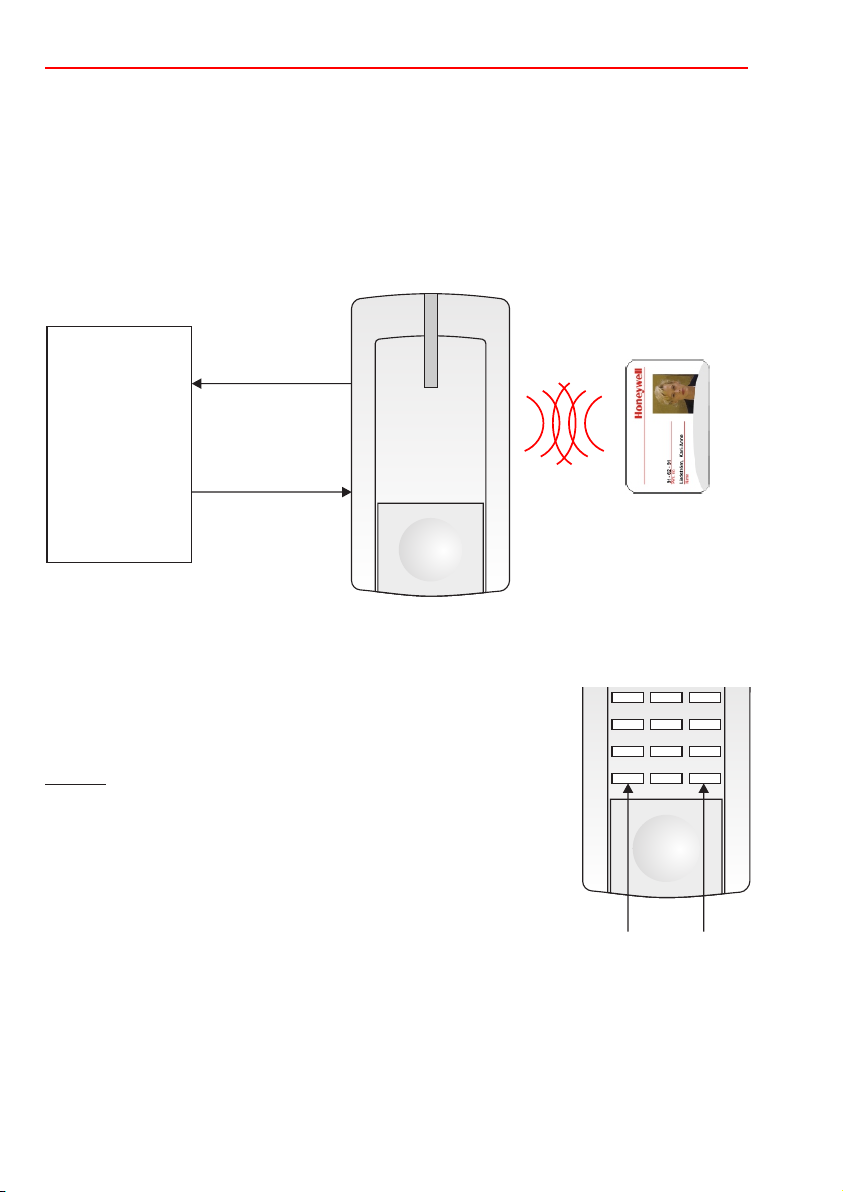
6.2.5 utomatisch mit
Adressvergabe a Datenträger
Der Adressvergabemodus muss aktiviert sein.
Beliebigen mifare-Datenträger in den Lesebereich halten.
Der Leser sendet jetzt seine Seriennummer an die AWE/Zentrale. Diese fügt dieser Nummer eine
noch freie Adresse hinzu und sendet Seriennummer plus Adresse an den Leser zurück. Nach einer
kurzen Wartezeit wird die Adresse dauerhaft im Leser abgespeichert.
Quittierung: Nach einer Anzeigepause von ca. 1 Sek. wird die neu vergebene Adresse durch die
LEDs angezeigt (siehe 6.2.3).
Seriennummer
ACS-8
IK3
ZK-TM
Serien
fügt der -
nummer eine
freie Adresse
hinzu
6.2.6 anuell über Lesertastatur
Adressvergabe m
Seriennummer
+ Adresse
Der Adressvergabemodus muss aktiviert sein.
Bei dieser Adressvergabe kann einem Leser vor Ort eine bestimmte
Adresse zugewiesen werden. Die Plausibilitätsprüfung in der AWE/
Zentrale verhindert, dass eine Adresse mehrfach belegt werden kann.
Hinweis:
1
4
7 8 9
r
3
2
5
6
0
- Bei jeder Tastenbetätigung erfolgt eine Quittierung (Klick).
- Eine begonnene Adresseingabe kann durch X wieder verworfen werden.
Adresse 1- oder 2-stellig eingegeben und mit OK (Taste 3) bestätigen. Die
Adresse wird zur AWE/Zentrale gesendet und dort überprüft.
Positiv-Quittierung
Nach einer Anzeigepause von ca. 1 Sek. wird die neu vergebene Adresse
durch die LEDs angezeigt (siehe 6.2.3).
Löschen
Verwerfen
Bestätigung
OK
Negativ-Quittierung
Ist die Adresse bereits belegt, so wird diese Adresse dem Leser nicht zugewiesen und es erfolgt
keine Adressenanzeige.
Adresse ändern
Neue Adresse 1- oder 2-stellig eingegeben und mit OK bestätigen. (Quittierung und Anzeige wie
oben). Alle zugeordneten Parameter werden von der alten zur neuen Adresse übertragen und die
alte Adresse wird wieder frei.
Page 11

Montage-Anschluss-Anleitung mifare/DESFire EV1 Leser "Accentic" mit/ohne Tastatur
6.2 .7 Adressvergabe über die Lesertastatur im "stand alone" Betrieb
Bei dieser Adressvergabe ist keine Plausibilitätsprüfung möglich. Achten Sie bitte
darauf, dass in einem System eine Adresse nicht doppelt oder mehrfach vergeben wird!
Adresse vergeben
Leser neu an die Betriebsspannung anschließen (Initialisierung). Der RS-485-Bus kann, muss aber
nicht angeschlossen sein.
Adresse 1- oder 2-stellig eingeben und mit OK (Taste 3) bestätigen.
Adresse ändern
Eine Überschreibung der Adresse ist möglich, solange der Leser von der AWE/Zentrale noch nicht
aufgenommen ist und die Betriebsspannung nicht unterbrochen wurde.
Adresse löschen
Im spannungslosen Zustand die Tasten "1", "7" und "X" gleichzeitig drücken und festhalten.
Betriebsspannung anlegen, danach Tasten loslassen. Die Adresse ist jetzt gelöscht.
Hinweis: Wird der Leser später mit der AWE/Zentrale verbunden, so wird die eingegebene Adresse
zusammen mit der Leser-Seriennummer zur AWE/Zentrale gesendet und dort abgespeichert. Im Anzeigemodus (siehe 6.2.3) kann jetzt die Adresse überprüft werden.
6.2.8 Adresse(n) löschen
- Über die Programmierung
- oder im "stand alone" Betrieb (siehe 6.2.7)
- oder im "stand alone" Programmiermodus (siehe Kap. 7.).
6.3 Tastatur-Hintergrundbeleuchtung
Die Hintergrundbeleuchtung für den Ruhezustand (kein Bedienvorgang) wird über die Programmierung der AWE/Zentrale oder im "stand alone" Programmiermodus (siehe 7.4) festgelegt.
Dabei kann die Helligkeit in 16 Stufen von "abgeschaltet" bis "volle Helligkeit" eingestellt werden.
Die volle Helligkeit während der Bedienung ist davon nicht betroffen.
Page 12

12
Montage-Anschluss-Anleitung mifare/DESFire EV1 Leser "Accentic" mit/ohne Tastatur
7. Stand alone Programmiermodus
Zur Durchführung der Programmierung in diesem Modus ist nur die Betriebsspannung erforderlich.
Bitte beachten:
Über die RS-485 Schnittstelle können die eingestellten Parameter jederzeit von der AWE/
Zentrale aus geändert (überschrieben) werden.
Bei der Clock/Data Schnittstelle können die Parameter nur über eine erneute stand alone
Programmierung geändert werden.
(nur Leser mit Tastatur)
7.1 Programmiermodus aktivieren
Im spannungslosen Zustand die Tasten mit nebenstehenden Symbolen
gleichzeitig drücken und festhalten.
Betriebsspannung anlegen. Sobald der Programmiermodus aktiviert ist,
blinken die drei LEDs im Sekundentakt. Tasten loslassen.
i
7.2 Adresse löschen
Taste betätigen: eine bereits vergebene Adresse wird gelöscht.
1
7.3 Standardwerte laden
Taste betätigen: der Auslieferungszustand wird hergestellt:
- Hintergrundbeleuchtung: im Ruhezustand ausgeschaltet
Eine bereits vergebene Adresse bleibt erhalten.
2
7.4 Tastatur-Hintergrundbeleuchtung
Die Helligkeit der Hintergrundbeleuchtung für den Ruhezustand kann mit den Tasten "4" und "5" stufenweise eingestellt werden.
Taste Beginnend mit der vollen Helligkeit wird bei jeder Betätigung der Taste die
Taste Die Helligkeit wird stufenweise erhöht bis zum Maximum.
4
Beleuchtung stufenweise dunkler, bis sie ganz abgeschaltet ist.
5
7.5 Programmiermodus beenden
Taste betätigen.
X
Page 13

Montage-Anschluss-Anleitung mifare/DESFire EV1 Leser "Accentic" mit/ohne Tastatur
8. LED-Anzeige
13
grün
gelb
rot/grün
Die LEDs des Lesers werden im Normalbetrieb grundsätzlich von der AWE/
Zentrale angesteuert. Abhängig von der eingesetzten AWE/Zentrale ist die
Funktion festgelegt oder kann über die Programmierung definiert werden.
Sonderfall: Die untere LED blinkt abwechselnd rot/grün.
Bei dieser Anzeige liegt eine Systemstörung vor. In diesem Fall wenden Sie sich
bitte an unsere Anwendungstechnik.
9. Technische Daten
Betriebsnennspannung 12 V DC/24 V DC
Betriebsspannungsbereich 9 V bis 30 V DC
Stromaufnahme im stand by Betrieb <30 mA (im Mittel)
Zeitbegrenzter Schreib-Lesebetrieb <55 mA (inkl. Zustandsanzeigen)
(Zeitbegrenzte Nachlaufzeit nach der letzten Datenträger-Annäherung 5 Sek.)
Hintergrundbeleuchtung <4 mA (zeitbegrenzt für 5 Sek. bis zu 8 mA)
Montageuntergrund beliebig, auch auf Metall
Lesedistanz
- mifare-Leser >4 cm bis 8 cm, je nach Datenträgertyp und
- mifare DESFire EV1 Leser ca. 1,5 cm (nur Karten)
Schnittstellenreichweite:
- RS-485 bis 1200 m
- Clock/Data bis 200 m
Anschlusskabel 12-adrig abgeschirmt (5-adrig bei DESFire EV1 Lesern)
Schutzart nach IP 65
Umweltklasse gemäß VdS III
Betriebstemperaturbereich -25 °C bis +55 °C
Gehäuse-Abmessungen (B x H x T) 75 x 142 x 32 mm
Farbe weißaluminium (ähnlich RAL 9006)
1)
Die angegebene Lesedistanz kann nur bei Verwendung von ID-Datenträgern aus unserem
Haus garantiert werden.
1)
Montageort-/umgebung des Lesers
Länge 6 m
EN 60529
Die Geräte
- mifare-Leser "Accentic" mit Tastatur, Art.-Nr. 026423
- mifare-Leser "Accentic" ohne Tastatur, Art.-Nr. 026422
- mifare DESFire EV1 Leser "Accentic" mit Tastatur, Art.-Nr. 026436.10
- mifare DESFire EV1 Leser "Accentic" ohne Tastatur, Art.-Nr. 026435.10
entsprechen bei bestimmungsgemäßer Anwendung den grundlegenden Anforderungen
gemäß Artikel 3 der R&TTE-Richtlinie 1999/5/EG.
Die EG-Konformitätserklärung steht auf unserer Homepage im Service/Downloadbereich unter
info.security.de@honeywell.com zum Download bereit.
Page 14

14
Montage-Anschluss-Anleitung mifare/DESFire EV1 Leser "Accentic" mit/ohne Tastatur
10. VdS-Anerkennungen
026422 mifare-Leser ohne Tast. Z107003 (ZKA, Klasse C), G107016 (EMT, Klasse C)
026423 mifare-Leser mit Tast. Z107004 (ZKA, Klasse C), G107017 (EMT, Klasse C)
026435.10 mifare DESFire EV1 Leser o. T. Z111001 (ZK, Klasse C), G111004 (EMT, Klasse C)
026436.10 mifare DESFire EV1 Leser m. T. Z111002 (ZK, Klasse C), G111005 (EMT, Klasse C)
11. Zubehör
Gehäuse-Oberschalen für Leser mit Tastatur:
023314 weißaluminium (ähnlich RAL 9006) VPE = 3 Stück
023315 reinweiß (ähnlich RAL 9010) VPE = 3 Stück
023316.99 anthrazit (atlasgrau metallic) VPE = 3 Stück
Gehäuse-Oberschalen für Leser ohne Tastatur:
023317 reinweiß (ähnlich RAL 9010) VPE = 3 Stück
023318 anthrazit (atlasgrau metallic) VPE = 3 Stück
023319 weißaluminium (ähnlich RAL 9006) VPE = 3 Stück
Montage-Zubehör:
023501 Sicht-/Wetterschutz
023329 Montageplatte VPE = 3 Stück
023324 Gehäuseboden mit Deckelkontakt für Accentic-Leser
Zubehör für DESFire EV1 Datenträger:
026487 USB Desktop-Reader mifare Classic & DESFire (zwingend erforderlich)
12. Reinigung und Pflege
Gehäuse und Tastatur:
Das Gehäuse und die Tastatur können bei Bedarf mit einem weichen Tuch gereinigt werden.
Bei starker Verschmutzung können Sie ein mit Wasser angefeuchtetes Tuch benutzen .
Verwenden Sie keine Reinigungsmittel, Scheuermittel oder Lösungsmittel wie Spiritus,
Alkohol oder Benzin!
Page 15

Notizen
15Montage-Anschluss-Anleitung mifare/DESFire EV1 Leser "Accentic" mit/ohne Tastatur
Page 16

Honeywell Security Group
Novar GmbH
Johannes-Mauthe-Straße 14
D-72458 Albstadt
www.honeywell.com/security/de
P30715-10-002-15
2014-04-09
© 2014 Novar GmbH
Page 17

Mounting and Connection Instructions
mifare reader "Accentic"
RS-485 and Clock/Data interface
- with keypad Item no. 026423
- without keypad Item no. 026422
mifare DESFire EV1 reader "Accentic"
RS-485 interface
- with keypad Item no. 026436.10
- without keypad Item no. 026435.10
P30715-10-002-15
2014-04-09
D
GB
Subject to change
without notice
Page 18

Mounting and Connection Instructions mifare/DESFire EV1 reader "Accentic" with/without keypad
18
Table of Contents Page
1. Application................................................................................................................................19
2. Interfaces ..................................................................................................................................19
3. Functional description.............................................................................................................20
3.1 mifare (general)..................................................................................................................20
3.2 mifare DESFire EV1 readers..............................................................................................20
3.2.1 Security features .....................................................................................................20
3.2.2 Data carriers............................................................................................................20
3.2.3 System conditions ...................................................................................................20
4. Mounting ...................................................................................................................................21
5. Connection diagram.................................................................................................................22
5.1 Interfaces ...........................................................................................................................22
5.2 Synchronization .................................................................................................................23
6. Start-up and configuration ......................................................................................................23
6.1 Important informations about usage of data carriers...........................................................23
6.2 RS-485 address .................................................................................................................24
6.2.1 Introduction .............................................................................................................24
6.2.2 Activate adress allocation mode..............................................................................25
6.2.3 Address indicator.....................................................................................................25
6.2.4 Manual address allocation via central control unit....................................................25
6.2.5 Automatic address allocation with data carrier.........................................................26
6.2.6 Manual address allocation via reader keypad..........................................................26
6.2.7 Manual address allocation via reader keypad, stand alone operating mode............27
6.2.8 Clear addresses ......................................................................................................27
6.3 Keypad lighting...................................................................................................................27
7. Stand alone programming mode .............................................................................................28
7.1 Activate programming mode ..............................................................................................28
7.2 Clear address.....................................................................................................................28
7.3 Load standard values.........................................................................................................28
7.4 Keypad lighting...................................................................................................................28
7.5 Exit programming mode.....................................................................................................28
8. LED indication ..........................................................................................................................29
9. Technical data...........................................................................................................................29
10. VdS approvals ..........................................................................................................................30
11. Accessories ..............................................................................................................................30
12. Cleaning and care.....................................................................................................................30
13. FCC Statements........................................................................................................................31
Safety notes
Read the instructions carefully and thoroughly before installing the device and putting it into
operation. They contain important information on assembly, programming and operation.
The device is a state-of-the-art product. Only use the device:
The manufacturer is not responsible for damage that is caused by use not in accordance with regulations.
Installation, programming as well as maintenance and repair work may only be carried out by
authorized, skilled personnel. Soldering and connection work should only be carried out inside the
entire system when it is deenergized. Soldering work should only be carried out using a temperaturecontrolled soldering bit that is galvanically separated from the power supply. Observe the VDE safety
instructions as well as the regulations of the local power supply company.
- In accordance with regulations and
- When it is in a technically correct state
- In accordance with technical data.
Do not use the reader in a potentially explosive environment or in rooms with metal or
plastic decomposing vapours.
Page 19

Mounting and Connection Instructions mifare/DESFire EV1 reader "Accentic" with/without keypad
19
1. Application
The mifare-readers "Accentic" and mifare DESFire EV1 readers "Accentic" are used in intrusion
detection systems and access control systems as reading units and operating units.
The mifare readers features different interfaces (see Chapter 2.) offering a wide spectrum of
applications.
Performance features
- Clear and logical operating concept.
- Simple start-up.
- Simple RS-485 address allocation, manual or automatic.
- The reader is completely protected against humidity.
- For use outdoors and indoors at temperatures from -25 °C to +55 °C.
- Simple assembly with two or three screws.
- The reader can be directly mounted on commercially available f.m. sockets (DIN).
- The front of the housing is replaceable (in different colours).
Special reader features:
- New evaluation process ensures extremely stable transmission.
- By use of DESFire EV1 readers extreme safety is available because of the encoding procedure
AES (Advanced Encryption Standard). See chapter 3.2.
- Synchronization of max. 4 readers installed close to one another.
- Low current consumption
Special keypad features:
- Neutral labelling of LEDs and keypad.
- Abrasion-resistant 10 key keypad with 6 additional functional keys.
- Tactile and acoustical acknowledgement.
- Night design with time-limited luminous background.
2. Interfaces
mifare readers (026422 und 026423):
RS-485: Bidirectional interface with "Modulbus" protocol
Clock/Data: Unidirectional interface
Wiegand instead of Clock/Data:
mifare DESFire EV1 readers (026435.10 und 026436.10):
RS-485: Bidirectional interface with "Modulbus" protocol
Suitable for ACS-8, IK3 Evaluation unit and Door controller module for MB
Interface range up to 1200 m
TTL-level, 4 bit code according to DIN 9785, active = LOW
Data protocol ACS-8, ACS-2 plus, ACT
Interface range up to 200 m
Special type on request
Suitable for ACS-8, IK3 Evaluation unit BUS-2 and Door controller module for MB
Interface range up to 1200 m
Page 20

Mounting and Connection Instructions mifare/DESFire EV1 reader "Accentic" with/without keypad
20
3. Functional description
3.1 mifare (general)
The readers are designed for contactless identification of mifare data carriers data carriers e.g. ID
chipcards).
A combination of data carrier and PIN can be used for performing functions via the keypad.
In order to read a data carrier an electromagnetic field with a frequency of 13,56 MHz is transmitted
from the reader unit. As soon as a data carrier enters this field, it transmits data in the "power field"
to the reader.
The individual code of every data carrier renders it unique.
The transmitted code is prepared in the reader so that the connected controller (evaluation unit or
central control unit) can continue the processing e.g. switching and control functions.
(
3.2 mifare DESFire EV1 readers
3.2.1 Security features
The mifare DESFire EV1 technology is the follower of the mifare classic system, however it has a
higher security class.
The mifare DESFire EV1 technology use the common accepted encoding procedure AES
(Advanced Encryption Standard). The current encoding procedure AES of DESFire EV1 readers
uses a 128 bit key.
The encoding procedure AES is known as extremely tap-proof and tamper-resistant. In th USA it is
approved for government documents in the highest security ratings.
3.2.2 Data carriers
To be able to use the encryption AES, mifare DESFire EV1 data carriers are needed.
For further information, refer to our current catalog.
The previous mifare classic data carrier can only be used parallel to EV1 data carriers if the
encryption AES is unused!
Before first use the mifate DESFire EV1 data carriers must be formatted and
initialized.
Therefore the USB Desktop-reader mifare Classic & DESFire (Item no. 026487) must
be used. The procedure is described within the operating instructions of the USB
Desktop-reader.
3.2.3 System conditions
ACS:
- ACS-8 from V09.xx
- IQ MultiAccess from V12.xx
- IQ SystemControl from V07.xx
IDS:
- IK3 EU BUS-2 from V12.xx
- Door controller module for MB from V12.xx
- WINFEM Advanced from V14.xx
Note: To use the encoding procedure, IQ SystemControl or IQ MultiAccess is required also for IDS.
Page 21

Mounting and Connection Instructions mifare/DESFire EV1 reader "Accentic" with/without keypad
21
4. Mounting
The reader is suitable for indoor and outdoor use. Mount directly on the wall or use a "standard f.m.
socket". The electronic unit is inserted in the back of the housing and locked into position with the
housing front (replaceable).
For mounting surfaces of metal, the transmission range of the data carrier may be lower
than that of non-metallic surfaces.
In order to operate and read the keypad/indication optimally, install the reader at a height of 130 to
140 cm above the floor.
When used outdoors, do not expose the reader directly to the weather!
If necessary, use the plastic housing (weather/view) Item no. 023501.
To mount, lift the housing front at the bottom and unhook at the top. When installing the housing back,
remove the electronics to avoid damage.
The housing back has two 60 mm boreholes for wall and f.m. sockets. To fix securely, use screws that
are suitable for the mounting surface in question.
- In masonry with S6 plug: E.g. semi-circular wood screw with slot 3.5 x 60 mm
- In wood, depending on type: Semi-circular wood screw with slot 3.5 x 45 to 3.5 x 60 mm
- In metal: Fillister head screw M3 x 30 mm (min.) with washer
- On the standard s.m. socket Semi-circular wood screw with slot 3.0 x 40 mm and washer
For additional fixing, the third borehole can be used. Choose the correct screw length for the
mounting surface.
When mounting, feed the connecting cable, if possible, from the back through an empty pipe
allowing sufficient spare cable.
When mounting on an f.m. socket or on a cavity wall, install the socket so that the fixing holes are
horizontal (see illustration).
Attention!
If the reader is to be used outdoors, the cable bushing must be sealed on both sides of
the wall, (e.g. with plaster) to prevent condensation from forming!
Dimensions (in mm)
F i
3
2
1
100,5
134,5
54 46,5
Housing back
without electronics
Cable entry
60
69,5
The dimensions of readers with and without keypad are identical.
5
6
4
7
8 9
0
r
75
142
3
32
f.m. socket (DIN)
Fixing holes
60 mm
Observe notches
VdS
To lock the housing press in one of the
enclosed seals at the bottom. The housing
cannot be opened without destroying the
seal.
Page 22

22
Mounting and Connection Instructions mifare/DESFire EV1 reader "Accentic" with/without keypad
5. Connection diagram
A plug has been soldered to the cable of the reader at the factory especially for test and
premounting sets. For the final installation, it usually has to be cut off.
5.1 Interfaces
The reader has the interfaces RS-485 and clock/data that can be used alternatively (Details see
Chapter 2. "Interfaces").
RS-485: When started up, the reader automatically identifies the RS-485 interface.
The reader can be used remotely at a distance of max. 1200 m. We recommend
using a Cat 5 connecting cable.
If the reader is the last user on the RS-485 bus, a distributor with a 120 Ohm
terminating resistor (from A to B) must be installed in front of the reader.
For further information, refer to the description of the corresponding controller.
Clock/Data: To ensure reliable functioning, ensure that a possible extension of the 6 m connecting
cable does not exceed 200 m (Condition: no external interference voltage).
A JY(ST)Y 6x2x0.6 mm cable (DIN VDE 0815) can be used for extension purposes.
Attention:
Do not confuse the data
F i
2
1
5
4
7
8 9
0
r
lines A and B, otherwise the
device will not function!
3
6
3
Reader with/without keypad
grey/pink
(free)
Shield
red
blue
yellow
white
black
violet
grey
red/blue
green
brown
pink
only mifare readers (026422 and 026423)
+U_b (9 V to 30 V DC)
0 V
A (D)
B (D*)
RS-485
Synchronization
Enable RS-485
CLK (D1)
DATA (D0)
LED green
LED yellow
LED red
Page 23

Mounting and Connection Instructions mifare/DESFire EV1 reader "Accentic" with/without keypad
23
5.2 Synchronization
In order to prevent densely packed readers from affecting one another, they must be connected to
one another via the "Synchronization" line (black). Up to 4 readers can be synchronized in this
manner (irrespective of the used interface).
Synchronization is required at a distance of £ (approximate value).
The data carrier that is identified first has priority during the read process. The other readers
involved are inactive. After a period of 5 sec. they are reactivated.
1 m
Reader 1 Reader 2
black
Synchronization line
black black
Reader 3
6. Start-up and configuration
6.1 Important informations about usage of data carriers
The data carrier should be held approximately in the middle of this field.
Ensure that the desired data carrier is held separately in the
reading range.
X
In order to achieve a greater transmission range when using the data carrier, a
relatively high current is required during transmission (<55 mA).
Without data carrier transmission the reader automatically switches from active
mode to low current mode and thus reduces the current consumption on
average to <30 mA.
max. 4
Page 24

Mounting and Connection Instructions mifare/DESFire EV1 reader "Accentic" with/without keypad
24
6.2 RS-485 address
6.2.1 Introduction
Every reader operated at the RS-485 module bus must have its own address. A plausibility check
in the system prevents addresses from being allocated several times.
Possible address range: depending on the controller
The allocation of the addresses varies. The following information is intended to assist you in
choosing the best methods for your special requirement. A detailed description on the individual
methods can be found in the following chapters.
1.) Manually via the central control unit (see 6.2.4)
Enter the serial number of the reader plus the desired address via the programming of the
central control unit. The address is then stored in the reader.
Recommended standard methods.
2.) Automatically with data carrier (see 6.2.5)
Start the process with a data carrier in the reading area of the reader. The address is
allocated automatically and then stored in the reader. As long as the address allocation
mode is active, several readers can be automatically allocated addresses in succession.
Recommendation:
Suitable for shorter distances between the central control unit and the individual readers.
(Manual input of the serial numbers of the readers is not required).
3.) Manually via reader keypad (see 6.2.6)
An address is allocated via the keypad at the reader.
Recommended:
When a specific address has to be allocated to an reader on site.
4.) Manually via reader keypad - stand alone operating mode (see 6.2.7)
Only the operating voltage requires connecting at the reader. The address allocation mode
must not be active, neither is a connection to the ACS-8 necessary.
An address is allocated via the keypad at the reader.
Recommended:
When servicing or testing.
ATTENTION: A plausibility check is not possible!
Page 25

Mounting and Connection Instructions mifare/DESFire EV1 reader "Accentic" with/without keypad
25
6.2.2
Activate address allocation mode via the
programming ( ).
The address allocation mode at the reader is
indicated by the bottom flashing green LED (lights
up briefly followed by a long pause).
Switch off the address allocation mode via the programming.
6.2.3 Address indication
The address allocation mode must be activated.
The address indicator is for monitoring newly defined
addresses or for a later control.
- Tens digit: Upper LED (green)
- Units digit: Middle LED (yellow)
The address allocation mode is then displayed in the lower LED.
Repeat indication of addresses:
Hold the data carrier briefly in the reading range of the reader. A brief acoustical acknowledgement
confirms the request to indicate and restarts the indication sequence. The bottom LED remains dark
when the address is indicated.
Activate address allocation mode
controller
Each flash indicates the tens digit of the allocated
address.
Example: Flashes 2 x = 20
Each flash indicates the ones digit of the allocated address.
Example: Flashes 4 x = 4
Address allocation
mode indicator
Tens digit (green)
Units digit (yellow)
This example shows address 24
6.2.4 Manual address allocation via central control unit
Enter the serial number of a new reader plus the desired address when programming the central
control unit. The controller transmits the serial number plus the address to the reader. If the
received serial number corresponds with the number defined in the reader, the reader stores the
address.
Example:
Programming
Enter serial
number
of the operating unit
plus adress
serial number
+ address
ACS-8
IK3
DCM
serial number
+ address
RS-485
Page 26

Mounting and Connection Instructions mifare/DESFire EV1 reader "Accentic" with/without keypad
26
6.2.5 Automatic address allocation with data carrier
The address allocation mode must be activated.
Hold an mifare data carrier in the reading range. The reader now transmits the serial number to the
controller. The controller allocates a free address to this number and transmits the serial number
plus the address back to the reader. After a brief interval, the reader stores the address
permanently.
Address acknowledgement: After approx. 1 sec. the LEDs indicate the allocated address (see
6.2.3).
Serial number
ACS-8
IK3
DCM
allocates a free
address to the
serial number
Serial number
+ address
6.2.6 Manual address allocation via reader keypad
The address allocation mode must be activated.
When using this allocation mode, a specific address can be allocated to an
reader on site. The plausibility check in the controller prevents an address
from being allocated more than once.
Note:
1
4
7
r
- Every activated key is acknowledged by a click.
- An address entry can be rejected by an X.
Enter the new address with 1 or 2 digits and acknowledge with OK (key ).
3
The address is transmitted to the controller and checked.
Positive acknowledgement
After remaining blank for approx. 1 sec. the LEDs indicate the newly
allocated address (see 6.2.3).
Delete
Reject
Negative acknowledgement
If the address is already occupied, it is not allocated to the reader and there is no address indicated.
Change address
Enter new address with 1 or 2 digits and acknowledge with OK. (Acknowledgement and indication as
described above). All allocated parameters are transmitted from the old address to the new one so that
the old address can be re-allocated.
3
2
5
6
8 9
0
3
Confirmation
OK
Page 27

Mounting and Connection Instructions mifare/DESFire EV1 reader "Accentic" with/without keypad
27
6.2.7 Manual address allocation via reader keypad, "stand alone" operating
mode
With this form of address allocation a plausibility check is not possible. This means that
an address collision may occur later during operation. (Double or multiple addressing).
Allocate address
Reconnect the reader only to the operating voltage.
Enter the address via the keypad (1 or 2 digit) and confirm with the OK button (3). When the
operating voltage is interrupted, the address is saved in the reader.
Overwrite address
The address can be overwritten as long as the reader has not been linked by the controller and the
operating voltage is not interrupted.
Clear address
An address is cleared when the keys "1", "7" and "X" are pressed simultaneously and keep
pressed whilst the operating voltage is re-applied.
An address can also be deleted in the programming mode „Stand alone“ (see 7.2)
Note: If the reader is connected at a later stage to the controller, the entered address is
transmitted together with the serial number of the reader to the controller and stored.
6.2.8 Clear addresses
- Via programming
- or in "stand alone" operating mode (see 6.2.7)
- or in "stand alone" programming mode (see Chapter 7.)
6.3 Keypad lighting
If permanent backlighting is desired, the brightness for the no-load status can be set in 16 stages
from "off" to "maximum brightness" via the programming of the controller or in the "stand alone"
programming mode, (see 7.4).
Maximum brightness during operation is not affected.
Page 28

Mounting and Connection Instructions mifare/DESFire EV1 reader "Accentic" with/without keypad
28
7. Stand alone programming mode (only readers with keypad)
To program in this mode, only the operating voltage is required.
Please note!
The settings of the parameters can be modified via the RS-485 interface of a connected
controller.
It is not possible to make any changes of the parameters via Clock/Data (as it is only
unidirectional). In this case it is necessary to make a "stand alone" programming.
7.1 Activate programming mode
Press the 3 keys (with the symbols as shown) simultaneously and keep
pressed.
Apply the operating voltage. As soon as the programming mode is
activated, the three LEDs flash every second. Release keys.
7.2 Clear address
i
Activate to clear an already allocated address.
1
7.3 Load standard values
Activate to create the condition on delivery.
- Illumination: deactivated for the non load status
An already allocated address is not altered.
2
7.4 Keypad lighting
If you require permanent illumination, the brightness for the no-load status can be set in steps
using button "4" and "5".
Key "4": Every time the button is activated, the illumination becomes gradually darker until
Key "5": The brightness increases in steps until it reaches maximum brightness.
4
it is fully switched off.
5
The set value is permanently saved when the programming mode is exited.
7.5 Exit programming mode
Áctivate key.
X
Page 29

Mounting and Connection Instructions mifare/DESFire EV1 reader "Accentic" with/without keypad
8. LED indication
29
green
yellow
red/green
The LEDs will be driven by the connected controller. Depending on the
connected controller the functions are fixed or can be defined via the
programming.
Special case: the LED below flashes red and green alternating.
This means a system error. In this case you should contact our support.
9. Technical data
Rated operating voltage 12 V / 24 V DC
Operating voltage range 9 V to 30 V DC
Current consumption in stand by mode <30 mA (on average)
Time-limited write/read mode <55 mA (incl. status indication)
(Time lag after last data carrier reactivation 5 sec.)
Luminous background <4 mA (time-limited for 5 sec. max. 8 mA)
Mounting surface Any surface, also metal
Reading distance
- mifare readers >4 cm up to 8 cm, depending on data carrier typ
- mifare DESFire EV1 readers aprox. 1.5 cm (only cards)
Interface range:
- RS-485 up to 1200 m
- Clock/Data up to 200 m
Connecting cable 12-core (5-core DESFire EV1 reader), shielded, length 6 m
Protection category as per IP 65
Environmental class as per VdS III
Operating temperature range -25 °C to +55 °C
Housing dimensions (W x H x D) 75 x 142 x 32 mm
Colour White aluminium (similar to RAL 9006)
1)
The denoted reading distance can only be garanteed by using data carriers provided by our
company.
1)
EN 60529
Brightness settable
and mounting site- /surroundings Interfaces
The following readers
- mifare reader "Accentic" with keypad Item no. 026423
- mifare reader "Accentic" without keypad Item no. 026422
- mifare DESFire EV1 reader "Accentic" with keypad Item no. 026436.10
- mifare DESFire EV1 reader "Accentic" without keypad Item no. 026435.10
comply with the essential requirements of the R&TTE 1999/5/EC Directive, if used for
its intended use.
The EC-Declaration of Conformity can be downloaded from our homepage (Service / Download).
info.security.de@honeywell.com
Page 30

Mounting and Connection Instructions mifare/DESFire EV1 reader "Accentic" with/without keypad
30
10. VdS-approvals
026422 mifare reader w/o. keypad Z107003 (ACS, Class C), G107016 (IDS, Class C)
026423 mifare reader w. keypad Z107004 (ACS, Class C), G107017 (IDS, Class C)
026435.10 mifare DESFire EV1 reader w/o. k. Z111001 (ACS, Class C), G111004 (IDS, Class C)
026436.10 mifare DESFire EV1 reader w. k. Z111002 (ACS, Class C), G111005 (IDS, Class C)
11. Accessories
Fronts for readers with keypad:
023314 white aluminium (similar to RAL 9006) PU = 3 pce.
023315 pure white (similar to RAL 9010) PU = 3 pce.
023316.99 anthracite (satin grey metallic) PU = 3 pce.
Fronts for readers without keypad:
023317 pure white (similar to RAL 9010) PU = 3 pce.
023318 anthracite (satin grey metallic) PU = 3 pce.
023319 white aluminium (similar to RAL 9006) PU = 3 pce.
Mounting accessories:
023501 Plastic shield weather/view
023329 Mounting plate PU = 3 pce.
023324 Housing bottom with cover contact for Accentic readers
Accessory for DESFire EV1 data carriers:
026487 USB Desktop reader mifare Classic & DESFire (mandatory)
12. Cleaning and care
Housing and keypad:
The housing and keypad can be cleaned when necessary with a soft cloth.
Use a cloth moistened by water if heavily soiled.
Do not use cleaning agents, abrasives or solvents such as spirits, alcohol or
petrol!
Page 31

Mounting and Connection Instructions mifare/DESFire EV1 reader "Accentic" with/without keypad
13. FCC Statements
The devices can contain the transmitter modules:
mifare reader module IC:6587A-X0402100 / FCC ID: UA2X0402100
12.1 Statement required by 15.19 and RSS-210
This device complies with Part 15 of the FCC Rules and with RSS-210 of Industry Canada.
Operation is subject to the following two conditions:
(1) this device may not cause harmful interference, and
(2) this device must accept any interference received, including interference that may
cause undesired operation.
12.2 Statement required by 15.21
31
Warning: Changes or modifications made to this equipment not
12.3 Statement required by 15.105
This equipment has been tested and found to comply with the limits for a Class B digital device,
pursuant to Part 15 of the FCC Rules. These limits are designed to provide reasonable protection
against harmful interference in a residential installation. This equipment generates, uses and can
radiate radio frequency energy and, if not installed and used in accordance with the instructions,
may cause harmful interference to radio communications. However, there is no guarantee that
interference to radio or television reception, which can be determined by turning the equipment off
and on, the user is encouraged to try to correct the interference by one or more of the following
measures:
Reorient or relocate the receiving antenna.
Increase the separation between the equipment and receiver.
Connect the equipment into an outlet on a circuit different from that to which the
receiver is connected.
Consult the dealer or an experienced radio/TV technician for help.
expressly approved by Honeywell may void the FCC
authorization to operate this equipment.
Page 32

Honeywell Security Group
Novar GmbH
Johannes-Mauthe-Straße 14
D-72458 Albstadt
www.honeywell.com/security/de
P30715-10-002-15
2014-04-09
© 2014 Novar GmbH
 Loading...