

Page 1
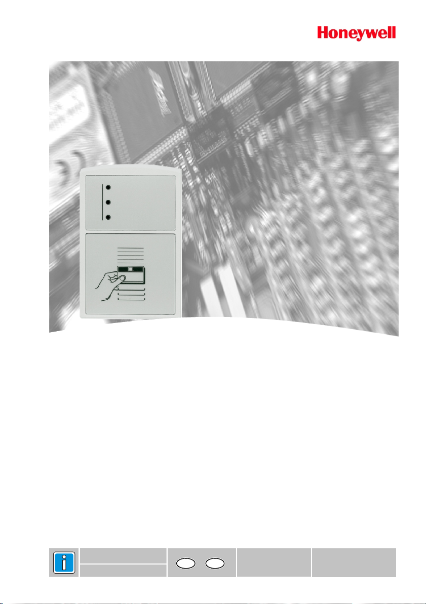
Installationsanleitung
ACC 50
Art.-Nr. 026389.00, 026389.10
Zutrittskontrollsystem für bis zu 99 berührungslose Karten
P31050-02-002-03
26.02.2007
GBD
Änderungen vorbehalten
Page 2

2 Installationsanleitung ACC 50
Inhaltsverzeichnis Seite
1. Sicherheitshinweise.............................................................................................................2
2. Anwendungen / Funktionen.................................................................................................3
3. Montage .............................................................................................................................3
3.1 Montageort...................................................................................................................3
3.2 Leitungslängen / Typen.................................................................................................4
3.3 Befestigung des ACC 50 ..............................................................................................4
4. Anschlussplan.....................................................................................................................6
5. Anschluss der extenen Komponenten..................................................................................7
6. Handling der ID-Karten........................................................................................................9
7. Bedeutung des Programmierkartensatzes ............................................................................9
8. Erstellen des Programmierkartensatzes..............................................................................10
9. Einstellung der DIP-Schalter...............................................................................................11
10. Inbetriebnahme .................................................................................................................12
11. Betriebsanzeigen...............................................................................................................12
12. Zeitzonen..........................................................................................................................13
13. ID-Karten berechtigen / sperren .........................................................................................14
14. Zubehör............................................................................................................................15
14.1 Netzteil.....................................................................................................................15
15. Technische Daten..............................................................................................................16
16. EU-Konformitätserklärung..................................................................................................17
1. Sicherheitshinweise
Lesen Sie diese Anleitung sorgfältig und vollständig durch, bevor Sie das Gerät
installieren und in Betrieb nehmen. Sie erhalten wichtige Hinweise zur
Programmierung und Bedienung.
Benutzen Sie das Gerät nur
- bestimmungsgemäß und
- in technisch einwandfreiem und ordnungsgemäß eingebautem Zustand
- gemäß den technischen Daten.
Der Hersteller haftet nicht für Schäden, die durch einen bestimmungswidrigen Gebrauch
verursacht wurden.
Bewahren Sie ihre Programmierkarten an einem sicheren Ort auf, um Manipulationen der
Zutrittsrechte zu verhindern.
Installation, Wartungs- und Reparaturarbeiten dürfen nur durch autorisiertes
Fachpersonal durchgeführt werden.
Löt- und Anschlussarbeiten sind nur im spannungslosen Zustand vorzunehmen.
Lötarbeiten dürfen nur mit einem temperaturgeregelten, vom Netz galvanisch
getrennten Lötkolben ausgeführt werden.
VDE-Sicherheitsvorschriften sowie die Vorschriften des örtlichen EVU beachten.
Gefahr: Das Gerät darf nicht in explosionsgefährdeten Räumen, oder in
Entsorgung: Die Verpackung ist aus folgenden wiederverwertbaren Stoffen
Räumen mit metall- und kunststoffzersetzenden Dämpfen eingesetzt
werden.
hergestellt: Pappe, Polystyrol PS, Polyäthylen PE.
Page 3

Installationsanleitung ACC 50 3
2. Anwendungen / Funktionen
l Das ACC 50 kontrolliert und überwacht den Zutritt einer Tür.
l Bei Benutzung einer berechtigten ID-Karte wird der Türöffner freigegeben und die
l Außerdem übernimmt das ACC 50 die Türüberwachung. Bei Einsatz eines Türöffners mit
l Ein externer Türöffnertaster, der sich im gesicherten Bereich befindet, ermöglicht ein
l Durch den Anschluss einer externen Zeitschaltuhr lassen sich 2 Zeitbereiche definieren,
l Die Programmierung des ACC 50 erfolgt durch den Programmierkartensatz. Bei der
dazugehörige Tür kann geöffnet werden. Die Freigabezeit richtet sich nach der Einstellung
der DIP-Schalter.
Rückmeldekontakt meldet dieser, ob die Tür geöffnet oder geschlossen ist. Nach Ablauf
der eingestellten Überwachungszeit kann das ACC 50 an einer Einbruchmeldeanlage oder
durch einen Alarmgeber (Signallampe, Blitzsignal, Sirene etc.) mittels Schließkontakt
einen Alarm auslösen.
manuelles Freigeben der Tür.
denen die ID-Karten zugeordnet werden können.
Beispiel: Zeitzone "A" = 07:00 Uhr ... 19:00 Uhr = Schalter geöffnet
Zeitzone "B" = 19:00 Uhr ... 07:00 Uhr = Schalter geschlossen
Je nach Zuordnung erhalten bestimmte Personen nur in Zeitzone "A", nur in Zeitzone "B"
oder in beiden Zeitzonen Zutritt.
Programmierung des Programmierkartensatzes speichert das ACC 50 die Nummer der
Programmierkarten einmalig ab. Danach sind andere Programmierkarten nicht mehr
berechtigt, d.h. andere Kartensätze werden abgewiesen.
3. Montage
3.1 Montageort
Werden mehrere ACC 50-Geräte montiert, muss zwischen den Geräten ein Mindestabstand von 1m
eingehalten werden um eine gegenseitige Beeinflussung auszuschließen.
Das ACC 50 darf nicht direkt auf Metall montiert werden. Die Lesedistanz würde stark vermindert
werden. Ist trotzdem eine Montage auf einer Metallfläche unumgänglich, muss der Adaptersockel
Art.-Nr. 022 197 (im Lieferumfang enthalten) verwendet werden, um die volle Lesedistanz zu
erreichen.
Direkte Sonneneinstrahlung vermeiden.
Das ACC 50 darf keinen kunststoffzersetzenden Dämpfen ausgesetzt werden.
Page 4
4 Installationsanleitung ACC 50
3.2 Leitungslängen/Typen
Zum Anschluss der externen Komponenten verwenden Sie bitte folgende Leitungstypen. Beachten
Sie hierbei die maximale Leitungslänge.
Türöffner mit Rückmeldekontakt 40m J-Y(St)Y 2x2x0,6mm Ø
Türöffnertaster 40m J-Y(St)Y 2x0,6mm Ø
Alarmrelais-Ausgang 40m J-Y(St)Y 2x0,6mm Ø
Zeitschaltuhr 40m J-Y(St)Y 2x0,6mm Ø
Drucker 5m LifYCY 5x2x0,6mm Ø
Spannungsversorgung nach Berechnung H03VV-F 2x1,5mm
2
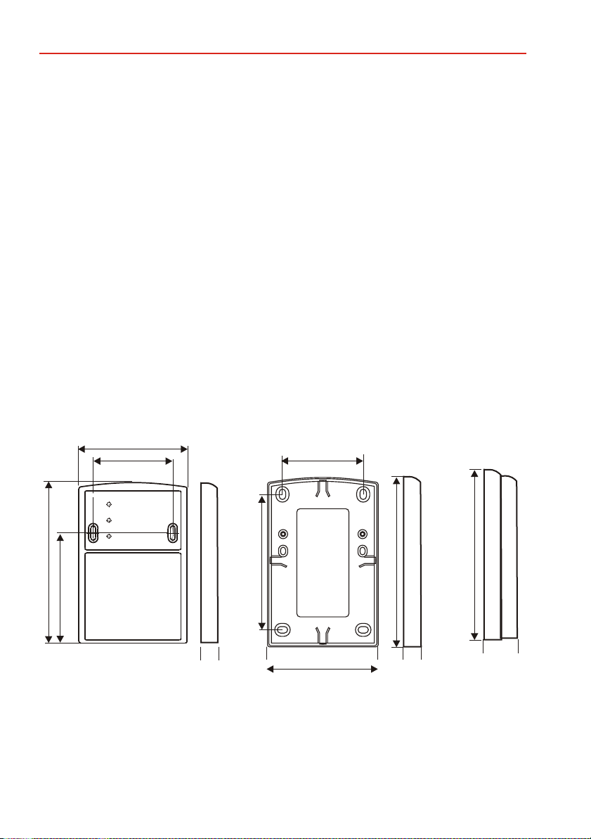
3.3 Befestigung des ACC 50
Die Befestigungsbohrungen des ACC 50 sind so ausgelegt, daß die Montage direkt über einer uPInstallationsdose oder Hohlwandinstallationsdose (Ø60mm) erfolgen kann. Das Gerät kann auch
direkt über einen Leerrohrausgang montiert werden (siehe nachfolgende Zeichnungen). Dabei ist
eine Kabelreserve entweder in der Installationsdose oder in der Verteilerdose zu berücksichtigen.
Leser
82
60
126
Adaptersockel
4
0
1
62
Leser incl. Sockel
132
2
3
1
85
12
86
12
24
Page 5
Installationsanleitung ACC 50 5
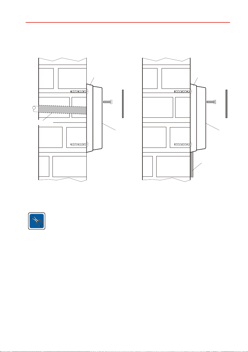
Montagevarianten ACC 50
Leerrohr
Montage über Leerrohr
Montagesockel
Decorfolie
ACC 50
aP-Montage
Montagesockel
Anschlussleitung
Für die Montage im Außenbereich empfehlen wir Ihnen den Einsatz des beiliegenden
Montagesockels 022197.
Bei einer Montage mit Montagesockel, besteht die Möglickeit des seitlichen oder
vertikalen Kabelabgangs für eine aP-Verlegung des Anschlußkabels.
Decorfolie
ACC 50
Nach Beendigung der Installation ist die beiliegende selbstklebende Decorfolie anzubringen,
wodurch die Befestigungsschrauben verdeckt werden.
Page 6
6 Installationsanleitung ACC 50
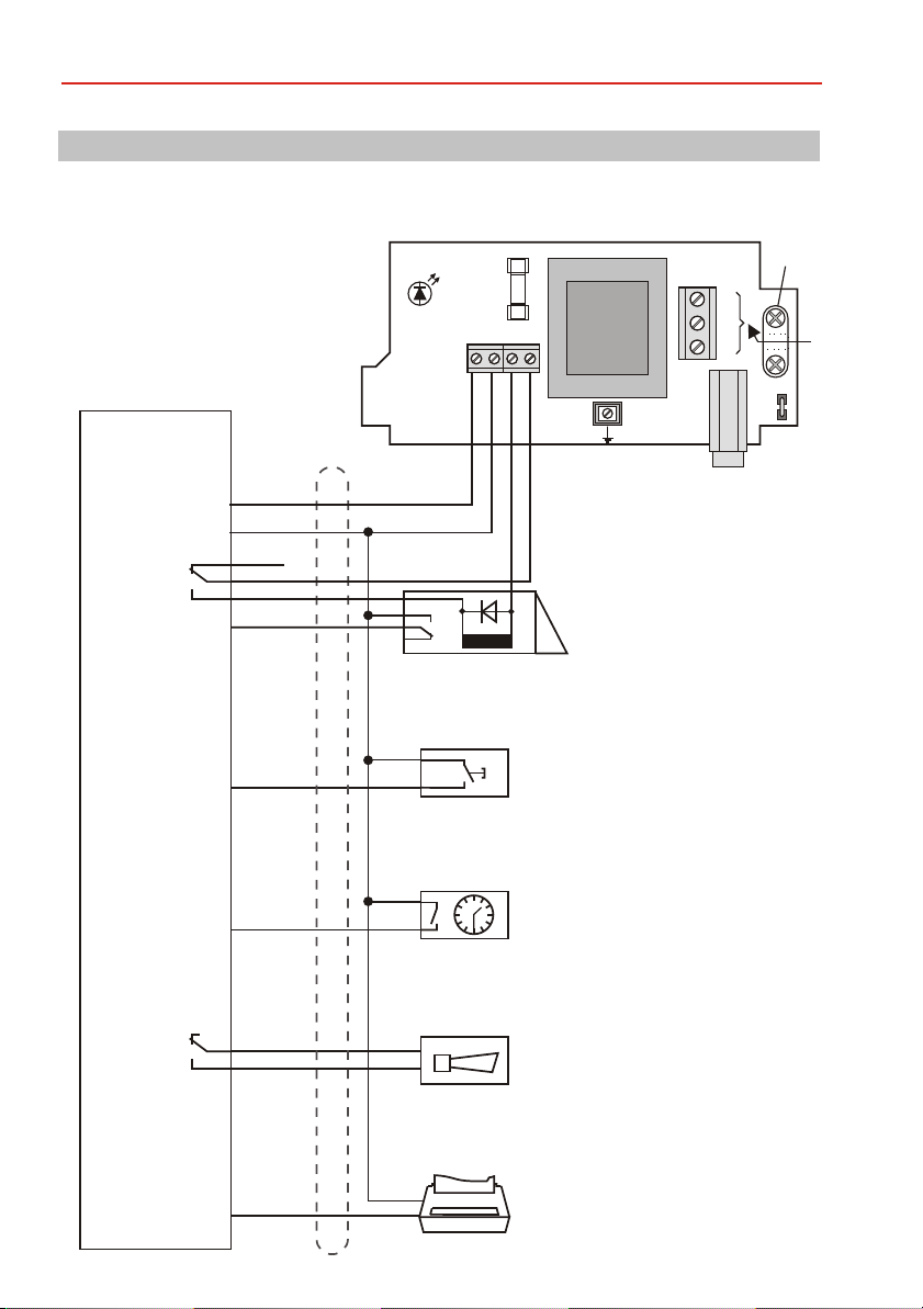
4. Anschlussplan
Es dürfen nur Türöffner verwendet werden,
die mit einer Freilaufdiode ausgestattet sind
und deren Stromaufnahme 250mA nicht
übersteigt.
Alle Niederspannungsleitungen müssen
abgeschirmt sein!
Bei Verwendung von Türöffnern ohne
Rückmeldekontakt muss violett nach
schwarz gebrückt werden!
LED grün
Betriebsanzeige
KL2
Si2
0,63AF
1 2 3 4
KL3
KL1
Tr1
Si1
PE
0,1AT
Zugentlastung
L1
N
PE
DB1
Türöffner-
relais
ACC 50
Alarm-
relais
rot
schwarz
rosa
weiß
grau
violett
grün
braun
blau
grau/rosa
+12V DC
stabilisiert
+
+12V DC
nicht stabilisiert
nicht geglättet
0V
0V
Arbeitsstrom-Türöffner
-
mit Rückmeldekontakt
und Freilaufdiode
Wird ein Ruhestrom-Türöffner verwendet, so wird
anstelle der grauen Leitung die rosa Leitung
angeschlossen.
externer Türöffnertaster
Zeitschaltuhr für
Zonendefinition
- Einbruchmelderzentrale,
- Zeitrelais für akustischen
Signalgeber,
- optischer Signalgeber,
- ...
rot/blau
Serieller Drucker
Page 7

Installationsanleitung ACC 50 7
5. Anschluss der externen Komponenten
Achtung!
Es dürfen nur Gleichspannungstüröffner verwendet werden, die mit einer
Freilaufdiode ausgestattet sind und deren Stromaufnahme 250mA nicht übersteigt.
Alle Niederspannungsleitungen müssen abgeschirmt sein!
Wird der Rückmeldekontakt nicht verwendet, muss violett nach schwarz gebrückt
werden!
Freigaberelais
Wenn Sie einen Arbeitsstrom-Türöffner verwenden, schließen Sie die weiße und die graue Leitung
gemäß dem Anschlussplan an. Bei einem Ruhestrom-Türöffner verwenden Sie die weiße und die
rosa Leitung.
Türüberwachungskontakt
Der Türüberwachungskontakt wird an die violette und schwarze Leitung angeschlossen. Wird der
Türüberwachungskontakt nicht benutzt, muss die violette Leitung auf die schwarze Leitung gelegt
werden.
Bei geschlossener Tür muss der Türüberwachungskontakt geschlossen sein.
Besteht die Möglichkeit, die gesicherte Tür von innen zu öffnen, so wird beim Verlassen des Raumes
der Türüberwachungskontakt betätigt und somit das Alarmrelais angesteuert. In diesem Fall sollte
der Türüberwachungskontakt nicht benutzt werden.
externer Türöffnertaster
Wird ein externer Türöffnertaster benötigt, wird dieser an der grünen und der schwarzen Leitung
angeschlossen. Mit dem externen Türöffnertaster kann die Tür freigegeben werden (Besucher). Er
ermöglicht auch das Verlassen des Raumes bei angeschlossenem Türüberwachungskontakt.
Das Freigaberelais bleibt für die eingestellte Freigabezeit angezogen.
Alarmrelais
Das Alarmrelais ist ein potentialfreier Kontakt, der im Normalbetrieb geöffnet ist. Tritt ein Alarm auf, so
zieht das Alarmrelais an und der Kontakt wird geschlossen. Die Leitungen grau/rosa und blau können
somit benutzt werden für:
-Alarmauswertung für Einbruchmelderanlage
-Zeitrelais für akustischen Signalgeber
-optischer Signalgeber
- ...
Ursachen für das Anziehen des Alarmrelais sind:
- Tür nach der Überwachungszeit immer noch offen
- Tür unerlaubt geöffnet (Türüberwachungskontakt hat angesprochen)
Das Alarmrelais wird erst zurückgesetzt, wenn die Ursache für den Alarm beseitigt ist.
Page 8

8 Installationsanleitung ACC 50
Zeitschaltuhr
Über den Eingang "Zeitschaltuhr" kann zwischen 2 Berechtigungsebenen gewählt werden.
braun + schwarz geöffnet = Zeitzone "A"
braun + schwarz geschossen = Zeitzone "B"
Die Zeitschaltuhr muss einen potentialfreien Kontakt aufweisen.
Drucker
Über einen Drucker können die Zutrittskontrollbuchungen (siehe Beispiel) ausgedruckt werden.
Der Drucker muss hierzu folgende Merkmale aufweisen:
- serielle RS 232 C - Schnittstelle
- 600 Baud
- 8 Datenbits
- EVEN-Parity
- 1 Stopbit
Die Leitung RxD des Druckers (siehe Handbuch des Druckers) wird mit der rot/blauen Leitung des
ACC 50 verbunden.
Sie erhalten Angaben über:
-Karteninhalt der eingelesenen ID-Karte
-Türstatus: valid (= zutrittsberechtigt, Tür wird freigegeben)
invalid (= keine Zutrittsberechtigung, Tür bleibt gesperrt)
Beispiel: 0000060808010504 invalid
0000060808010505 invalid
0000060808010506 valid
0000060808010507 invalid
0000060808010508 valid
Page 9

Installationsanleitung ACC 50 9
6. Handling der ID-Karten
Die Karten werden sicher und eindeutig erkannt, vorausgesetzt die Entfernung zum ACC 50 wird
nicht überschritten. Der Empfangsteil des ACC 50 liegt im oberen Drittel. Der optimale Kartenabstand
beträgt 5-10 cm, wobei die Karte möglichst parallel zum Gerät gehalten werden soll. Um ein sicheres
Lesen der Karte zu erreichen, genügt bereits ein Vorbeiziehen am ACC 50.
Prinzip der berührungslosen Karten:
Das Innenleben der Karte besteht aus einem Schwingkreis und einem Mikro-Chip, der den
gespeicherten Code der Karte trägt. Das ACC 50 strahlt ein schwaches elektromagnetisches Feld
ab, das in Resonanz mit dem Schwingkreis der Karte ist. Die Karte moduliert jetzt die
Empfangsfrequenz mit ihrem Bit-Muster, das vom ACC 50 empfangen wird.
Sämtliche berührungslosen Karten unseres Unternehmens sind Unikate. Jede existierende Karte
besitzt eine andere Dateninformation.
7. Bedeutung des Programmierkartensatzes
Der Programmierkartensatz besteht aus 3 Karten:
RESET-Karte PROGRAM-Karte CLEAR-Karte
Mit diesen Karten können Sie in den jeweiligen Modus des ACC 50 wechseln. Der
Programmierkartensatz wird vom Errichter programmiert (siehe "Erstellen des
Programmierkartensatzes").
RESET-Karte:
Achtung! Löscht den Datenspeicher komplett und bringt das ACC 50 in den
Grundzustand! Anwendung nur bei Erstinbetriebnahmne oder wenn alle ID-Karten
gelöscht werden sollen.
PROGRAM-Karte:
Das ACC 50 schaltet in den Programmiermodus. Es werden alle nachfolgend eingelesenen IDKarten in Abhängigkeit des Eingangs "Zeitschaltuhr" berechtigt.
braun-schwarz geöffnet = Zeitzone "A"
braun-schwarz geschlossen = Zeitzone "B"
CLEAR-Karte:
Das ACC 50 schaltet in den Sperrmodus. Im Sperrmodus können bisher berechtigte
ID-Karten gesperrt werden. Alle nachfolgend eingelesenen Karten werden im ACC 50 gesperrt.
Zu beachten ist dabei die zugehörige Zeitzone "A" und "B".
Page 10

10 Installationsanleitung ACC 50
8. Erstellen des Programmierkartensatzes
1. Beschriften Sie drei (willkürliche) ID-Karten mit den entsprechenden beiliegenden Aufklebern:
Karte 1 RESET
Karte 2 PROGRAM
Karte 3 CLEAR
In dieser Reihenfolge werden anschließend die Karten programmiert.
2. Nachdem Sie die Karten beschriftet und sortiert haben, stellen Sie die DIP-Schalter
folgendermaßen ein:
Schalter 1 2 3 4 5 6 7 8
3. Unterbrechen Sie kurzzeitig die Betriebsspannung, damit die Schalteränderung wirksam wird.
4. Nach Anlegen der Betriebsspannung leuchtet die gelbe und die rote LED.
Warten Sie, bis die rote LED erloschen ist (ca. 10 Sekunden).
Das ACC 50 ist jetzt zur Programmiersatzerstellung bereit.
1 0 0 1 1 1 1 1
(0=off, 1=on)
5. RESET-Karte ins Feld bringen: Grüne LED leuchtet kurz.
PROGRAM-Karte ins Feld bringen: Grüne LED blinkt kurz.
CLEAR-Karte ins Feld bringen: Rote LED blinkt kurz.
6. Bringen Sie die DIP-Schalter wieder in Normalstellung und unterbrechen Sie kurz die
Betriebsspannung. Programmierung des Kartensatzes beendet.
Anmerkung: Werden mehrere ACC 50 montiert, so kann der Programmierkarten-
satz für alle ACC 50 benutzt werden.
Page 11

Installationsanleitung ACC 50 11
9. Einstellung der DIP-Schalter
DIP-Schalter 1-2
Mit den DIP-Schaltern 1-2 kann gewählt werden, wie lange das Türöffner-Relais angezogen bleibt,
nach dem eine berechtigte Karte gelesen wurde bzw. der externe Türöffnertaster betätigt wurde.
DIP-Schalter 3-4
Mit den DIP-Schaltern 3-4 wird die Überwachungszeit eingestellt. Ist nach Ablauf der
Überwachungszeit der Rückmeldekontakt noch geöffnet, wird das Alarmrelais angesteuert.
Soll der Rückmeldekontakt nicht ausgewertet werden, so wählen Sie die Stellung "keine".
DIP-Schalter 5-8
Die DIP-Schalter 5-8 müssen auf "0" stehen. Sie werden lediglich zum Erstellen des
Programmierkartensatzes umgelegt.
Freigabezeit
(Sekunden)
3
8
12
20
1 = Schalter ON 0 = Schalter OFF
Nach Veränderungen der DIP-Schalter muss kurz die Betriebsspannung unterbrochen werden, da
das ACC 50 die DIP-Schalterstellung nur nach Anlegen der Betriebsspannung einliest.
ÜberwachungsZeit (Sekunden)
keine
10
20
40
DIP-Schalter
2
000
1
1
0
1
1
3
41
0
0
0
1
1
0
1
1
Page 12

12 Installationsanleitung ACC 50
10. Inbetriebnahme
Nach Anlegen der Betriebsspannung leuchtet die gelbe LED ständig.
Halten Sie die RESET-Karte ins Feld.
Die rote und gelbe LED leuchten gemeinsam für ca. 10 Sek. auf. Sämtliche Systemspeicher werden
gelöscht. Danach blinkt die gelbe LED im 2-Sekundentakt - das Gerät ist betriebsbereit.
11. Betriebsanzeigen
LED
gelb
gelb
gelb
grün
rot
LED-Funktion
blinkt im 2-Sekundentakt
blinkt schnell
leuchtet dauernd
leuchtet für mehrere
Sekunden
leuchtet ca. 2 Sek.
Bedeutung
Gerät ist im
Normalbetrieb
Gerät befindet sich im Programmier- bzw. Löschmodus, ausgelöst
durch die PROGRAM- oder
CLEAR-Karte
Gerät ist bereit zur Erstellung
des Programmierkartensatzes
oder
Speicher muss noch mit RESETKarte gelöscht werden
(Erstinbetriebnahme)
Freigaberelais ist angezogen
ID-Karte ist nicht berechtigt
Page 13

Installationsanleitung ACC 50 13
12. Zeitzonen
Zeitschaltuhr Zeitschaltuhr
Schalter geöffnet
= Zeitzone A
Zeitzone A Zeitzone A
Karte 1
Karte 2
Karte 3 Karte 3
Zeitzonenspeicher A Zeitzonenspeicher B
Die Zutrittsrechte können auf zwei Zeitzonen verteilt werden.
Im obigen Beispiel ist die Karte 1 nur in der Zeitzone A und die Karte 2 ist nur in Zeitzone B berechtigt.
Die Karte 3 ist dagegen in beiden Zeitzonen berechtigt.
Das ACC 50 legt beim Berechtigen einer Karte diese in dem Zeitzonenspeicher ab, der momentan
durch die Schalterstellung ausgewählt ist.
Eine Karte, die in beiden Zeitzonen berechtigt sein soll, muss folglich zweimal berechtigt werden,
nämlich bei offenem und geschlossenem Schalter.
Schalter geschlossen
= Zeitzone B
Speicherbedarf: Für beide Zeitzonen zusammen, bleibt die maximale Anzahl der Karten auf
99 Stück begrenzt.
Page 14

14 Installationsanleitung ACC 50
13. ID-Karten berechtigen / sperren
ID-Karte berechtigen
Öffnen oder schließen Sie den Schalter der Zeitschaltuhr entsprechend der gewünschten Zeitzone
"A" oder "B".
Bringen Sie die PROGRAM-Karte ins Feld.
Der Blinkrhythmus der gelben LED ist nun schneller geworden. Das ACC 50 befindet sich jetzt im
Programmiermodus.
Sämtliche ID-Karten die jetzt ins Feld gebracht werden sind in der entsprechenden Zeitzone
zutrittsberechtigt. Nach jedem korrekten Programmiervorgang leuchtet die grüne LED für ca. 1
Sekunde. Innerhalb von 8 Sekunden kann die nächste ID-Karte berechtigt werden.
Wenn Sie in den Betriebsmodus umschalten möchten, bringen Sie die PROGRAM-Karte ein zweites
Mal ins Feld, das ACC 50 geht daraufhin in den Betriebsmodus.
Der Betriebsmodus wird durch langsames Blinken der gelben LED angezeigt.
Hinweis: Wenn sich das ACC 50 im Programmiermodus befindet und 8 Sekunden keine Aktion
erfolgt, wird automatisch in den Betriebsmodus umgeschaltet.
ID-Karte sperren
Öffnen oder schließen Sie den Schalter der Zeitschaltuhr entsprechend der gewünschten Zeitzone
"A" oder "B".
Um das ACC 50 in den Sperrmodus zu schalten, bringen Sie die CLEAR-Karte ins Feld. Der
Sperrmodus wird ebenfalls durch schnelles Blinken angezeigt.
Die zu sperrende Karte ins Feld bringen. Bei korrektem Sperrvorgang leuchtet die rote LED ca. 1
Sekunde lang auf. Sämtliche berechtigten ID-Karten die Sie im Sperrmodus ins Feld bringen, werden
gesperrt.
Ein erneutes Lesen der CLEAR-Karte schaltet wieder um in den Betriebsmodus.
Erfolgt im Sperrmodus 8 Sekunden lang keine Aktion, so wird automatisch in den Betriebsmodus
umgeschaltet.
ID-Karte in beiden Zeitzonen berechtigen oder sperren
Soll eine ID-Karte in Zeitzone "A" und "B" berechtigt oder gelöscht werden, muss dieser Vorgang
jeweils bei offenem und geschlossenem Eingang "Zeitschaltuhr" vorgenommen werden.
ID-Karte sperren, die nicht zur Verfügung steht
Wird eine berechtigte ID-Karte als verloren gemeldet und man will verhindern, dass sich jemand
unbefugt Zutritt verschafft, so muss mit der RESET-Karte der komplette Speicher gelöscht werden.
Alle ID-Karten die berechtigt waren, müssen neu berechtigt werden.
Page 15

Installationsanleitung ACC 50 15
14. Zubehör
14.1 Netzteil
151,5 mm
131 mm
Gehäusetiefe: 45mm
18 mm
79 mm
Artikelnummer 094051
Modellbezeichnung 1002-12-0,5
Ausgangsspannung 1: 12V DC stabilisiert
Ausgangsspannung 2: 12V DC nicht stabilisiert, nicht geglättet
Es kann ein Gesamtstrom (Summe beider Ausgänge) von max. 500mA entnommen werden.
Beispiel: Ausgang 1 = 100mA
Ausgang 2 = 400mA
Page 16

16 Installationsanleitung ACC 50
15. Technische Daten
Betriebsnennspannung 12 V DC
Betriebsspannungsbereich 9 ... 15 V DC
Stromaufnahme I 60 mA
typ
I 120 mA
max
Leistungsaufnahme 1,44 W
Max. Belastbarkeit der 24 V/1 A DC
potentialfreien Kontakte
Druckerschnittstelle RS 232 C
max. Leitungslänge Druckerschnittstelle 30 m
Schutzart nach DIN 40050 IP 64
Betriebstemperaturbereich -25 °C ...+60 °C
Lagerungstemperaturbereich -35 °C ...+70 °C
Umweltklasse gemäß VdS Klasse III
Abmessungen (BxHxT) siehe Seite 4
Gewicht ca. 200 g
Farbe ähnlich RAL 9002 (grauweiß)
Das Gerät entspricht bei bestimmungsgemäßer Anwendung den grundlegenden Anforderungen
gemäß Artikel 3 der R&TTE-Richtlinie 1999/5/EG.
Die EG-Konformitätserklärung steht auf unserer Homepage im Service/Downloadbereich zum
Download bereit.
Honeywell Security Deutschland
Novar GmbH
Johannes-Mauthe-Straße 14
D-72458 Albstadt
www.honeywell.com/security/de
info.security.de@honeywell.com
P31050-02-002-03
26.02.2007
© 2007 Novar GmbH
Page 17

Installation Instructions
ACC 50
Item no. 026389.00, 026389.10
Access control system for up to 99 contactless ID cards
P31050-02-002-03
26.02.2007
GBD
Subject to change
without notice
Page 18

18 Installation Instructions ACC 50
Contents
1. Safety instructions
2. Applications / functions
3. Installation
4. Connection diagram
5. Connecting external components
6. Handling ID cards
7. Programming card set
8. Creating programming card set
9. Setting of DIP-Switches
10. Initial commissioning
11. Operating displays
12. Time zones
13. Authorize / disable ID-cards
14. Accessories
15. Technical data
16. EC-Declarartion of Conformity
3.1 Installation site
3.2 Line lengths/types
3.3 Fixation of ACC 50
14.1 Power supply unit
1. Safety instructions
Read these instructions carefully and thoroughly before installing and putting the unit into
operation. It contains important information on installation and programming.
!!
Use the unit only
- for the intended purpose and
- when technical installation has been completed correctly.
The manufacturer is not responsible for damage which was caused by use contrary to the
rules.
Page
18
19
19
19
20
20
22
23
25
25
26
27
28
28
29
30
31
31
32
33
Store the programming cards in a safe place to prevent manipulation of access rights.
Installation, maintenance and repair work may only be carried out by authorized skilled
personnel.
Soldering and connection work should only be carried out when the unit is degenerized. Soldering
work may only be carried out with a temperature-controlled soldering bit which is galvanically
separated from the mains.
Observe the VDE (Association of German Engineers) safety instructions of the local electrical utility
regulations.
Danger: The device may not be used in potentially explosive rooms or in rooms with metal and
Recycling: The package is made of the following recyclable materials:
plastic decomposing vapors.
Pasteboard, Polystyrol PS, Polyethylene PE.
Page 19

Installation Instructions ACC 50 19
2. Applications/functions
The ACC 50 controls the access authorization of one door.
When an authorized ID card is used, the door opener is released and the door can be opened.
The release period depends of the DIP-Switch settings.
The ACC 50 is also responsible for monitoring the door. When using a door opener with
monitoring contact, the ACC 50 is informed whether the door is open or closed. On expiry of t h e
set door release time, the ACC 50 can trigger an alarm at an intrusion detection system or by an
alarm signaling device (signal lamp,flash signal, siren etc.) via door contact of the alarm relay.
An external door strike key which is in the security zone allows the door to be released
manually.
By connecting an external timer, two time zones can be defined to which the ID cards can be
allocated.
Example: Time zone "A" = 07:00 h ... 19:00 h = switch open
Depending on the allocation, specific persons only receive access in time zone "A" or time zone
"B" or in both time zones.
The ACC 50 is programmed with the progarmming card set. When programming the
programming card set, the ACC 50 stores the number of the programming cards once.
Other programming cards are then no longer authorized, i.e. Other card sets are rejected.
Time zone "B" = 19:00 h ... 07:00 h = switch closed
3. Installation
3.1 Installation site
If several ACC 50 devices are installed, there must be a minimum distance of 1m between the devices
to prevent electrical interference.
Do not install the ACC 50 directly on metal as this would considerably reduce the reading distance. If,
however, installation on a metal surface cannot be avoided, the adapter base item-no.022 197
(including in delivery) must be used to achieve the full reading distance.
Avoid direct sun rays.
The ACC 50 should not be exposed to plastic decomposing solvent vapours.
Page 20

20 Installation Instructions ACC 50
3.2 Line lengths/types
For connecting external components, please use the following line types. Also pay attention to the
maximum line length.
Door opener + monitoring contact 40m J-Y(St)Y 2x2x0,6
Door strike key 40m J-Y(St)Y 2x0,6
Alarm relay output 40m J-Y(St)Y 2x0,6
Timer 40m J-Y(St)Y 2x0,6
Printer 5m LifYCY 5x2x0,6
Voltage supply Calculation H03VV-F 2x1.5mm
2
3.3 Fixation of ACC 50
The fixing boreholes of the ACC 50 are designed so that for installation either a flush-mounted box or
cavity wall installation box (60mm) can be used. The device can also be installed directly above an
empty pipe output (see drawing next page), taking into consideration that the reserve cable is either in
the installation box or in the junction socket.
Reader
82
60
126
Mounting frame
4
0
1
62
Reader and frame
132
2
3
1
85
12
86
12
24
Page 21

Installation Instructions ACC 50 21
Installation variations ACC 50
Adapter base
Deco foil
ACC 50
Connection lead
Empty pipe
Installation above an
Adapter base
Deco foil
ACC 50
Surface mounted installation
empty pipe
For outdoor installation we recommend the usage of the including adapter base
(item no. 022 197).
Using the adapter base for surface mounted installation, the connection lead
can either be vertical or lateral.
After finishing the installation the set-screws have to be covered by the self-adhesive deco foil.
Page 22

22 Installation Instructions ACC 50
Only door openers which are equipped
with a free wheeling diode and whose
current consumption does not exceed
250mA may be used.
All low voltage lines must be shielded!
When using door openers without
monitoring contact, the violet line
must be bridged to the black line!
LED green
Operating
display
KL2
Si2
0,63AF
1 2 3 4
KL3
KL1
L1
Tr1
N
PE
Mains
230V
AC
Si1
PE
0,1AT
DB1
ACC 50
red
black
+12V DC
stabilized
+12V DC
not stabilized
not smoothed
0V
0V
Item no.: 094 051
Model designation: 1002-12-0,5
pink
white
Door opener relayAlarm
grey
violet
+
Observe connection polarity!
Strike with load current function
-
with monitoring contact and
free wheeling diode
If a no-load current door opener is being used, the
pink line is connected instead of the grey line.
green
External door strike key
Timer for zone definition
brown
- Intrusion detection central
unit
- Time relay for acoustic signaling
relay
blue
grey/pink
device,
- optical signaling device,
- ...
Serial printer
red/blue
Page 23

Installation Instructions ACC 50 23
5. Connecting external components
Attention! Only direct voltage door openers may be used, which are equipped with a free
Release relay
If you are using a strike with load current function, connect the white and grey line according to the
connection diagram. If using a no-load current door opener, use the white and the pink line.
Door monitoring contact
The door monitoring contact of the door opener is connected to the violet and black line. If the door
monitoring input is not being used, the violet line must be bridged to the black line.
If the door is closed, the door monitoring contact has to be closed as well.
If the secured door can be opened from the inside directly by a door handle, the door monitoring
contact is activated when the room is exited and the alarm relay actuated. In this case the door
monitoring input should not be used.
External door strike key
If an external door strike key is required, this is connected to the green and the black line. The door can
be released with the external door strike key (visitors). In that case it is also possible to exit the room
without triggering an alarm when the door monitoring contact is connected. The release relay remains
energized for the set release time.
Alarm relay
wheeling diode and whose current consumption does not exceed 250mA.
All low voltge lines must be shielded!
If the monitoring contact is not used, the violet line must be bridged to the black
line!
The alarm relay is a potential-free contact which is open in normal operation. In case of an alarm, the
alarm relay is energized and the contact is closed. The grey/pink and blue lines can therefore be used
for:
Reasons for the energizing of the alarm relay are:
- Door still open after the monitoring time
- Door opened without authorization (door monitoring contact has responded)
The alarm relay is not reset until the cause for the alarm is eliminated.
-Alarm evaluation for intrusion detection systems
-Time relay for acoustic signalling devices
-Optical signalling devices
- ...
Page 24

24 Installation Instructions ACC 50
Timer
The access rights can be distributed over two time zones via the input ”Timer”:
brown + black open = time zone "A"
brown + black closed = time zone "B"
The timer must have a potential-free contact.
Printer
The access control bookings (see example) as well as a system data printout can be listed.
The printer must have the following features:
-RS 232 C serial interface
-600 Baud
-8 data bits
-EVEN parity
-1 Stop bit
The line RxD of the printer (see printer manual) is connected with the red/blue line of the ACC 50.
The following information is provided::
-Card contents of the read-in ID card
-Door status: valid (= authorized access, door is released)
invalid (= no authorized access, door remains locked)
Example:
0000060808010504 invalid
0000060808010505 invalid
0000060808010506 valid
0000060808010508 valid
Page 25

Installation Instructions ACC 50 25
6. Handling ID cards
The cards are recognized reliably and clearly on the condition that the distance to the ACC 50 is not
exceeded. The receiver unit of the ACC 50 is in the upper third. The optimum card distance is 5-10
cm, the card, however, should be held, if possible, parallel to the device. In order to ensure that the
card is read reliably, just pass the card in front of the ACC 50.
Principle of contactless cards:
The inside of the card comprises an oscillating circuit and a micro chip which bears the stored code
of the card. The ACC 50 radiates a weak electromagnetic field which is in resonance with the
oscillating circuit of the card. The card modulates the received frequency with its binary pattern,
which is received by the ACC 50.
All contactless cards offered by our comany are unique. Every existing card contains different data
information.
7. Programming card set
The programming card set comprises 3 cards:
RESET card PROGRAM card CLEAR card
The actual mode of the ACC 50 can be switched to using these cards . The programming card
set is programmed by the installer (see “Creating the programming card set”).
RESET card:
Attention! Clears the data memory completely and resets the ACC 50 to the
basic state.
Only use for initial commissioning or when all ID cards require clearing.
PROGRAM card:
The ACC 50 switches to programming mode. All subsequent read-in ID cards are authorized
according to the defined time zones (input "timer")
CLEAR card:
The ACC 50 switches to disable mode. In disable mode, ID-cards authorized so far, can be
disabled. All subsequently read-in cards are disabled in teh ACC 50. Notice the corresponding
time zone "A" and "B".
Page 26

26 Installation Instructions ACC 50
8. Creating programming card set
1. Apply the following labels to three ID cards of your choise:
card 1. RESET
card 2. PROGRAM
card 3. CLEAR
The cards are subsequently programmed in this sequence.
2. After labelling and sorting the cards, set the DIP switch as follows:
Switch 1 2 3 4 5 6 7 8
3. Interrupt briefly the operating voltage so that the switch settings become effective.
4. After applying the operating voltage, the yellow and the red LED light up.
Wait until the red LED has gone out (approx. 10 seconds).
The ACC 50 is now ready to create a programming set.
5. Move the RESET card into the field: Green LED lights up briefly.
Move the PROGRAM card into the field: Green LED flashes briefly.
Move the CLEAR card into the field: Red LED flashes briefly.
1 0 0 1 1 1 1 1
(0=off, 1=on)
6. Move the DIP switches to the normal setting again, see: "9. Setting DIP switches”
and interrupt the operating voltage briefly.
The programming of the programming card set is completed.
Remark: If several ACC 50 are installed, this programming card set can be
used for all ACC 50s. Therefore step 1 - 6 has to be repeated
with each ACC 50.
Page 27

Installation Instructions ACC 50 27
9. Setting of DIP switches
DIP switch 1-2
The length of time that the door opener relay is energized after an authorized card was read and/or
the external door strike key was activated is set using the DIP switches 1-2.
DIP switch 3-4
The monitoring time is set using the DIP switches 3-4. If the monitoring contact is still open on expiry
of the monitoring time, the alarm relay is actuated.
If the monitoring contact does not require evaluating, select the position “None”.
DIP switch 5-8
The DIP switches 5-8 must be set at "0". They are only switched for creating the programming card
set.
Release time
(Seconds)
3
8
12
20
Monitoring time
(Seconds)
None
10
20
40
DIP switches
2
000
1
1
0
1
1
3
41
0
0
0
1
1
0
1
1
1 = Switch ON 0 = Switch OFF
After altering the DIP switches, the operating voltage must be interrupted
briefly, as the ACC 50 only reads in the DIP switch position after the operating
voltage has been applied.
Page 28

28 Installation Instructions ACC 50
10. Initial commissioning
After applying the operating voltage, the yellow LED lights up permanently.
Hold the RESET card in the field.
The red and yellow LEDs light up simultaneously for approx. 10 seconds. All system memories are
cleared. The yellow LED then flashes every 2 seconds - the device is ready to operate.
11. Operating displays
LED
yellow
yellow
yellow
green
red
LED Function
Flashes every 2
seconds
Flashes quickly
Permanently lit up
Lights up for several
seconds
Lights up for approx. 2 sec.
Meaning
Device is in normal
operation
Device is in programming or
clear mode, triggered by the
PROGRAM or CLEAR card
Device is ready for creating the
programming card set
or
memory must still be cleared
with the RESET card
(initial commissioning)
Release relay is energized
ID card is not authorized
Page 29

Installation Instructions ACC 50 29
12. Time zones
Timer Timer
Switch open
= time zone A
Time zone A Time zone A
Card 1
Card 2
Card 3 Card 3
Time zone memory A
The access rights can be distributed over two time zones.
In the above example, card 1 is only authorized in time zone A and card 2 only in time zone B.
Card 3 on the other hand, is authorized in both time zones.
When authorizing a card, the ACC 50 stores the same in the time zone memory which is currently
activated due to the switch position.
A card which requires authorizing for both time zones, must therefore, be authorized twice, i.e.
when the switch is open and closed.
Time zone memory B
Switch closed
= time zone B
Memory requirements: For both time zones together, the maximum number of cards
remains limited to 99.
Page 30

30 Installation Instructions ACC 50
13. Authorize/disable ID cards
Authorize ID card
Open or close the switch of the timer according to the desired time zone "A" or "B".
Move the PROGRAM card into the field.
The flashing rhythm of the yellow LED has now increased. The device is now in the programming
mode.
All ID cards which are now moved into the field have access rights in the corresponding time zone.
After every correct programming process, the green LED lights up. Within 8 seconds, the next ID card
can be authorized.
If you wish to switch to operating mode, move the PROGRAM card a second time into the field, the
ACC 50 then switches to operating mode. The operating mode is displayed by the slowly flashing
yellow LED.
.
Note: If the ACC 50 is in the programming mode and there is no action after 8 seconds, it switches
automatically to operating mode.
Disable ID cards
Open or close the switch of the timer according to the desired time zone "A" or "B".
In order to switch the ACC 50 to disable mode, move the CLEAR card into the field. The disable mode
is also displayed by rapid flashing.
Move the card which requires disabling into the field. If the disabling process is correct, the red LED
lights up for approx. 1 second. All authorized ID cards which are moved into the field in disable mode,
are disabled.
A renewed reading of the CLEAR card, switches the ACC 50 to the operating mode.
If there is no action in disable mode for 8 seconds, it switches automatically to operating mode.
Authorize or disable ID card in both time zones
If an ID cards requires authorizing or disabling in both time zone "A" and "B", this process must be
performed when the input “Timer” is open and closed.
Disable non-available cards
Missing an authorized card the memory has to be cleared completely by using the RESET card to
avoid non-authorized access. Afterwards all ID-cards with authorization so far have to be
reauthorized.
Page 31

Installation Instructions ACC 50 31
14. Accessories
14.1 Power supply unit
151,5 mm
131 mm
Housing depth: 45mm
18 mm
79 mm
Item number 094 051
Model designation 1002-12-0,5
Output voltage 1: 12V DC stabilized
Output voltage 2: 12V DC not stabilized, not smoothed
A total current (total of both outputs) of max.500mA can be used.
Example: Output 1 = 100mA
Output 2 = 400mA
Page 32

32 Installation Instructions ACC 50
15. Technical data
Rated operating voltage 12 V DC
Operating voltage range 9 ... 15 V DC
Current consumption I 60 mA
type
I 120 mA
max
Power consumption 1.44 W
Max. Load of potential-free contacts 24 V/1 A DC
Printer interface RS 232 C
max. line length - printer interface 30 m
Protection Class as per DIN 40050 IP 64
Operating temperature range -25 °C ...+60 °C
Storage temperature range -35 °C ...+70 °C
Environmental Protection Class as per VdS III
Dimensions (WxHxD) see page 22
Weight Approx. 200 g
Colour similar to RAL 9002 (grey white)
The device complies with the essential requirements of the R&TTE 1999/5/EC Directive, if used for
its intended use. The EC-Declaration of Conformity can be downloaded from our homepage (Service
/ Download).
Honeywell Security Deutschland
Novar GmbH
Johannes-Mauthe-Straße 14
D-72458 Albstadt
www.honeywell.com/security/de
info.security.de@honeywell.com
P31050-02-002-03
26.02.2007
© 2007 Novar GmbH
 Loading...