

Page 1
February 2008
P/N 32-0228
INSTALLATION, OPERATION & MAINTENANCE INSTRUCTIONS
FOR
FP-4 FREEZE PROTECTION KIT
P/N 83-0763
FOR TURBO-COOL AFTERCOOLERS
MODELS
(230V-3PH-60Hz & 460V-3PH-60Hz)
BEFORE STARTING INSTALLATION OR MAINTENANCE PROCEDURES, TURN OFF ELECTRICAL POWER AND
COMPLETELY DEPRESSURIZE THE AFTERCOOLER. FAILURE TO HEED THIS WARNING MAY RESULT IN SERIOUS
PERSONAL INJURY AND/OR DAMAGE TO THE UNIT.
NEVER REMOVE, REPAIR, OR REPLACE ANY ITEM ON THE AFTERCOOLER WHILE IT IS PRESSURIZED.
WHEN INSTALLING THIS KIT, ALWAYS COMPLY WITH THE NATIONAL ELECTRICAL CODE AND ALL OTHER
APPLICABLE FEDERAL, STATE AND LOCAL CODES.
AC-140-7 thru AC-220-7
WARNING
REV . B
SECTION 1 INTRODUCTION
1.1 DESCRIPTION OF OPERATION
The FP-4 freeze protection kit is designed to prevent aftercooler freeze up when the ambient temperature is near or below
freezing, 32oF (0oC).
The FP-4 has a two stage solid state temperature controller. The controller is mounted inside a Nema 4 enclosure. The
controller is used to energize a control relay which is rated to handle the load of the aftercooler fan at the various voltages.
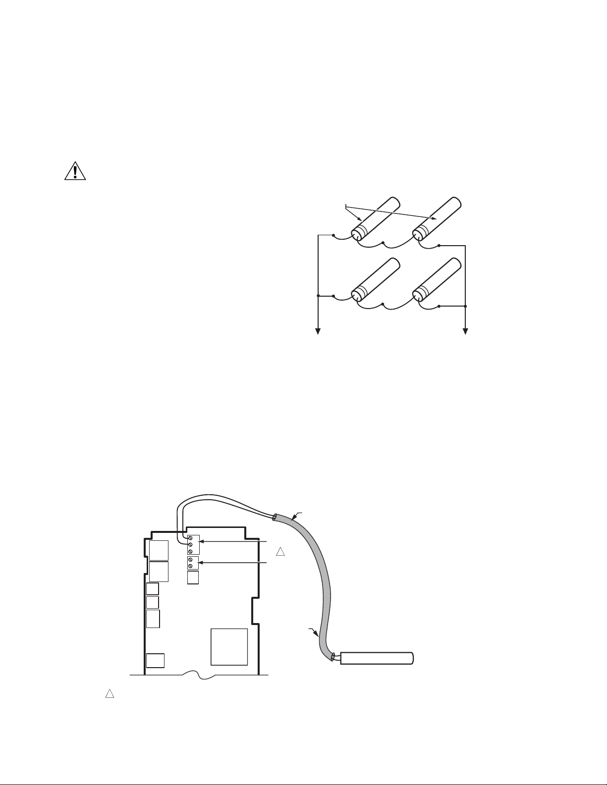
The linear platinum temperature sensor and
thermowell mount into the piping between the
outlet manifold of the aftercooler and the
separator. When the temperature of the compressed air system at the aftercooler outlet falls
to 35OF, the controller will automatically turn off of
the fan. The controller is set for a 10oF dead
band to prevent rapid cycling (fan will turn off at
35OF and on at 45oF).
A 12 foot heat tape and 30 feet of insulation wrap
are provided to wrap around the separator. The
heat tape is equipped with its own internal
temperature control. The heat tape and insulation will provide additional freeze up protection.
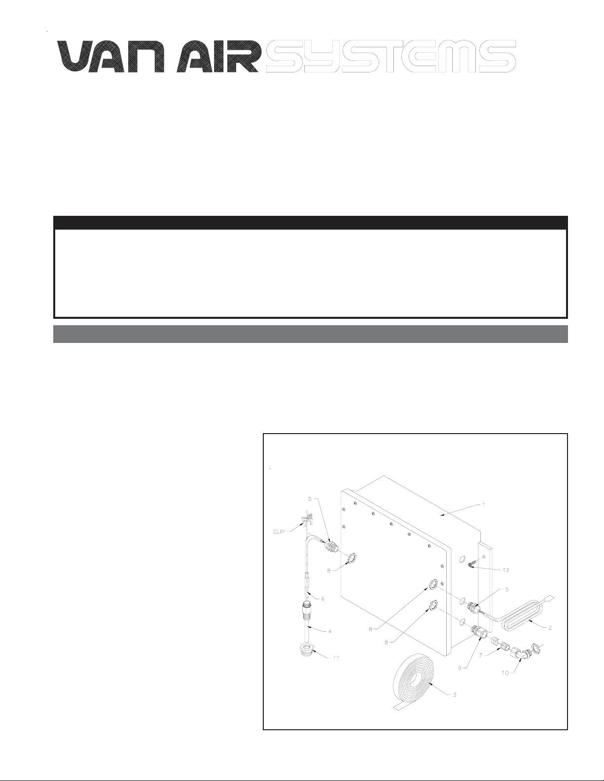
1.2 THIS KIT INCLUDES:
Control box
1.
12' long heat tape, w/ thermostat
2.
30' long roll of insulation wrap
3.
Copper 1/2" NPT thermowell w/clip
4.
Cord grip connector
5.
Linear platinum sensor
6.
2' of 3/8" flexible conduit
7.
Three (3) seal fittings for connectors
8.
3/8" conduit straight connector
9.
3/8" 90 degree elbow connector
10.
1" x 1/2" NPT bushing
11.
Four (4) #12-14 x 1" self tapping screws
12.
Heat Condictive Compound
13.
FIGURE 1-A ITEMS INCLUDED WITH THIS KIT
PAGE 1
Page 2
SECTION 2 INSTALLATION
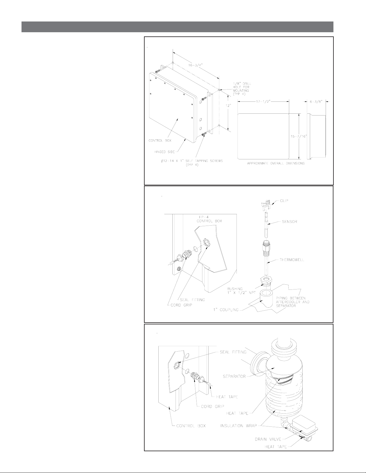
2.1 MOUNTING THE CONTROL BOX
The control box should be mounted near the
outlet manifold of the aftercooler. Make sure
that the control box is close enough so that all
components can reach the box when installed.
Drill the four pilot holes in the mounting
surface using a 1/8" drill. Reference Figure 2A for dimensions.
The control box will be mounted with the
hinged side of the enclosure on the bottom.
Fasten the controller in place using the four
(4) #12-14 x 1" long self-tapping screws
supplied with the kit.
2.2 INSTALLING THE SENSOR AND
THERMOWELL
A 1/2" NPT or larger connection in the system
piping between the outlet of the aftercooler
and the inlet of the separator is required for
the thermowell and sensor.
Thread the thermowell and the 1" x 1/2"
bushing (if required) into a connection
between the aftercooler outlet and the
separator.
FIGURE 2-A MOUNTING THE CONTROL BOX
FIGURE 2-B MOUNTING THE THERMOWELL
Place some heat conductive compound into
the thermowell. Place the sensor into the
thermowell and fasten it in place using the
clip supplied with the thermowell. Reference
Figure 2-B.
Install the cord grip connector into the control
box as shown in Figure 2-B. Push the sensor
cable through the connector. Wire the sensor
cable to the controller circuit board terminals
as shown in Figure 2-F. Tighten the grip nut
on the connector.
2.3 INSTALLING THE HEAT TAPE AND
INSULATION
Install the cord grip on the control box as
shown in Figure 2-C.
Cut the plug end off the heat tape. Strip back
the wires.
Push the wire end of the heat tape through
the connector. Allow enough cord inside the
box for wiring. Connect the heat tape to the
proper terminals in the control box as shown
in FIGURES 2-F. Tighten the grip nut on the
connector.
FIGURE 2-C INSTALLING THE HEAT TAPE AND INSULATION
Run the heat tape to the separator. Wrap the
heat tape around the separator as shown in
Figure 2-C. Do not overlap the tape.
Wrap the insulation around the piping and
heat tape as shown in Figure 2-C.
PAGE 2
Page 3
SECTION 2 INSTALLATION
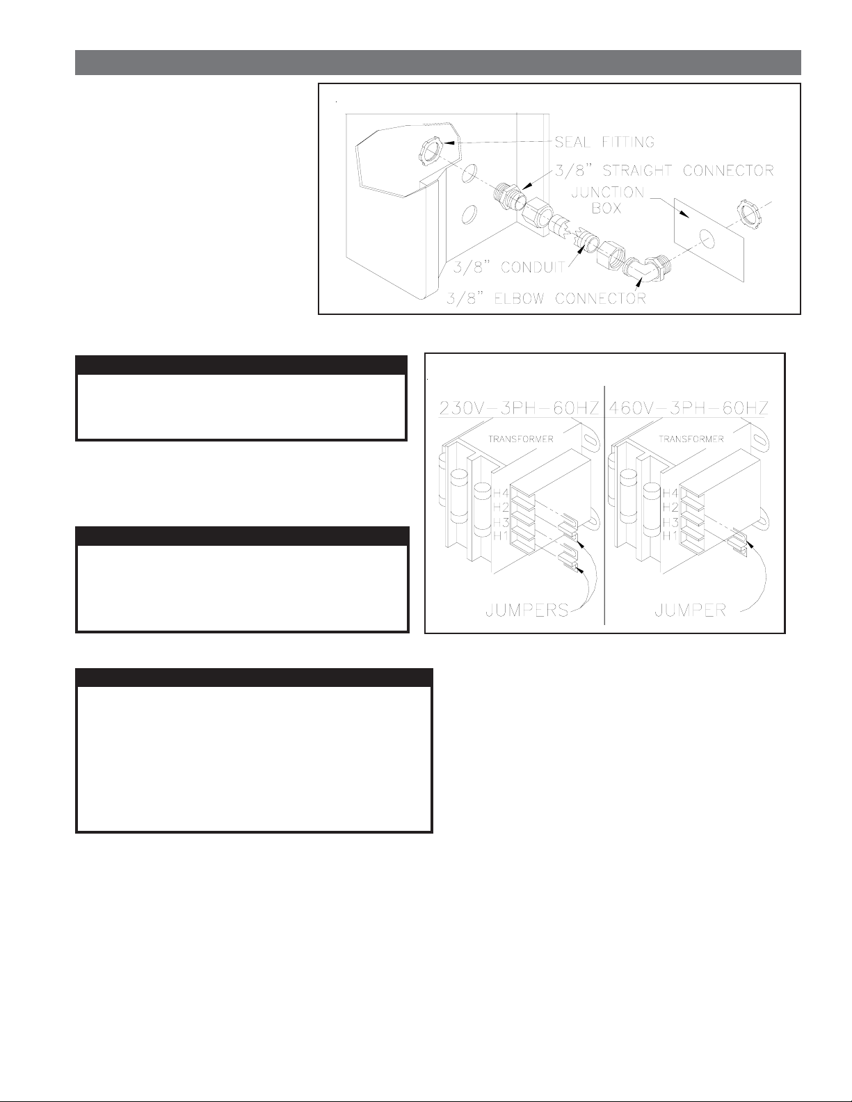
2.4 INSTALLING THE CONDUIT
Install the straight conduit connector
on the control box. Reference Figure
2-D.
The supplied conduit will be used to
run between the aftercooler and the
control box. Connect the conduit to
the straight connector.
Install the 90 degree elbow connector
on the aftercooler. Reference Figure
2-D.
FIGURE 2-D INSTALLING THE CONDUIT
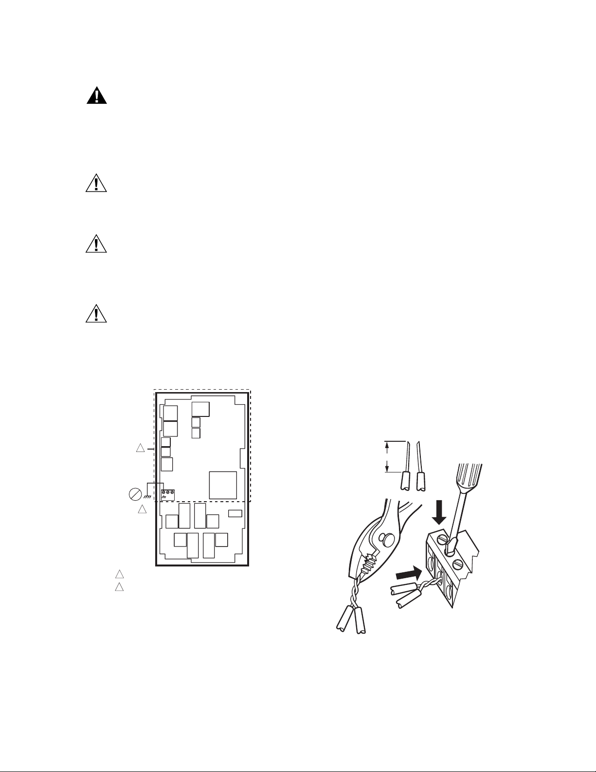
2.5 INSTALLING THE TRANSFORMER JUMPERS
WARNING
BEFORE STARTING THIS PROCEDURE, TURN OFF
ELECTRICAL POWER. FAILURE TO HEED THIS
WARNING MAY RESULT IN SERIOUS PERSONAL
INJURY AND/OR DAMAGE TO THE UNIT.
This kit was designed to operate at 230V-3PH-60Hz or
460V-3PH-60Hz. Two jumpers were shipped inside the
control box. They must be installed on the transformer
before connecting the power to the control box. Install the
jumper(s) as shown in Figure 2-E for the desired voltage.
CAUTION
It is important that this procedure be properly
completed before continuing with installation.
This kit will not operate without the jumpers.
Damage to the control box will occur if the jumpers
are improperly installed.
FIGURE 2-E INSTALLING THE TRANSFORMER JUMPERS
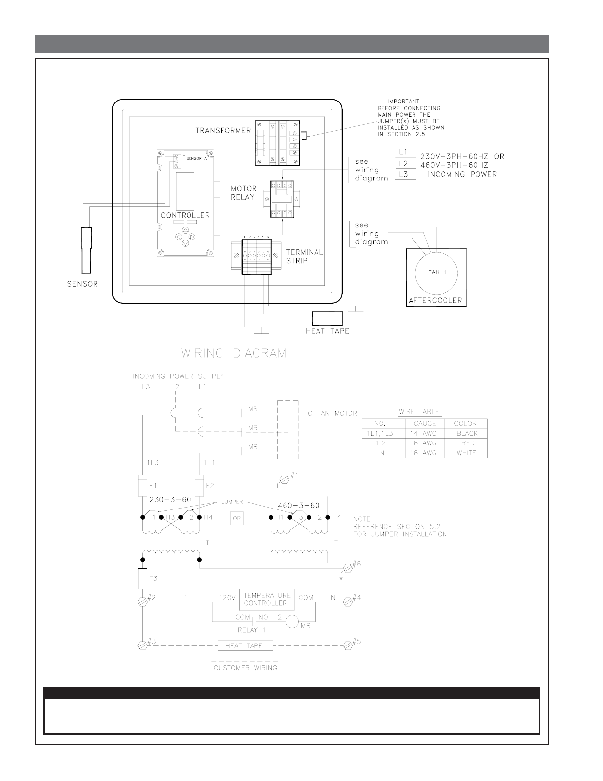
2.6 ELECTRICAL CONNECTIONS
WARNING
BEFORE STARTING INSTALLATION PROCEDURES
OR ATTEMPTING TO MAKE ANY WIRING CHANGES,
TURN OFF ELECTRICAL POWER. FAILURE TO HEED
THIS WARNING MAY RESULT IN SERIOUS
PERSONAL INJURY AND/OR DAMAGE TO THE UNIT.
WHEN INSTALLING THIS KIT ALWAYS COMPLY WITH
THE NATIONAL ELECTRICAL CODE AND ALL OTHER
APPLICABLE FEDERAL, STATE AND LOCAL CODES.
A 7/8" hole in the top right side of the control box is provided
for incoming power conduit. The hole can be enlarged if
necessary.
The control box is designed for 230V-3PH-60Hz or 460V3PH-60Hz operation. The transformer jumpers must be
installed as outlined in Section 2.5 for the desired voltage.
Make the necessary wiring runs and connections for the
main power supply.
Remove the junction box cover on the aftercooler for access
to the junction box. Make the necessary wiring runs through
the conduit from the aftercooler to the control box. Fasten the
conduit to the connector on the aftercooler. Reference
FIGURE 2-D.
Make the wire connections at the junction box on the
aftercooler. Reference FIGURE 2-F. Fasten the junction box
cover to the aftercooler.
Complete the wire connections inside the controller as
shown in FIGURE 2-F.
Once all wiring connections have been properly made, the
rotation of the fan should be checked. The fan must rotate in
the proper direction for maximum performance. Reference
the operator's manual supplied with the aftercooler for the
correct rotation direction. Also, check the aftercooler for a
rotation direction label.
To check the rotation, turn on the power supply to the
aftercooler. If the fan does not rotate in the proper direction,
any two of the power leads to the motor can be switched.
PAGE 3
Page 4
SECTION 2 INSTALLATION
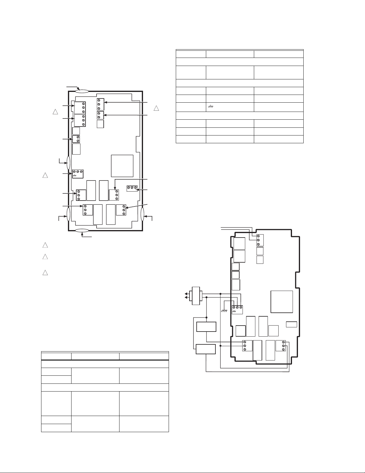
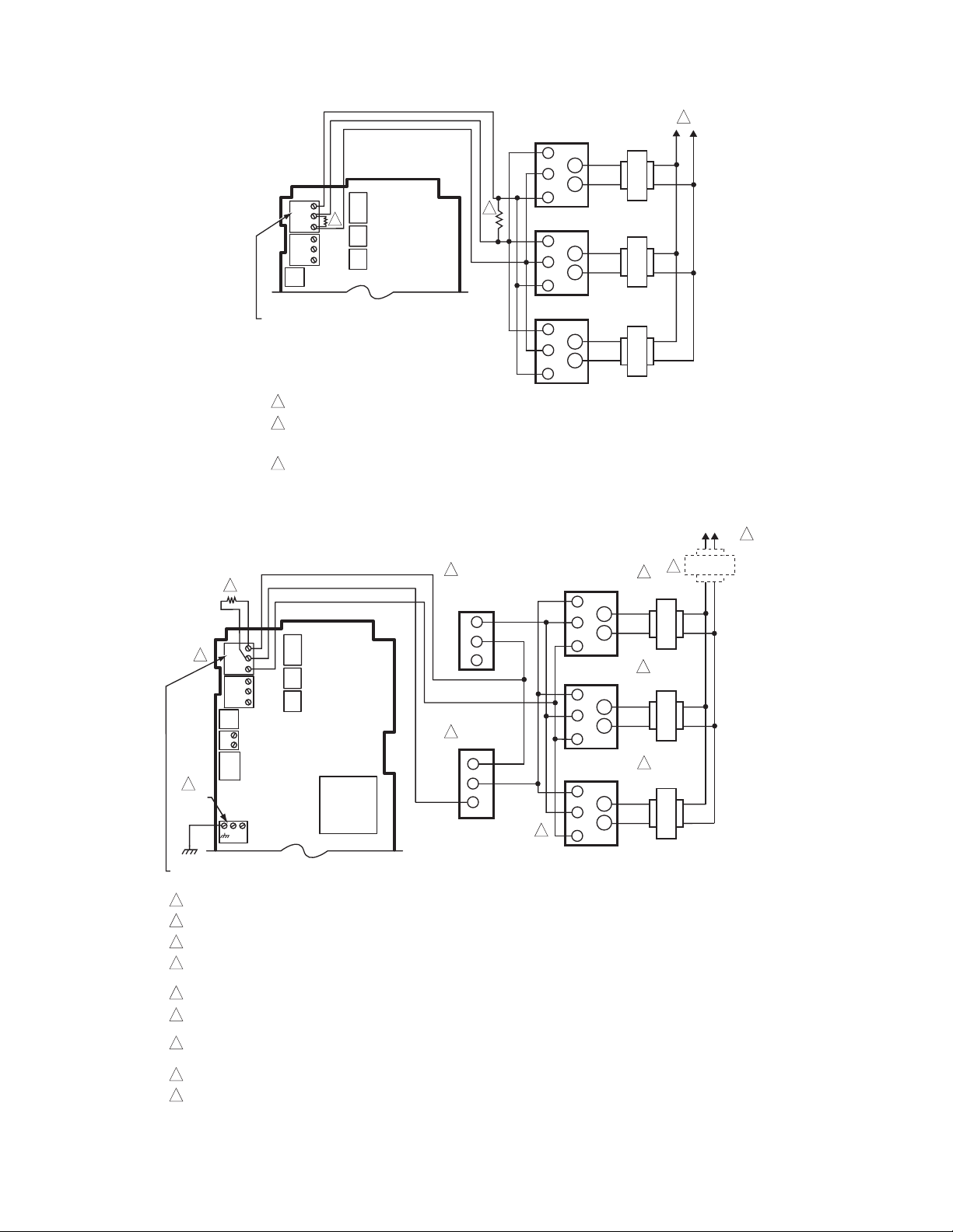
FIGURE 2-F CONTROL BOX COMPONENT LAYOUT and WIRING DIAGRAM
IMPORTANT
THE FAN MOTOR MUST ROTATE IN THE CORRECT DIRECTION. REFERENCE THE AFTERCOOLER
OPERATOR'S MANUAL FOR PROPER ROATION DIRECTION. IF IT DOES NOT, THE ROTATION CAN BE
CORRECTED BY SWITCHING TWO OF THE POWER LEADS TO THE MOTOR.
PAGE 4
Page 5
SECTION 2 INSTALLATION
2.7 SETTING THE CONTROLLER
The controller was factory set for normal operation. The
factory settings are as follows:
RELAY 1
O
SET POINT 35
DIFFERENTIAL 10
MODE COOLING
Turn on the main power to the FP-4 control.
If the settings have been changed, set them to the factory
settings following the procedures below . The controller will
retain the setting if the power is disconnected.
PROGRAMMING PROCEDURES
1. Press MENU key, then press RIGHT arrow key three
times. Use the UP and DOWN arrow to select the
SETPOINT. Press the RIGHT arrow to store the setpoint in
memory.
2. Press the RIGHT arrow to set the DIFFERENTIAL. Use
the UP and DOWN arrow to set the differential. Press the
RIGHT arrow to store the differential in memory.
3. Press the RIGHT arrow key to set the HEATING / COOL-
ING mode. Use the UP or DOWN arrow to select the
desired mode. Press the RIGHT arrow to store the mode in
memory.
F
O
F
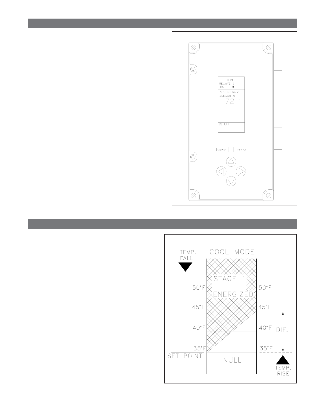
FIGURE 2-G CONTROLLER DISPLAY
4. Press RIGHT arrow three times to exit the program mode.
SECTION 3 OPERATION
3.1 OPERATION
Once the kit is installed and set properly, just energize the
controller and it will operate automatically.
The controller will turn off half of the aftercooler fan when the
temperature of system air at the outlet of the aftercooler falls
to 35OF. The fan will turn on when the system temperature
rises to 45oF. Reference chart in Figure 3-A .
The heat tape is controlled by its own internal thermostat.
Power is supplied to the heat tape as long as the control box
is energized.
The temperature controller is equipped with a LCD display.
During normal operation when the fan are operating,
(temperature above set points) the sensor temperature and
RELAYS 1 ON will be displayed on the controller.
NOTE: The cover on the control box must be opened to view
the temperature controller display.
FIGURE 3-A OPERATION SEQUENCE
PAGE 5
Page 6

SECTION 4 TROUBLESHOOTING
4.1 TROUBLESHOOTING PROCEDURES
PROBLEM POSSIBLE CAUSES
1. Aftercooler fan motor
continues to operate,
system temperature
below 35
O
F.
Controller not set properly
Control relay faulty
Check the controller settings as outlined in Section 2.7. The
controller may be set in the heat mode or the set points set too
low. Set the controller to the recommended settings.
Check the control relay. Replace if faulty.
SOLUTIONS
2. Aftercooler fan motor
not operating, system
temperature above
45OF.
No power to the control box
No power to the controller
Controller not set properly
Controller failure
Sensor failure
Control relay faulty
Check main electrical power source.
Check the transformer. Make sure that the jumpers on the
transformer are properly installed. Reference Section 2.5.
Check the fuses on the transformer.
Check the controller settings as outlined in Section 2.7. The
controller may be set in the heat mode or the set points set too
high. Set the controller to the recommended settings.
Check the controller settings. If the controller is properly set, check
the main power source.
Check the controller display for error codes. Section 4.2 outlines
what the error codes indicate and the necessary steps.
If the sensor is faulty a "--" will be displayed for the temperature on the
controller display. Refer to Section 4.2 for further details. If the
sensor is faulty, it must be replaced.
Check the control power at the relay coil. Check the relay for proper
operation. Replace if faulty.
4.2 CONTROLLER ERROR CODES
The controller display panel is used to display error codes in the event of problems with the controller. The four error codes
are listed below.
-- -SENSOR FAILURE
The "--" displayed for the temperature indicates that there is a problem with the sensor. The sensor is open or shorted.
All relays will be de-energized in the event of a sensor failure. If the sensor is damaged, it must be replaced.
EE-EEPROM FAILURE
The "EE" error code indicates that there is a problem with EEPROM. The values read back from the EEPROM are not
the same as what was written into the EEPROM. This error cannot be field repaired. The controller must be replaced.
-60°F or 270°F (-51°C or 132°C) Blinking - TEMPERATURE OUT OF RANGE
The temperature display blinks when the sensed temperature is outside of the display range, below -60°F (-51°C) or
above 270°F (132°C). The displayed value remains at the display limit and the controller continues to function unless
an open or shorted condition is detected.
BLINKING RELAY STATUS
This occurs when the Relay Minimum Off Time is active. The (ñ ) blinks while the relay's minimum off time is active.
PAGE 6
Page 7
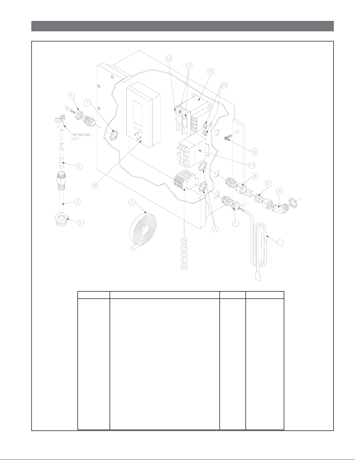
SECTION 5 REPLACEMENT PARTS
5.1 REPLACEMENT PARTS
ITEM NO.
1
2
3
4
5
6
7
8
9
11
12
13
14
15
16
17
18
19
20
21
22
23
DESCRIPTION
12' LONG HEAT TAPE
30' ROLL OF INSULATION WRAP
1/2" NPT THERMOWELL w/CLIP
CORD GRIP CONNECTOR
SENSOR
3/8" FLEXIBLE CONDUIT
SEAL FITTING FOR CONNECTOR
3/8" CONDUIT STRAIGHT CONNECTOR
3/8" 90O ELBOW CONDUIT CONNECTOR
1" X 1/2" NPT BUSHING
#12-14 x 1" SELF TAPPING SCREW
TEMPERATURE CONTROLLER
MOTOR RELAY
TRANSFORMER
1 AMP FUSE
.6 AMP FUSE
GRAY TERMINAL
YELLOW TERMINAL
GREEN TERMINAL
END CLAMP TERMINAL
JUMPER FOR TERMINAL
JUMPER FOR TRANSFORMER
QTY
1
1
1
2
1
2 FT
3
1
1
1
4
1
1
1
1
2
2
2
2
2
2
2
PART NO.
26-8151
26-0712
29-0325
26-5618
26-7186
26-0875
26-0883
26-1068
26-1078
14-0402
28-1286
26-7185
26-0919
26-5637
26-5336
26-5638
26-0380
26-0382
26-0384
26-0388
26-0686
26-5663
PAGE 7
Page 8

SECTION 6 WARRANTY
PER VAN AIR TERMS AND CONDITIONS OF SALE
PAGE 8
YOUR VAN AIR REPRESENTATIVE IS:
NAME:
COMPANY:
ADDRESS:
CITY: STATE: ZIP:
PHONE: FAX:
ATTACH BUSINESS CARD HERE
MAKING COMPRESSED AIR AND GAS WORK BETTER SINCE 1944.
2950 Mechanic Street
Lake City, PA 16423 USA
Phone: 800/840-9906
Service Fax: 814/774-0778
Order Entry Fax: 814/774-3482
www.vanairsystems.com
Page 9
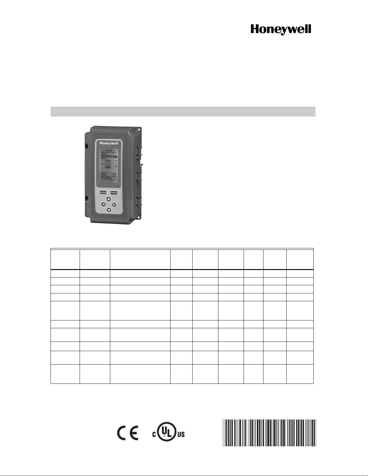
T775A/B/M Series 2000 Electronic
Stand-Alone Controllers
INSTALLATION INSTRUCTIONS
PRODUCT DESCRIPTION
The T775 electronic stand-alone controllers are the next
generation of commercial and agricultural controls
capable of remote sensing of temperature and providing
switched and/or proportional outputs to various types of
loads.
Five models have analog (modulating) outputs for
actuator and motor control, and NEMA-4 weatherproof
enclosures are available for wet environments.
IMPORTANT
Each T775A/B/M controller is an operating
control, not a limit or safety control. If used in
applications requiring safety or limit controls, a
separate safety or limit control device is
required.
Table 1. T775A/B/M Controller Configurations.
Controller
T775A2009 Standard T775A1001 1 None None 1 1 NEMA 1
T775B2016 Standard N/A 2 None 1 2 1 NEMA 4X
T775B2024 Standard T775C1009 T775D1008 4 None 2 2 1 NEMA 4X
T775B2032 Standard T775A1019 T775B1000 2 None 1 2 1 NEMA 1
T775B2040 Standard T775A1027 T775A1035
T775M2006 Modulating N/A None 2 N/A 2 1 NEMA 1
T775M2014 Modulating T775G1005 T775G1013
T775M2022 Modulating N/A 2 2 N/A
T775M2030 Modulating T775E1114 T775F1022
T775M2048 Modulating T775E1015 T775E1023
a
b
c
d
a
Model
All models include a digital input for use with the disable or setback option.
The modulating (analog) outputs are 4-20 mA, 0-10 Vdc, 2-10 Vdc, or Series 90 selectable.
Each floating output eliminates two SPDT relays.
These models can support a high/low modulating limit at Sensor B for temperature control at Sensor A.
Description Replaces
T775B1018 T775B1026
T775B1042
T775G1021 T775G1039
T775F1055 T775F1089
T775E1056 T775E1064
T775E1098
SPDT
Relay
Outputs
Analog
(Mod)
Outputs
4None 2 2 1NEMA 1
42N/A
42N/A
22N/A
Floating
b
Outputs
Sensor
c
Inputs
Nbr of
Sensors
Included Enclosure
d
2
d
2
d
2
d
2
1 NEMA 4X
1 NEMA 4X
1 NEMA 1
1 NEMA 1
E4436
62-0254-03
Page 10
T775A/B/M SERIES 2000 CONTROLLER PRODUCT DESCRIPTION
Temperature Sensors
a
The controller accepts 1,097 Ohms PTC at 77°F (25°C):
• 50021579-001 – Standard sensor (included with all
models except NEMA 4X models)
• T775-SENS-WR – Water resistant with 5 foot leads
(included with NEMA 4X models)
• T775-SENS-WT – Watertight with 6 foot lead
• T775-SENS-OAT – Outdoor air temperature sensor
• C7031D2003 – 5 inch immersion sensor with wiring
box (use immersion well; P/N 50001774-001)
• C7031J2009 – 12 foot duct averaging sensor with
wiring box
• C7046D1008 – 8 inch duct probe with mounting flange
• C7100D1001 – 12 inch fast response, duct averaging
sensor with flange
• C7130B1009 – Room mount sensor
a
See form 62-0265 – Temperature Sensors for the T775
Series 2000 Stand-alone Controller
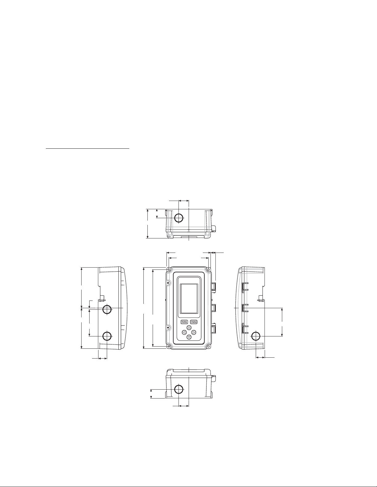
Controller Dimensions
1 (25.5)
7/8 (22.5)
2 15/16 (74)
Accessories
• 107324A – Bulb Holder, duct insertion
• 107408 – Heat Conductive Compound, 4 ounce
• 50001774-001 – Immersion Well, stainless steel 304,
1/2 in. threading
TOP
4 1/16 (103.4)
4 1/16 (103.4)
7/8 (22.5)
1/64 (3.8)
2 11/16 (68.1)
4 13/32 (112.1)
LEFT RIGHT
8 5/32
(207.1)
7 23/32
(196)
7/8 (22.5)
1 (25.5)
3 31/32 (101)
FRONT VIEW
BOTTOM
1/2 (12.4)
Fig. 1. T775A/B/M dimensions in inches (mm).
2 13/16 (71.8)
7/8 (22.5)
M24279
62-0254–03 2
Page 11

BEFORE INSTALLATION T775A/B/M SERIES 2000 CONTROLLER
BEFORE INSTALLATION
Review the “Specifications” on page 35 before
installing the controller.
When Installing This Product
1. Read these instructions carefully. Failure to follow
them could damage the product or cause a hazardous condition.
2. Check ratings given in instructions and on the prod-
uct to ensure the product is suitable for your application.
3. Installer must be a trained, experienced service
technician.
4. After installation is complete, check out product
operation as provided in these instructions.
INSTALLATION AND SETUP
The following installation procedures are typically
performed in the order listed:
1. Mounting — see “Mounting” below.
2. Wiring — see “Wiring” on this page.
3. Checkout — see page 10.
4. Programming — see page 13.
5. Scheduling (optional) — see page 30.
Additional topics are:
• Temperature sensor calibration begins on page 10.
• Interface overview begins on page 11.
• Setup (for advanced options) begins on page 17.
• Summary menu begins on page 34.
• Troubleshooting begins on page 34.
MOUNTING
This section describes the mounting procedures for the
controller and temperature sensor(s).
The controller may be mounted in any orientation.
However, mounting in the orientation shown in Fig. 1
permits proper viewing of the LCD display and use of the
keypad.
NEMA 4 Enclosure Mounting
For models with NEMA 4 enclosures, ensure that
waterproof wire/conduit fittings are used at the knockouts
for all wiring attachments. See Fig. 7 on page 6 for
knockout locations.
IMPORTANT
For NEMA 4 enclosures, be sure to cover and
seal all unused open knockouts.
Temperature Sensor(s) Mounting and
Location
Temperature sensors may be located up to 1,000 feet
(304 m) from the T775A/B/M controller. See Table 3 on
page 10 for calibration guidelines.
The sensors may be mounted on a wall or panel for
sensing space temperature, strapped to a pipe or inserted
in an immersion well (see Fig. 2) for hot or cold water
sensing, or taped to a standard cap or bulb holder for duct
air sensing. To prevent moisture or condensation entering
the sensor through the lead wire holes, mount the sensor
with the lead wires exiting the bottom of the sensor.
NOTES:
1. The included sensor is not designed for very
wet applications. For immersion applications,
an immersion well is used.
2. Heat conductive compound must be used in
immersion wells.
3. See “Temperature Sensors” on page 2 for this
type of installation.
SENSOR
PLACED
IN WELL
USE HEAT
CONDUCTIVE
COMPOUND
Controller Mounting
IMPORTANT
Avoid mounting in areas where acid fumes or
other deteriorating vapors can attack the metal
parts of the controller circuit board, or in areas
where escaping gas or other explosive vapors
are present.
IMPORTANT
The controller must be mounted in a position that
allows clearance for wiring, servicing, and
removal.
Use a screwdriver to pry out only the knockouts that you
will use.
If mounting on DIN rail, be sure to remove the knockouts
before mounting. See “Controller Wiring” on page 5 and
Fig. 7 on page 6 for recommended knockout usage and
locations. If you do not use an opened knockout be sure
to cover it.
Mount the controller on any convenient interior location
using the four mounting holes provided on the back of the
enclosure using #6 or #8 screws (screws are not provided
and must be obtained separately). Use controller
dimensions in Fig. 1 on page 2 as a guide.
1/2 NPT
Fig. 2. Sensor inserted in immersion well.
NOTE: Multiple sensors may be parallel-series wired to
sense average temperatures in large spaces.
See Fig. 3 on page 4.
IMMERSION
WELL
M24470
WIRING
All wiring must comply with applicable electrical codes
and ordinances, or as specified on installation wiring
diagrams. Controller wiring is terminated to the screw
terminal blocks located inside the device.
The remainder of this section describes the temperature
sensor wiring and the T775A/B/M controller wiring.
3 62-0254–03
Page 12
T775A/B/M SERIES 2000 CONTROLLER WIRING
Wiring Connections Access
To access the wiring connections, remove the two screws
on the left side of the enclosure and gently swing open the
top. Be careful to not stress the ribbon cables that
connect the keypad and LCD display to the controller
circuit board.
Temperature Sensor Wiring
CAUTION
Electrical Shock Hazard.
Can short equipment circuitry.
Make sure that metal tube of sensor does not
short against T terminals in wall-mounted case.
IMPORTANT
Poor wiring practices can cause erratic readings
from the sensor. Avoid the following to ensure
proper operation:
• Do not route the temperature sensor wiring with
building power wiring.
• Do not locate the temperature sensor wiring next
to control contactors.
• Do not locate the temperature sensor wiring near
electrical motors.
• Do not locate the temperature sensor wiring near
welding equipment.
• Make sure good mechanical connections are
made to both the sensor and the controller.
• Do not mount the sensor with the lead wire end
pointing up in an area where condensation can
occur.
If any of the above conditions cannot be
avoided, use shielded cable.
NOTE: Each T775 controller must be wired to its own
sensor(s). However, a benefit of the T775
controller’s accuracy is that there is no more
than a 2°F differential between any two T775
controllers.
Multiple Parallel Sensors
Multiple sensors can be parallel-series wired to sense
average temperatures in large spaces. To maintain
control accuracy, the number of sensors to be parallelseries wired must be of the n
2
power (for example, 4, 9,
16, etc.). See Fig. 3.
SENSORS
TO T775 CONNECTIONS (SENSOR A) OR (SENSOR B).
M24471
Fig. 3. Parallel-series wiring of sensors.
Temperature Sensor Wire Type and Size
Temperature sensors use standard AWG 18/2 unshielded
wire. For cable runs greater than 25 feet or where
electrical interference may be a problem, shielded cable
is recommended. See Fig. 4.
Refer to “Temperature Sensor Calibration” on page 10 for
wire size selection where cable runs are longer than 25
feet.
T
T
T
T
SENSOR A AND SENSOR B TERMINAL WIRING IS POLARITY INSENSITIVE.
1
SENSOR A
1
SENSOR B
SHIELDED
CABLE
Fig. 4. Sensor wiring — showing shielded cable connection to Sensor A.
SHIELDED
CABLE
NOTE: SHIELDED CABLE MUST BE
CONNECTED TO AN EARTH
GROUND.
HOWEVER, DO NOT GROUND
SHIELDED CABLE AT SENSOR END.
SENSOR
NOTE: TO MINIMIZE NOISE PICKUP,
MAKE SENSOR CONNECTION FROM
SHIELDED CABLE AS CLOSE AS
POSSIBLE TO SENSOR BODY.
M24472
62-0254–03 4
Page 13
WIRING T775A/B/M SERIES 2000 CONTROLLER
Controller Wiring
WARNING
Electrical Shock Hazard.
Can cause severe injury, death or property
damage.
Disconnect power supply before beginning wiring,
or making wiring connections, to prevent electrical
shock or equipment damage.
CAUTION
Do not use 24 Vac power to power any external
loads if 120 Vac or 240 Vac is used to power
the T775A/B/M controller.
CAUTION
A separate earth ground is required.
Equipment damage can result if the earth ground
is not connected. See Fig. 5 and Table 2 on
page 6.
CAUTION
Equipment Damage Hazard.
Electrostatic discharge can short equipment
circuitry.
Ensure that you are properly grounded before
handling the unit.
See Fig. 7 on page 6 for locating the appropriate power
input, remote sensors input, low voltage, contact closure,
and load output terminals.
Access to the terminals can be gained through standard
conduit knockouts (A through E in Fig. 7 on page 6)
located around the perimeter of the enclosure:
• Knockouts A and B should be used only for sensor and
low-voltage wiring.
• Knockouts C, D, and E can be used to gain access to
the load relay output terminals and 120/240 Vac power
wiring.
Controller Wiring Method
Wire the sensors and outputs, then wire the power
connection.
Each terminal can accommodate the following gauges of
wire:
• Single wire – from 14 AWG to 22 AWG solid or
stranded
• Multiple wires – up to two 22 AWG stranded
For 24, 120, or 240 Vac power connections:
Single wire – from 14 to 18 AWG solid or stranded
Prepare wiring for the terminal blocks, as follows:
1. Strip 1/2 in. (13 mm) insulation from the conductor.
2. Cut a single wire to 3/16 in. (5 mm). Insert the wire
in the required terminal location and tighten the
screw.
3. If two or more wires are being inserted into one ter-
minal location, twist the wires together a minimum
of three turns before inserting them to ensure
proper electrical contact.
4. Cut the twisted end of the wires to 3/16 in. (5 mm)
before inserting them into the terminal and tightening the screw.
5. Pull on each wire in all terminals to check for good
mechanical connection.
1
2
IMPORTANT
Poor wiring practices can cause erratic readings
from the sensor. To ensure proper operation,
ensure that good mechanical connections are
made to both the sensor and the controller.
IMPORTANT
When wiring the input power, only one source of
power can be applied to the T775A/B/M controller (24 Vac or 120 Vac or 240 Vac).
1
W
NO HIGH VOLTAGE. CLASS 2 WIRING ONLY.
EARTH GROUND TERMINAL MUST BE CONNECTED
TO CONDUIT CLAMP LOCALLY.
C
+
2
M24296
Fig. 5. Earth Ground.
1. STRIP 1/2 IN. (13 MM)
FROM WIRES TO
BE ATTACHED AT
ONE TERMINAL.
2. TWIST WIRES
TOGETHER WITH
PLIERS (A MINIMUM
OF THREE TURNS).
1/2 (13)
3. CUT TWISTED END OF WIRES
TO 3/16 IN. (5 MM) BEFORE INSERTING
INTO TERMINAL AND TIGHTENING SCREW.
THEN PULL ON EACH WIRE IN ALL
TERMINALS TO CHECK FOR
GOOD MECHANICAL CONNECTION.
M24473
Fig. 6. Attaching two or more wires at terminal blocks.
5 62-0254–03
Page 14
T775A/B/M SERIES 2000 CONTROLLER WIRING APPLICATIONS (EXAMPLES)
Controller Wiring Details
The wiring connection terminals are shown in Fig. 7 and
are described in Table 2.
See Fig. 8 – Fig. 20 beginning on page 6 for typical
T775A/B/M wiring applications.
KNOCKOUT A
NO
C
NC
KNOCKOUT E
T
T
T
T
NC
C
NO
120
NO
C
NC
MOD 1
2
MOD 2
DIGITAL
INPUT
KNOCKOUT B
POWER
3
24 VAC
OUTPUT
RELAY 4
OUTPUT
RELAY 1
KNOCKOUT C
1
SENSORS A AND B USE THE TWO TT CONNECTIONS AND ARE
POLARITY INSENSITIVE.
2
FOR MOD 1 AND MOD 2 CURRENT (mA) OR VOLTAGE (VDC) OUTPUT,
USE SIGNAL (+) & COMMON (-).
FOR MOD 1 AND MOD 2 SERIES 90 OUTPUT, USE W, R, & B.
A SEPARATE EARTH GROUND IS REQUIRED FOR ANY POWER
3
SOURCE (24, 120, OR 240 VAC).
B
–
R
+
W
B
–
R
+
W
–
+
C
+
NC
C
NO
Fig. 7. T775A/B/M terminal and feature locations.
NOTE: Refer to Table 1 on page 1 for the specific con-
figuration of sensors and outputs supported by
the model you are installing.
NOTE: For NEMA 4 enclosures, use waterproof fittings
for wiring/conduit connections at knockouts.
COM
240
SENSOR A
1
SENSOR B
OUTPUT
RELAY 3
POWER
120/240 VAC
OUTPUT
RELAY 2
KNOCKOUT D
M24474
Table 2. Description of Wiring
Terminal Connections. (Continued)
Connection Terminal Label Description
Input
DI + - Digital Input (dry
contact)
24 Vac Power
24V + + 24 Vac Hot
Common C 24 Vac Common
Ground
Earth Ground
b
120 or 240 Vac Power
120 Vac 120 120 Vac Power
Common COM Common
240 Vac 240 240 Vac Power
a
For Series 90 connections, you must insert a 340 Ohm
resistor across terminals R and W. See Fig. 17 on
page 8. The resistor is included with the controller.
b
A separate earth ground is required for all installations
regardless of the power source (24, 120, or 240 Vac).
See Fig. 5 on page 5.
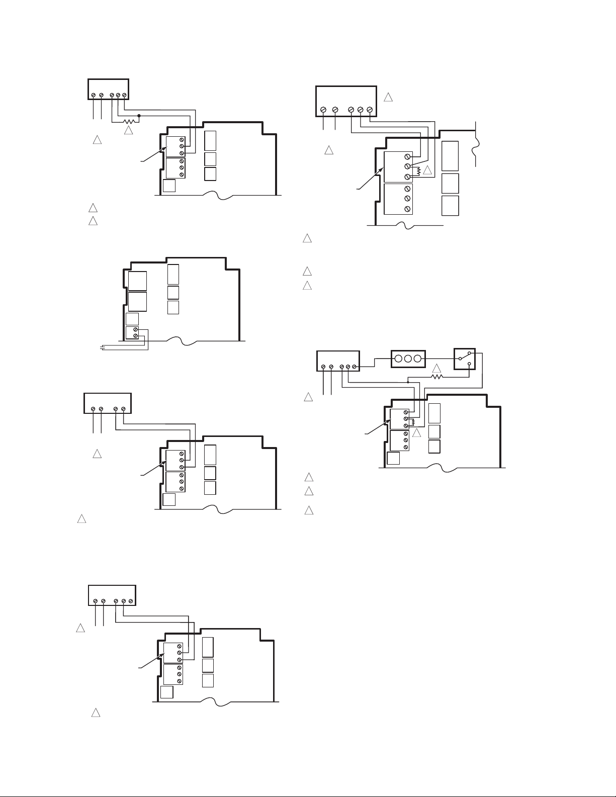
WIRING APPLICATIONS
(EXAMPLES)
Fig. 8 – 20 illustrate typical controller wiring for various
applications.
SENSOR A
T
T
L1
(HOT)
L2
24 VAC
LOAD 1
C
+
Table 2. Description of Wiring
Terminal Connections.
Connection Terminal Label Description
Sensors
Sensor A
Sensor B
T T
Outputs
Temperature Sensor;
polarity insensitive
Fig. 8. Wiring for two-stage control – 24 Vac input and
Relay 1
Relay 2
Relay 3
Relay 4
Mod 1
Mod 2
62-0254–03 6
NO
COM
NC
+ - (Vdc or mA)
W R B (Series 90)
120-240 Vac Relay
Output
Modulating Output
a
LOAD 2
NO
COM
24 Vac load.
NO
C
NC
NO
C
NC
COM
NO
M24475A
Page 15

WIRING APPLICATIONS (EXAMPLES) T775A/B/M SERIES 2000 CONTROLLER
A
SENSOR A
T
T
L1
(HOT)
24 VAC
L2
C
+
LOAD
4
LOAD
1
LOAD
2
LOAD
3
COM
NO
NO
COM
COM
NO
COM
NO
NC
C
NO
NO
C
NC
NC
C
NO
NO
C
NC
Fig. 9. Wiring for four-stage control – 24 Vac input
and 24 Vac load.
M24476
SENSOR A
T
T
C
COM
NO
NO
COM
+
NC
C
NO
NO
C
NC
NC
C
NO
NO
C
NC
120
COM
240
120V
COM
1
LOAD
3
LOAD
2
LOAD 1
LOAD 4
FOR 240 VAC LOAD, CO NNECT TO 240 TER MINAL .
1
M24478A
Fig. 11. Wiring for four-stage control with 120 or 240
Vac (120 Vac input and 120 Vac load shown).
SENSOR A
T
T
C
NO
COM
+
1
NO
C
NC
NO
C
NC
120
NO
COM
COM
120V
COM
POWER SUPPLY
240
LOAD 2
L1 ( HOT )
L2
LOAD 1
FOR 240 VAC LOAD, CO NNECT TO 240 TER MINAL .
1
M24477A
Fig. 10. Wiring for two-stage control with 120 or 240
Vac (120 Vac input and 120 Vac load shown).
120/240 VAC LINE
1
1
2
NO
C
NC
BARCODE
CLOSE RELAY TO DRIVE DEVICE OPEN. RELAY 1 SHOWN.
(RELAYS 1 AND 3 ARE USED FOR OPEN).
CLOSE RELAY TO DRIVE DEVICE CLOSED. RELAY 2 SHOWN.
(RELAYS 2 AND 4 ARE USED FOR CLOSE).
THE RELAYS MUST BE WIRED IN PAIRS WITH RELAYS 1 AND 2
BEING THE FIRST PAIR, AND RELAYS 3 AND 4 BEING THE SECOND PAIR.
NO
C
NC
2
NO
COM
COM
NO
DEVICE
OPEN
COM
CLOSE
M24479
Fig. 12. Wiring for floating output (Relay 1 and Relay 2
pair shown).
7 62-0254–03
Page 16
T775A/B/M SERIES 2000 CONTROLLER WIRING APPLICATIONS (EXAMPLES)
ML7984 ACTUATOR
T1 T2 B WR
POWER
OUTPUT
1
MODULATING OUTPUT
TERMINAL (MOD 1)
1
2
2
USE SEPARATE TRANSFORMER FOR T775R WHEN USING 24 VAC.
250 OHM RESISTOR
B
–
R
+
W
B
–
R
+
W
Fig. 13. Wiring for ML7984 valve actuator.
DIGITAL
INPUT
–
+
M24482
Fig. 14. Wiring for Digital Input (dry contact).
HONEYWELL MODUTROL MOTOR WITH
4-20 mA MODULATING INPUT
T1 T2
–
+
POWER
OUTPUT
1
MODULATING OUTPUT
TERMINAL (MOD 1)
USE SEPARATE TRANSFORMER FOR T775R WHEN USING 24 VAC.
1
B
–
R
+
W
B
–
R
+
W
Fig. 15. Wiring for mod motor or direct coupled
actuator with 4 to 20 mA control input.
M24480
M24481
HONEYWELL ELECTRONIC
SERIES 90 MODUTROL MOTOR
T1 T2 B WR
POWER
OUTPUT
2
MODULATING
OUTPUT
TERMINAL
(MOD 1)
1
TO VERIFY OUTPUT, TEST OPEN CIRCUIT VOLTAGE BETWEEN
THE MOD 1 TERMINALS W AND R.
- MINIMUM (DRIVE CLOSED) SIGNAL LESS THAN 0.17 VDC
- MAXIMUM (DRIVE OPEN) SIGNAL IS GREATER THAN 1.7 VDC
2
USE SEPARATE TRANSFORMER FOR T775R WHEN USING 24 VAC.
INSERT 340 OHM RESISTOR (INCLUDED) ACROSS TERMINALS R AND W.
3
1
B
R
–
W
3
+
B
R
–
W
+
M24484
Fig. 17. Wiring for Series 90 Modutrol Motor Control.
HONEYWELL
ELECTRONIC SERIES 90
MODUTROL MOTOR
T1 T2 B WR
1
POWER
OUTPUT
MODULATING OUTPUT
TERMINAL (MOD 1)
1
USE SEPAR ATE TR ANSFORM ER FOR T775 R WHEN USIN G 24 VAC.
A 250 OHM R ESISTOR PROVI DES 40% AUTHO RITY WH EN
2
USING A 150 O HM MINIM UM POSIT ION POTENTI OMETER .
3
INSERT 340 OHM RESISTOR (INCLUDED) ACROSS TERMINALS R AND W.
MINIMUM POSITION
POTENTIOMETER
(Q20 9)
W R B
2
B
–
R
+
W
B
3
–
R
+
W
SPDT CHA NGEOVER
(H205 O R H705)
M24485
Fig. 18. Wiring for changeover relay and
minimum position potentiometer used
with Series 90 Modutrol Motors.
HONEYWELL MODUTROL MOTOR WITH
VOLTAGE CONTROL INPUT
T1 T2 C R
1
POWER
OUTPUT
MODULATING OUTPUT
TERMINAL (MOD 1)
1
F
B
–
R
+
W
B
–
R
+
W
USE SEPARATE TRANSFORMER FOR T775R WHEN USING 24 VAC.
M24483
Fig. 16. Wiring for mod motor or direct coupled
actuator with 0 to 10 Vdc control input.
62-0254–03 8
Page 17
WIRING APPLICATIONS (EXAMPLES) T775A/B/M SERIES 2000 CONTROLLER
1
M9184 OR M9185
MODUTROL MOTOR
R
TR
W
TR
B
–
R
3
+
W
B
–
R
+
W
MODULATING OUTPUT
TERMINAL (MOD 1)
1
POWER SU PPLY. PROVID E DISCONN ECT MEAN S AND OVERLOA D PROTECTION A S REQUIRED.
USE A 1300 O HM RESISTO R FOR TWO MOTOR S, 910 OHM RESIS TOR FOR THREE M OTORS.
2
THE 407E AU RESISTOR K IT, WHICH IS SHI PPED WITH TH E M9184 AND M 9185 MOTORS,
INCLUDES BOTH RESISTORS.
INSERT 340 OHM RESISTOR (INCLUDED) ACROSS TERMINALS R AND W.
3
2
B
M9184 OR M9185
MODUTROL MOTOR
R
TR
W
TR
B
M9184 OR M9185
MODUTROL MOTOR
R
TR
W
TR
B
(HOT)
L1
L2
M24486
Fig. 19. Wiring for three Series 90 Modutrol Motors.
L1 (HOT) L2
MINIMUM
6
3
B
9
–
R
+
W
B
–
R
+
W
–
+
8
POWER
24 VAC
C
+
MODULATING OUTPUT TERMINAL (MOD 1)
1
POWER SUPPLY. PROVIDE DISCONNECT MEANS AND OVERLOAD PROTECTION AS REQUIRED.
2
UP TO SIX SIMILAR MOTORS CAN BE CONNECTED IN UNISON.
USE RESISTOR BETWEEN R AND B ON THE MOD 1 TERMINAL: 1300 OHMS FOR TWO MOTORS; 910 OHMS FOR THREE MOTORS (4074EAU KIT).
3
IF COMMON TRANSFORMER IS USED, ALL MOTORS MUST BE IN PHASE. CONNECT THE SAME TRANSFORMER LEAD TO T1 ON EACH MOTOR,
4
CONNECT THE OTHER TRANSFORMER LEAD TO T2 ON EACH MOTOR.
USE TEMPERATURE CONTROLLER SUCH AS H205 OR H705, OR T675A FOR CHANGEOVER CONTROL.
5
AUTHORITY OF MINIMUM POSITION POTENTIOMETER, IF USED, INCREASES WITH THE NUMBER OF MOTORS IN PARALLEL. WITH ONE MOTOR,
6
50% STROKE; WITH TWO MOTORS, 100% STROKE; WITH THREE MOTORS, 100% STROKE WITH 1/3 OF FULL POTENTIOMETER ROTATION.
7
REVERSING THE B AND W TERMINALS ON ONE OR MORE MOTORS WILL NOT AFFECT CONTROL PERFORMANCE ON THE OTHER MOTORS.
THE SYSTEM CAN BE CONFIGURED TO HAVE SOME MOTORS BE REVERSE ACTING AND OTHER MOTORS BE DIRECT ACTING.
USE SEPARATE TRANSFORMER FOR T775 WHEN POWERING FROM 24 VAC.
8
THE SYSTEM IS SHOWN CONNECTED FOR COOLING. FOR HEATING, REVERSE THE W AND B LEADS OF THE MODULATING OUTPUT ON THE
9
T775 CONTROLLER.
POSITION
POTENTIOMETER
(Q209/S963)
W
R
B
CHANGEOVER
5
CONTROLLER
1
W
2
R
3
B
M9184 OR M9185
MODUTROL MOTOR
R
W
B
M9184 OR M9185
MODUTROL MOTOR
R
W
B
M9184 OR M9185
MODUTROL MOTOR
R
W
7
B
TR
TR
TR
TR
TR
TR
4
2
2
2
1
M24487
Fig. 20. Wiring for unison control of M9184 or M9185 Modutrol IV Motor using one minimum position
potentiometer for all motors.
9 62-0254–03
Page 18

T775A/B/M SERIES 2000 CONTROLLER CHECKOUT
CHECKOUT
Inspect all wiring connections at the controller terminals,
and verify compliance with the installation wiring
diagrams.
WARNING
Electrical Shock Hazard.
Can cause severe injury, death or property
damage.
Disconnect power supply before beginning wiring
or making wiring connections, to prevent electrical
shock or equipment damage.
If any wiring changes are required, first be sure to remove
power from the controller before starting work. Pay
particular attention to verifying the power connection (24,
120, or 240 Vac).
After the controller is installed and wired, apply power.
Power Loss
The date and time settings are retained for 24 hours after
a power outage. After a power loss of more than 24 hours,
the date and time settings may need to be reentered. All
other settings are stored permanently.
Temperature Sensor Calibration
As wire length increases, resistance increases and thus
the temperature reading increases. If necessary, calibrate
the sensor input by reducing the value by the amount
shown in the Table 3. For example, a wire run with 18
gauge wire of 1,000 feet, requires a calibration offset of
-6.0°F.
IMPORTANT
If the calibration value in the table exceeds the
controller’s calibration limits of +/-10°F (+/-6°C),
you must use a heavier gauge wire.
For example, with a wire run of 1,000 feet you
must use 20 AWG wire or heavier in order to calibrate for wire loss within the limits of the controller.
See “2.2.2.2. CALIBRATE (the sensor)” on page 18 for
the instructions to enter the calibration value.
Table 3. Temperature Sensor Calibration for
Resistance Loss due to Wire Length.
Temperature Offset in
AWG
Rating mΩ/ft
°F (Foot)
200 ft 500 ft 1,000 ft
a
14 2.5 0.46 1.14 2.28
16 4.0 0.72 1.82 3.64
18 6.4 1.16 2.90 5.82
20 10.2 1.86 4.64 9.28
22 16.1 2.92 7.32 14.64
Temperature Offset in
AWG
Rating mΩ/m
°C (Meter)
100 m 200 m 300 m
a
14 8.3 0.44 0.86 1.30
16 13.2 0.68 1.38 2.06
18 21.0 1.10 2.18 3.28
20 33.5 1.74 3.48 5.22
22 52.8 2.74 5.48 8.22
a
This is the distance from the controller to the sensor
(already accounts for round trip distance).
Fig. 21 shows how sensor resistance varies with
temperature for a sensor having a positive temperature
coefficient (PTC) of 2.1 Ohms per degree F (3.85 Ohms
per degree C).
RESISTANCE (OHMS)
1489
1403
1317
1231
114 5
1059
973
887
801
-40 -20 -10-30
POSITIVE TEMPERATURE COEFFICIENT (PTC) OF 2.1 OHMS PER °F
1
20 40 60 80 100 120 140 160 180 200 220
0-20-40
0 10 20 30 40 50 60 70 80 90 100
1097 ± 0.08 OHMS
AT 77°F (25°C)
1
TEMPERATURE (DEGREES)
250
110
120
M24304
Fig. 21. Sensor Resistance vs. Temperature.
°F
°C
62-0254–03 10
Page 19
INTERFACE OVERVIEW T775A/B/M SERIES 2000 CONTROLLER
INTERFACE OVERVIEW
The T775A/B/M controllers use an LCD panel and
6-button keypad to provide status information and permit
user input of the programming, setup, and scheduling
parameters.
The following figure describes the display areas of the
LCD and the keypad.
HOME
RELAYS 1 2 3 4
ON
SENSORS
SENSOR A
78
SENSOR B
84
o
o
MOD1 40%
MOD2 60%
DI ON
home menu
Fig. 22. LCD Display - Home Screen And Keypad.
Menu Area – On the home screen, the LCD displays the
configured relays and whether they are active. In
Program, Setup or Schedule mode, the LCD displays the
current menu selection and its order within the menu
hierarchy.
Data Area – On the home screen, the LCD displays the
sensors and outputs status. In Setup or Program mode,
the LCD displays menu choices, parameter selections,
and data values.
Lock Icon – The icon indicates the MENU button is
locked and prevents access to the Setup and Program
menus.
NOTE: Pressing and holding the HOME and MENU but-
tons simultaneously for five seconds locks/
unlocks the MENU button.
MENU AREA
F
F
DATA AREA
LOCK ICON
6 BUTTON KEYPAD
M24488
Menu Button
•Pressing the MENU button always displays the
Program menu. If you are in Setup mode, you exit
setup and return to the Program menu.
• Pressing and holding the MENU button for five
seconds leaves the current screen and displays
the Setup menu.
Left and Right Arrow Buttons (
W and X
)
Use these buttons to move backward (W) and forward (X)
through the Program and Setup menus.
Up and Down Arrow Buttons (
S and T
)
Use these buttons to move your selection up and down
through a menu or list.
• When the desired item is highlighted, you press the X
arrow button to display that item’s content.
• When a value is displayed (e.g. 70°F), the up and
down arrows increase and decrease the value.
NOTE: Once you select an item from a list or enter a
value, pressing the W or X or HOME button
accepts your selection or value and stores it in
the controller’s memory.
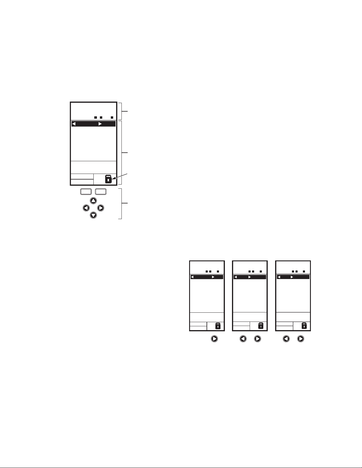
Home Screen
In the normal run state, the LCD home screen displays
the current sensed temperatures, the modulating outputs
status, the active status of the output relays, and error and
status codes.
Active relays are indicated by the small black square ()
just below the relay number. Fig. 23 shows the home
screen with relays 1, 2, and 4 energized.
Pressing the W and X buttons from the home screen
cycles through each modulating output that is paired with
the sensor it controls and the active output relays.
HOME
RELAYS 1 2 3 4
ON
SENSORS
SENSOR A
78
SENSOR B
84
MOD1 40%
MOD2 60%
DI ON
o
F
o
F
HOME
RELAYS 1 2 3 4
ON
MOD 1 40%
COOL
SETPOINT
74
SENSOR A
62
MOD1 40%
MOD2 60%
DI ON
o
F
o
F
HOME
RELAYS 1 2 3 4
ON
REL 1 ON
HEAT
SETPOINT
60
SENSOR A
62
RT 12345 HRS
MOD1 40%
MOD2 60%
DI ON
o
F
o
F
6-Button Keypad – The keypad is used to access the
menus and enter values (see “Using the LCD Panel
Interface”).
Using the LCD Panel Interface
The 6-button keypad is used to move through the menus
and enter or change parameter values.
Home Button
Pressing the HOME button at any time exits the current
Programming or Setup display screen and returns to the
home screen as shown in Fig. 22 and Fig. 23.
M24489
Fig. 23. LCD Display - Home Screen Displaying
Sensors, Active Relays, and Mod Outputs.
NOTE: The modulating output home screen and the
relay home screen do not dynamically update
the active relay status, sensor values, and
modulating output percentages. The information
is a snapshot taken when you press the W or X
button to display the screen.
IMPORTANT
After four minutes of inactivity (no buttons
pressed), the LCD display reverts to the home
screen display.
11 62-0254–03
Page 20
T775A/B/M SERIES 2000 CONTROLLER INTERFACE OVERVIEW
Accessing the Menus
Menus are used for programming, scheduling, viewing the
summary settings, and setup of advanced options.
Programming, Scheduling, and Summary Menus
To access these menus from the home screen, press the
MENU button. See Fig. 24.
MENU DISPLAY WHEN
SCHEDULING IS SET
HOME
RELAYS 1 2 3 4
ON
SENSORS
SENSOR A
78
SENSOR B
84
MOD1 40%
MOD2 60%
DI ON
menu
home
o
F
o
F
MENU
PROGRAM
SCHEDULE
SUMMARY
EXIT
OR
Fig. 24. Menus.
Depending on whether scheduling is enabled or not, the
LCD displays one of two menus as shown in Fig. 24.
Scheduling is enabled from the Setup menu’s Output
settings (see “2.3.3.1. USE SCHED” on page 24).
Setup Menu
To access the Setup menu, press and hold the MENU
button for five seconds. See Fig. 25.
MENU DISPLAY WHEN
SCHEDULING IS NOT SET
MENU
PROGRAM
EXIT
M24490
HOME
RELAYS 1 2 3 4
ON
SENSORS
SENSOR A
78
SENSOR B
84
MOD1 40%
MOD2 60%
DI ON
menu
home
o
F
o
F
FIVE
SECONDS
SETUP
SENSORS
OUTPUTS
EXIT
M24491
Fig. 25. Setup Menu.
Using the Menus
When you are working with the menus, use the:
• Left arrow button (W) to scroll backward through the
menus
• Right arrow button (X) to select the highlighted menu
item and display its content
• Up and Down arrow buttons (S and T) to scroll up
and down through a list of items or to increase or
decrease the value of a displayed parameter
NOTE: If you press the HOME button or there is no key-
pad activity for four minutes, you exit Program
mode and return to the home screen.
If you press the MENU button, you exit and
return to the menu.
62-0254–03 12
Page 21

1. PROGRAMMING T775A/B/M SERIES 2000 CONTROLLER
1. PROGRAMMING
The controller must be programmed before being placed
into service.
IMPORTANT
During programming, the controller is live at all
times. For example, the contacts may open and
close when adjusting the setpoint.
The Programming process uses a hierarchical menu
structure that is easy to use. You press the W and X
arrow buttons to move forward and backward through the
menus.
NOTES:
1. The controller interface is intuitive. You may
find that you do not need the following procedure instructions to program the controller.
You may want to use this procedure simply as
a reference to locate the particular option or
parameter of interest.
2. The menus can display only those relays that
are defined in Setup (see “2.3.2. NBR OF
RELAYS” on page 24). For example, if you
configure only two relays, then only two
relays display on the appropriate menus.
3. If you press the HOME button or there is no
keypad activity for four minutes, you exit Program mode and return to the home screen.
4. If you press the MENU button, you exit Pro-
gram mode and return to the menu.
Setpoint High Limit
You can set a single irreversible setpoint high limit
maximum value, which is applied to all outputs.
Adjust the setpoint (at any output) to the desired
maximum setpoint. Then, simultaneously press the
home, W, and X buttons and continue to press all three
buttons for five seconds to set the setpoint high limit
maximum to this value.
NOTE: You must press all three buttons at exactly the
same time for this action to occur.
IMPORTANT
1. This action sets the maximum setpoint value of
all outputs to the setpoint high limit maximum.
2. Setting the high limit setpoint maximum is irre-
versible. If you perform the action inadvertently
and this setpoint adversely affects the control of
your system, you must replace the controller.
Setpoint and Differential
The following describes the relationship between setpoint
and differential for heating and cooling. These settings are
programmed for each output relay.
Heating Mode Setpoint and Differential
In heating mode, the differential is below the setpoint. The
relay de-energizes when the temperature rises to the
setpoint. As the temperature drops to the setpoint minus
the differential, the relay energizes.
Cooling Mode Setpoint and Differential
In cooling mode, the differential is above the setpoint. The
relay de-energizes when the temperature falls to the
setpoint. As the temperature rises to the setpoint plus the
differential, the relay energizes.
13 62-0254–03
Page 22
T775A/B/M SERIES 2000 CONTROLLER 1. PROGRAMMING
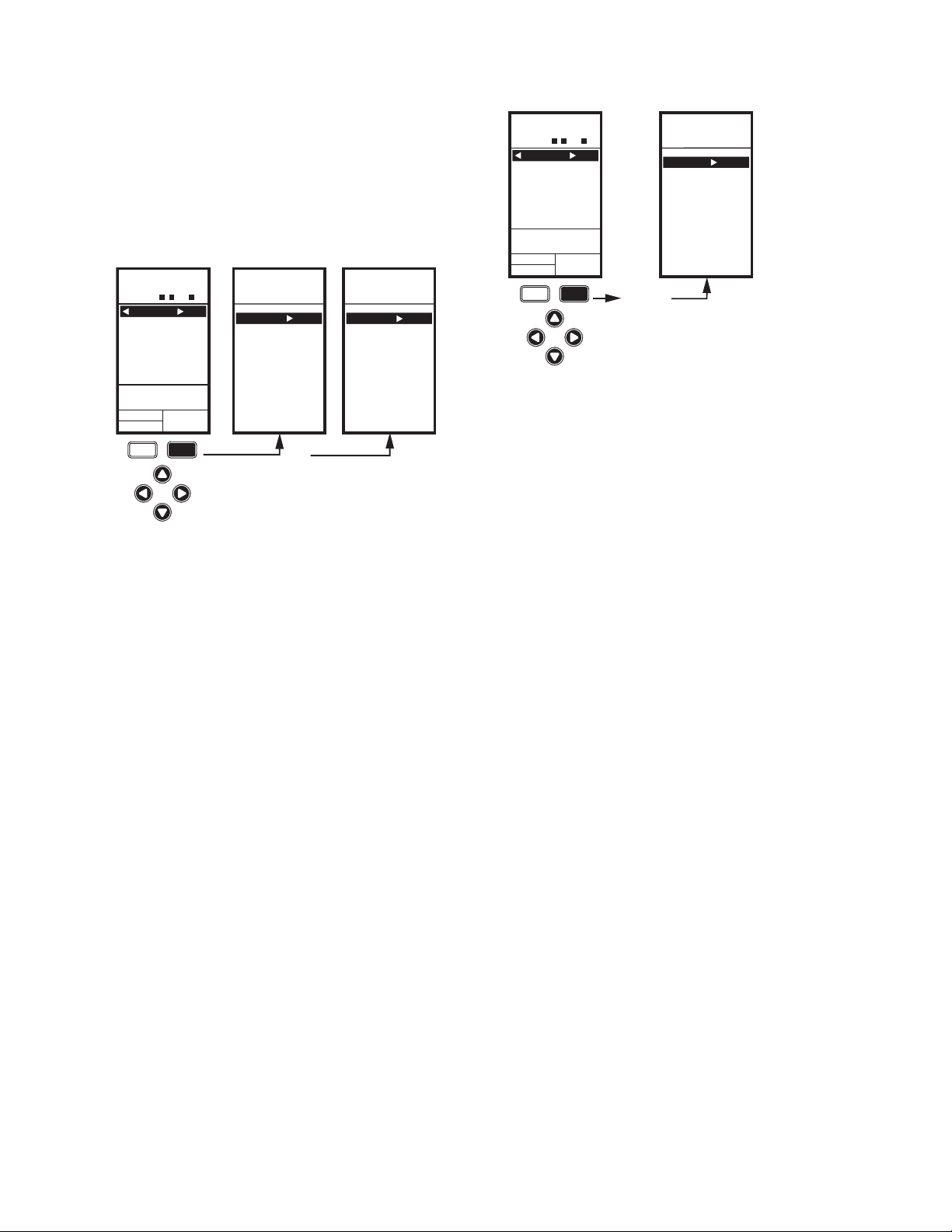
Programming the T775A/B/M Controller
To program the controller, perform the following
procedures in the order listed:
1. Enter Program mode — see “1.1. Entering Program
Mode”
2. Program the Outputs — see “1.2. Program Menu for
Outputs” on page 14
MENU
PROGRAM
MENU
PROGRAM
MOD 1
MOD 2
RELAY 1
RELAY 2
RELAY 3
RELAY 4
EXIT
OR
Fig. 26. Program Menu.
PROGRAM
RELAY 1
SETPOINT
DIFFRNTL
SENSOR
HEAT/COOL
SETBACK
EXIT
PROGRAM
RELAY 1
RELAY 2
RELAY 3
RELAY 4
EXIT
MENU
PROGRAM
RELAY 1
MENU
When programming is complete, you may continue with
“3. Scheduling” on page 30 or, for advanced options,
continue with “2. Setup (Advanced Options)” on page 17.
1.1. Entering Program Mode
Press the MENU button, then select PROGRAM and
press the X button to view the Program menu.
Fig. 26 shows the Program menus for controllers with and
without Modulating Outputs.
NOTE: Modulating outputs are not available on the
T775A and T775B controller models.
M24492
1.2. Program Menu for Outputs
Press the MENU button, select PROGRAM, then select
RELAY 1 (or MOD 1) to view the parameters. Fig. 27
shows RELAY 1.
NOTE: For MOD 1 and 2, THROT RNG replaces
DIFFRNTL.
Fig. 27. Program Menu Outputs.
PROGRAM
RELAY 1
SETPOINT
MENU
PROGRAM
RELAY 1
SETPOINT
ENTER
SETPOINT
FOR
RELAY 1
Fig. 28. Program - Setpoint.
70
NOTE: The Setback parameter displays only if schedul-
ing is enabled (see Fig. 55 on page 24) or the DI
M24493
Option is set to Setback. (see Fig. 57 on
page 25).
Continue with “1.2.1. SETPOINT”.
1.2.1. SETPOINT
1. From the menu, use the S and T buttons to high-
light SETPOINT.
2. Press the X button to display the setpoint value.
3. Use the S and T buttons to increase/decrease the
o
F
M24494
desired setpoint temperature.
Default: 70°F (21°C)
Range: -40°F to 248°F (-40°C to 120°C)
4. Press the X button to accept the setpoint tempera-
ture and display the next option.
62-0254–03 14
Page 23
1. PROGRAMMING T775A/B/M SERIES 2000 CONTROLLER
PROGRAM
RELAY 1
DIFFRNTL
MENU
PROGRAM
RELAY 1
DIFFRNTL
20
ENTER
DIFFERENTIAL
FOR
RELAY 1
o
F
M24495
Fig. 29. Program - Differential or Throttling Range.
1.2.2. DIFFERENTIAL or THROTTLING RANGE
Differential is used for Relay outputs and Throttling Range
is used for Modulating outputs.
1. From the menu, use the S and T buttons to high-
light THROT RNG or DIFFERNTL.
2. Press the X button to display the throttling range
value.
3. Use the S and T buttons to increase/decrease the
desired value.
Default: 20°F (-6.6°C)
Range: 1°F to 150°F (1°C to 66°C).
4. Press the X button to accept the value and display
the next option.
In heating mode, the Differential is below the setpoint.
The relay de-energizes when the temperature rises to the
setpoint. As the temperature drops to the setpoint minus
the Differential, the relay energizes.
In cooling mode, the Differential is above the setpoint.
The relay de-energizes when the temperature falls to the
setpoint. As the temperature rises to the setpoint plus the
Differential, the relay energizes.
The Throttling Range brackets the setpoint setting, e.g., if
the setpoint is 72°F and the throttling range is 10°F, then
the effective throttling temperature range is 67°F to 77°F.
This applies to both modulating outputs and floating
outputs.
PROGRAM
RELAY 1
SENSOR
SENSOR A
SENSOR B
SENSOR FOR
Fig. 30. Program - Sensor.
PROGRAM
RELAY 1
HEAT/COOL
HEAT
COOL
Fig. 31. Program - Heat/Cool.
MENU
PROGRAM
RELAY 1
SENSOR
SELECT
RELAY 1
MENU
PROGRAM
RELAY 1
HEAT/COOL
SELECT
HEAT/COOL
FOR
RELAY 1
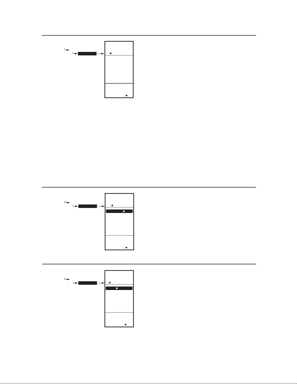
1.2.3. SENSOR
1. From the menu, use the S and T buttons to high-
light SENSOR.
2. Press the X button to display the sensor selections.
3. Use the S and T buttons to select Sensor A or B.
4. Press the X button to accept the highlighted sensor
and display the next option.
M24496
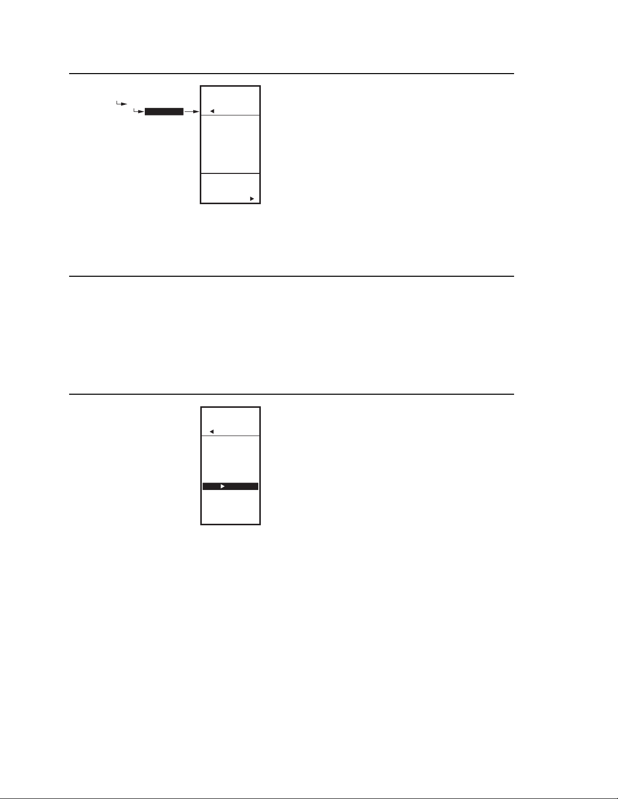
1.2.4. HEAT/COOL
1. From the menu, use the S and T buttons to high-
light HEAT/COOL.
Default: HEAT
2. Press the X button to display the heat and cool
selections.
3. Use the S and T buttons to select Heat or Cool.
4. Press the X button to accept the highlighted selec-
tion and display the next option.
M24497
15 62-0254–03
Page 24
T775A/B/M SERIES 2000 CONTROLLER 1. PROGRAMMING
PROGRAM
RELAY 1
SETBACK
Fig. 32. Program - Setback.
MENU
PROGRAM
RELAY 1
SETBACK
60
ENTER
SETBACK
SETPOINT
FOR RELAY 1
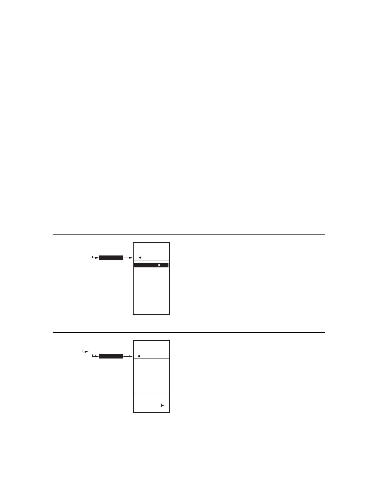
1.2.5. SETBACK
The Setback temperature option displays if scheduling is
enabled (see Fig. 55 on page 24) or the DI Option is set to
Setback. (see Fig. 57 on page 25).
This is the desired setpoint temperature that you want to
o
F
M24498
use during setback mode for this output. For example, if
your setpoint is 70°F and you want the temperature to
drop 10°F during setback mode, enter 60°F as the setpoint for this output.
1. From the menu, use the S and T buttons to high-
light SETBACK.
2. Use the S and T buttons to increase/decrease the
desired setpoint temperature.
Default: 60°F (16°C)
Range: -40°F to 248°F (-40°C to 120°C)
3. Press the X button to accept the value and display
the menu.
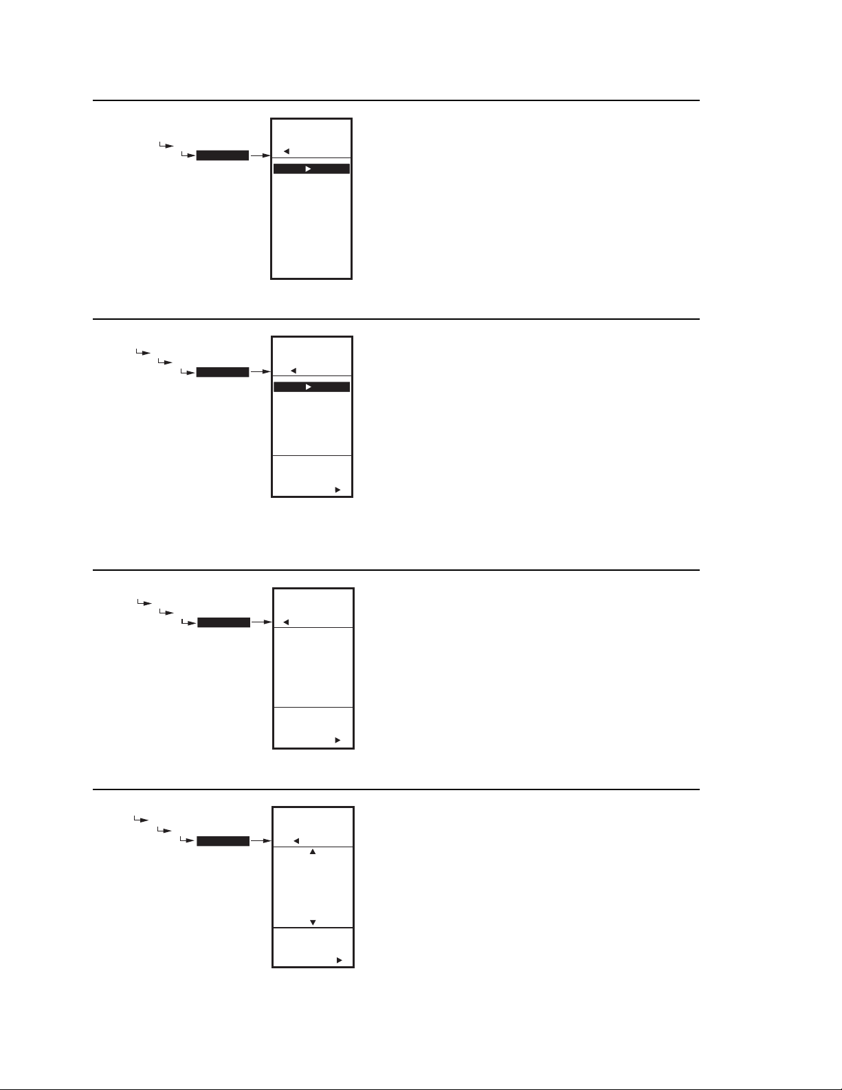
1.2.6. Program Next Output
(Mod or Relay)
For the next output (Mod or Relay), select the desired
output from the Program menu (see Fig. 26 on page 14).
Go to “1.2.1. SETPOINT” on page 14 to program the next
output.
When you finish programming the outputs, continue with
“1.2.7. Exiting Program Mode” on page 16.
MOD 1
MOD 2
RELAY 1
RELAY 2
RELAY 3
RELAY 4
EXIT
Fig. 33. Program - Exit.
MENU
PROGRAM
1.2.7. Exiting Program Mode
Press the HOME button to leave programming mode and
return to the home screen.
This completes the programming procedure.
M24499
62-0254–03 16
Page 25
2. SETUP (ADVANCED OPTIONS) T775A/B/M SERIES 2000 CONTROLLER
2. SETUP (ADVANCED OPTIONS)
Setup provides the ability to change the factory default
settings for the temperature sensors and outputs, to
enable/disable reset control, and to enable/disable
scheduling.
NOTE: The controller interface is intuitive. You may find
that you do not need the following setup
instructions for the sensors and outputs. You
may want to use this procedure simply as a
reference to locate the particular option or
parameter of interest.
NOTES:
1. If you press the HOME button or there is no
keypad activity for four minutes, you exit
Setup mode and return to the home screen.
2. If you press the MENU button, you exit Setup
mode and return to the menu.
Setup Procedure
The Setup process uses a hierarchical menu structure
that is easy to use. You press the W and X arrow buttons
to move forward and backward through the menus.
NOTE: The menus can display only those relays that
are defined in Setup (see “2.3.2. NBR OF
RELAYS” on page 24). For example, if you configure only two relays, then only two relays display on the appropriate menus.
Once in Setup mode, you use the —
• Left arrow button(W) to scroll backward through the
Setup menus
• Right arrow button (X) to select the highlighted menu
item and display its content
• Up and Down arrow buttons (S and T) to scroll up
and down through a list of items or to increase or
decrease the value of a displayed setup parameter
To change the controller ’s sensors and output setup
parameters, perform the following procedures in the order
listed:
1. Enter Setup mode — see “2.1. Entering Setup
Mode”
2. Setup Sensors — see “2.2. Setting up the Sensors”
3. Setup Outputs — see “2.3. Setting up the Outputs”
on page 21
4. Exit Setup Mode — see “2.4. EXIT Setup Mode” on
page 29
2.1. Entering Setup Mode
To enter Setup mode, press and hold the MENU button
for five seconds to display the Setup menu. See Fig. 25
on page 12.
SETUP
SENSORS
SETUP
SENSORS
# SENSORS
SENSOR A
SENSOR B
EXIT
Fig. 34. Setup - Sensors Menu.
SETUP
SENSORS
# SENSORS
SETUP
SENSORS
# SENSORS
2
ENTER
NUMBER OF
SENSORS
Fig. 35. Setup - Sensors - Number of Sensors.
M24500
M24501
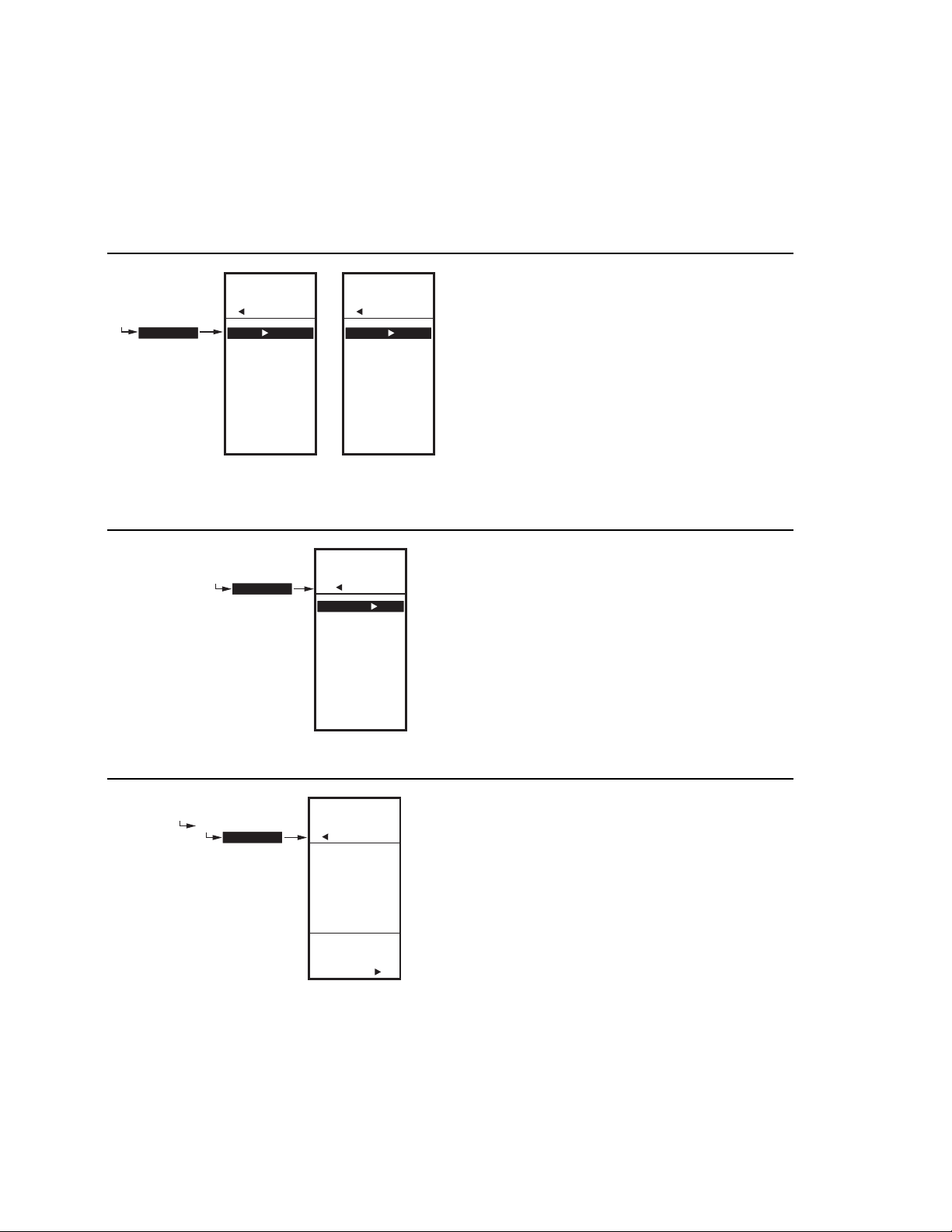
2.2. Setting up the Sensors
1. From the Setup menu, use the S and T buttons to
highlight SENSORS.
2. Press the X button to display the Sensors menu.
2.2.1. Number of SENSORS
The value entered here determines the number of
sensors displayed on the home screen.
1. From the Sensors menu, highlight # SENSORS
then press the X button to display the number of
sensors.
2. Use the S and T buttons to enter the number of
sensors (1 or 2).
Default: 2
3. Press the X button to accept the value and display
the SENSOR A selection.
17 62-0254–03
Page 26
T775A/B/M SERIES 2000 CONTROLLER 2. SETUP (ADVANCED OPTIONS)
SETUP
SENSORS
SENSOR A
SETUP
SENSORS
SENSOR A
UNITS
CALIBRATE
LABEL
EXIT
Fig. 36. Setup - Sensors - Sensor A Menu.
SETUP
SENSORS
SENSOR A
UNITS
SENSORS
SENSOR A
DEG F
DEG C
SELECT
UNITS FOR
SENSOR A
SETUP
UNITS
Fig. 37. Setup - Sensors - Sensor A - Units.
M24502
M24503
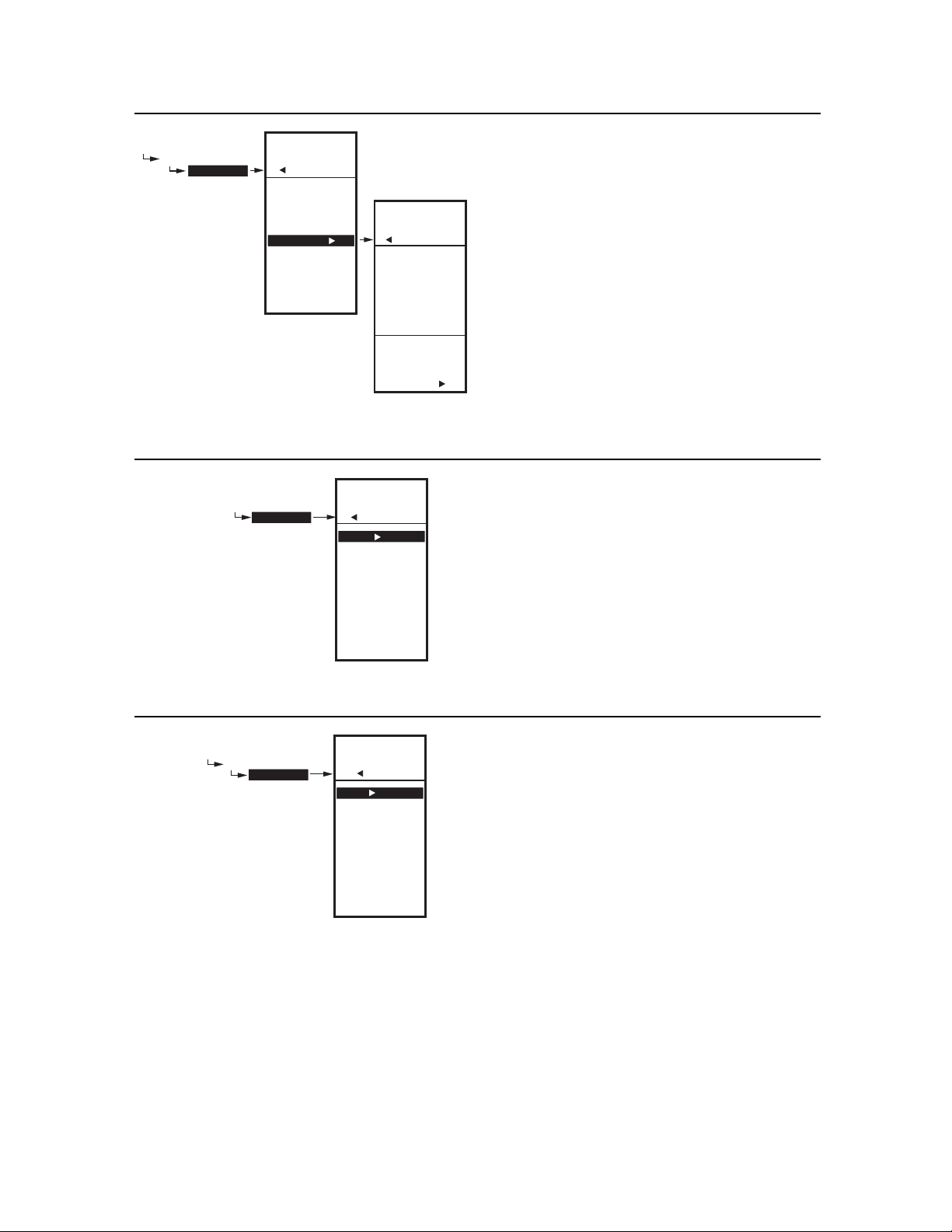
2.2.2. SENSOR A
1. From the Sensors menu, highlight SENSOR A.
2. Press the X button to display the Sensor A selec-
tions.
2.2.2.1. UNITS
IMPORTANT
1. From the Sensor A selections, use the S and T
buttons to highlight UNITS.
2. Press the X button to display the temperature units.
3. Use the S and T buttons to highlight F or C.
4. Press the X button to accept the units and return to
the Sensor A selections.
(°F or °C)
This is a global change and affects the unit
values for all temperature parameters on all
displays.
The UNITS screen displays only for Sensor A.
Default: F (Fahrenheit)
SETUP
SENSORS
SENSOR A
CALIBRATE
SETUP
SENSORS
SENSOR A
CALIBRATE
0.0
ENTER
VALUE TO
CALIBRATE
SENSOR A
o
F
Fig. 38. Setup - Sensors - Sensor A - Calibrate.
SETUP
SENSORS
SENSOR A
LABEL
SETUP
SENSORS
SENSOR A
LABEL
SENSOR A
BOILER A
OUTDOOR A
DUCT A
DISCHRG A
CHILLER A
ROOM A
SELECT
LABEL FOR
SENSOR A
Fig. 39. Setup - Sensors - Sensor A - Label.
M24504
M24505
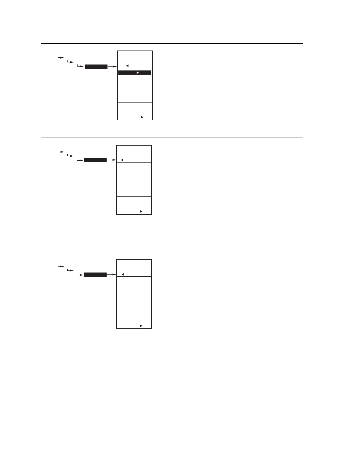
2.2.2.2. CALIBRATE
(the sensor)
Ensure that the wire size calibration value is within the
limits. See “Temperature Sensor Calibration” on page 10.
1. From the Sensor A selections, use the S and T
buttons to highlight CALIBRATE.
2. Press the X button to display the calibration degree
value.
3. Use the S and T buttons to increase/decrease the
desired calibration degrees.
Default: 0.0
Range: +/-10°F (+/-6°C)
4. Press the X button to accept the value and return to
the Sensor A selections.
2.2.2.3. LABEL
(the sensor input)
For a sensor already labeled, the display positions to and
highlights that label.
1. From the Sensor A selections, use the S and T
buttons to highlight LABEL.
2. Press the X button to display the label list.
3. Use the S and T buttons to scroll through list and
highlight the desired label.
You may need to scroll up or down to view all possible labels.
4. Use the X button to accept the highlighted label
and exit the list.
NOTE: The label names in list order are: Sensor, Boiler,
Outdoor, Duct, Dischrg, Chiller, Room, Supply,
Return, and Animals.
62-0254–03 18
Page 27

2. SETUP (ADVANCED OPTIONS) T775A/B/M SERIES 2000 CONTROLLER
SETUP
SENSORS
SENSOR A
UNITS
CALIBRATE
LABEL
EXIT
Fig. 40. Setup - Sensors - Sensor A - Exit.
SETUP
SENSORS
SETUP
SENSORS
# SENSORS
SENSOR A
SENSOR B
EXIT
SETUP
SENSORS
SENSOR B
CALIBRATE
LABEL
LIMIT
EXIT
2.2.2.4. Exit Sensor A Setup
Press the W button to exit Sensor A selections and return
to the Sensors menu.
or
Use the S and T buttons to highlight EXIT and press the
X button.
M24506
2.2.3. SENSOR B
For the T775M2030 and T775M2048 models only, which
have a High/Low modulating temperature limit, the LIMIT
item displays on the Sensor B menu.
1. From the Sensors menu, use the T button to high-
light SENSOR B.
2. Press the X button to display the Sensor B menu.
Fig. 41. Setup - Sensors - Sensor B Menu.
M24507
2.2.3.1. CALIBRATE
Setting the calibration value is accomplished the same
way as the Sensor A. See “2.2.2.2. CALIBRATE (the
sensor)” on page 18 above.
2.2.3.2. LABEL
Setting the label is accomplished the same way as the
Sensor A. See “2.2.2.3. LABEL (the sensor input)” on
page 18 above.
19 62-0254–03
Page 28

T775A/B/M SERIES 2000 CONTROLLER 2. SETUP (ADVANCED OPTIONS)
SETUP
SENSORS
SENSOR B
LIMIT
SETUP
SENSORS
SENSOR B
LIMIT
DISABLE
HI LIMIT
LOW LIMIT
SELECT
HI/LOW
LIMIT FOR
SENSOR B
Fig. 42. Setup - Sensors - Sensor B - Limit.
M24508
2.2.4. LIMIT
(Sensor B only)
For the T775M2030 and T775M2048 models only, the
LIMIT item displays on the Sensor B menu.
NOTE: The LIMIT option acts only on Modulating
Output 1.
1. From the Sensors menu, use the T button to high-
light SENSOR B.
2. Press the X button to display the Sensor B menu.
3. Use the S and T buttons to select the LIMIT item.
4. Use the X button to display the Limit selections.
5. Use the S and T buttons to select the desired limit,
(Disable, Hi Limit, or Low Limit).
Default: Disable
6. Press the X button to accept the value and return to
the Sensor B menu.
When you select Hi Limit or Low Limit, the Sensor B menu
changes and adds the Hi/Low Limit and Throttling Range
items.
If you are setting a Hi or Low Limit, continue with “2.2.4.1.
HI LIMIT or LOW LIMIT (Sensor B only)”.
If you selected Disable for the Limit value, continue with
“2.3. Setting up the Outputs” on page 21.
SETUP
SENSORS
SENSOR B
SETUP
SENSORS
SENSOR B
UNITS
CALIBRATE
LABEL
LIMIT
HI LIMIT
THROT RNG
EXIT
SETUP
SENSORS
SENSOR B
HI LIM
90
ENTER
VALUE FOR
SENSOR B
HI LIMIT
Fig. 43. Setup - Sensors - Sensor B - Hi/Low Limit
(showing Hi Limit).
o
M24509
2.2.4.1. HI LIMIT or LOW LIMIT
(Sensor B only)
Fig. 43 shows the Hi Limit (Heat mode), but the process is
the same for setting the Low Limit (Cool mode). For
proper operation, the high limit should be used only in the
Heat mode, and the low limit only in the Cool mode.
Sensor B can be assigned a high/low limit, so that as you
are controlling temperature at Sensor A, the control
adjusts its modulating output to prevent exceeding the
user-entered limit for Sensor B.
F
1. From the Sensor B menu, use the T button to high-
light HI LIMIT or LOW LIMIT.
2. Press the X button display the LIMIT value.
3. Use the S and T buttons to increase/decrease the
desired Limit value.
4. Press the X button to accept the value and return to
the Limit menu.
62-0254–03 20
Page 29
2. SETUP (ADVANCED OPTIONS) T775A/B/M SERIES 2000 CONTROLLER
SETUP
SENSORS
SENSOR B
SETUP
SENSORS
SENSOR B
UNITS
CALIBRATE
LABEL
LIMIT
HI LIMIT
THROT RNG
EXIT
SENSORS
SENSOR B
THROT RNG
VALUE FOR
SENSOR B
THROTLING
Fig. 44. Setup - Sensors - Sensor B - Throttling
Range.
SETUP
OUTPUTS
SETUP
OUTPUTS
MOD 1
MOD 2
# RELAYS
OPTIONS
RELAY 1
RELAY 2
RELAY 3
RELAY 4
EXIT
Fig. 45. Setup - Outputs Menu.
SETUP
10
ENTER
RANGE
M24510
M24511
2.2.4.2. THROTTLING RANGE
(Sensor B only)
The throttling range for the modulating high or low limit
positions the setpoint at the end of the throttling range.
For example, with a high (Heat) limit at Sensor B of 200°F
and a throttling range of 10°F, the modulating output
controlling Sensor A begins to throttle back at 190°F, and
fully closes at 200°F. Conversely, the throttling range for
the low limit begins above the Cooling setpoint in the
same manner.
o
1. From the Limit menu, use the T button to highlight
F
THROT RNG.
2. Use the S and T buttons to increase/decrease the
desired value for the Throttling Range.
Default = 0
3. Press the X button to accept the value and return to
the Limit menu.
4. Press the W button to exit the Limit menu.
5. Press the W button to exit the Sensors menu and
return to the Setup menu.
2.3. Setting up the Outputs
1. From the Setup menu, use the Sand T buttons to
highlight OUTPUTS.
2. Press the X button to display the Outputs menu.
NOTE: The menus (e.g. the Outputs menu shown here)
The following procedures set up each modulating output
and relay output.
can display only those relays that are defined in
Setup (see page 24). For example, if you configure only two relays, then only two relays display
on the appropriate menus.
SETUP
OUTPUTS
MOD 1
SETUP
OUTPUTS
MOD 1
TYPE
MIN OUT %
INTEGRAL
DERIVATIV
SCHEDULE
RESET
EXIT
2.3.1. Setting up the Modulating Outputs
1. From the Output menu, use the S and T buttons to
highlight the desired modulating output (MOD 1 or
MOD 2).
2. Press the X button to display the selected MOD
menu.
NOTE: Modulating outputs are not available on the
T775A and T775B controller models. If you are
setting up one of these controllers, skip to “2.3.2.
M24512
Fig. 46. Setup - Outputs - Modulating Output Menu.
Use the remaining procedures, beginning with “2.3.1.1.
NBR OF RELAYS” on page 24.
TYPE (of output signal)”, to set up each modulating
output. If you have two modulating outputs, repeat these
procedures for each modulating output.
21 62-0254–03
Page 30
T775A/B/M SERIES 2000 CONTROLLER 2. SETUP (ADVANCED OPTIONS)
SETUP
OUTPUTS
MOD 1
TYPE
SETUP
OUTPUTS
MOD 1
TYPE
4 - 20 mA
0-10 V
2-10 V
SERIES 90
SELECT
TYPE FOR
MOD 1
M24513
Fig. 47. Setup - Outputs - Mod Out - Type.
SETUP
OUTPUTS
MOD 1
MIN OUT %
SETUP
OUTPUTS
MOD 1
MIN OUT %
0
ENTER
MINIMUM
PERCENT FOR
MOD 1
%
M24514
Fig. 48. Setup - Outputs - Mod Out - Minimum Output
Percentage.
2.3.1.1. TYPE
(of output signal)
1. From the Mod menu, use the S and T buttons to
highlight TYPE.
2. Press the X button to display the Type selections.
3. Use the Sand T buttons to highlight the desired
output type.
Default: 4-20 mA
4. Press the X button to accept the selected type and
return to the Mod menu.
2.3.1.2. MIN OUT %
The minimum output % prevents the output from dropping
below the value entered. This value can be useful to
maintain minimum damper position.
Using the time clock or digital input to disable the output
forces the output to 0%.
1. From the Mod menu, use the S and T buttons to
highlight MIN OUT %.
2. Press the X button to display the Min Out %.
3. Use the S and T buttons to increase/decrease the
desired value from 0% to 100% in 1% increments.
Default: 0%
Range: 0 to 100%
4. Press the X button to accept the percentage and
return to the Mod menu.
SETUP
OUTPUTS
MOD 1
INTEGRAL
SETUP
OUTPUTS
MOD 1
INTEGRAL
400
ENTER
INTEGRAL
TIME FOR
MOD 1
SEC
M24515
Fig. 49. Setup - Outputs - Mod Out - Integral.
NOTES:
1. The Integral time is factory set for 400 seconds. This
is a good middle range and should satisfy many
applications. The integral time can be increased for
applications where sensed response is slow, and can
be decreased for applications where sensed
response is fast (e.g. discharge air control).
2. As a starting point, an optimal integral time for
discharge air typically ranges from 12 to 200
seconds. An optimal integral time for room control
typically ranges from 60 to 2,500 seconds. The
purpose of integral action is to reduce or eliminate
the offset from setpoint during steady state control
that is often seen in proportional only control.
2.3.1.3. INTEGRAL
1. From the Mod menu, use the S and T buttons to
highlight INTEGRAL.
2. Press the X button to display the Integral seconds.
3. Use the S and T buttons to increase/decrease the
value from 0 to 3,600 in 10 second increments.
Default: 400 seconds
Range: 0 to 3,600 seconds
4. Press the X button to accept the seconds and
return to the Mod menu.
3. Keep in mind that control is most sensitive to
throttling range. Adjust the throttling range first
before any adjustment to integral time. Adjust
throttling range to be as wide as possible to start
since this will provide the most stable control.
Remember that the integral will eliminate the steady
state error so you do not need to have a small
throttling range to have accurate control. (Integral
action allows for controlling to a setpoint even with a
wide throttling range).
62-0254–03 22
Page 31

2. SETUP (ADVANCED OPTIONS) T775A/B/M SERIES 2000 CONTROLLER
SETUP
OUTPUTS
MOD 1
DERIVATIV
SETUP
OUTPUTS
MOD 1
DERIVATIV
0
ENTER
DERIVATIVE
TIME FOR
MOD 1
SEC
M24516
Fig. 50. Setup - Outputs - Mod Out - Derivative.
SETUP
OUTPUTS
MOD 1
SCHEDULE
OUTPUTS
SCHEDULE
YES
NO
SCHEDULE
OUTPUTS
SETUP
MOD 1
USE
FOR
M24517
Fig. 51. Setup - Outputs - Mod Out - Schedule.
2.3.1.4. DERIVATIVE
The Derivative default value is factory set to zero (no
derivative control). It is strongly recommended that the
derivative remain at zero (0) unless you have a very good
reason to adjust it. Derivative control is not needed in the
vast majority of HVAC applications.
1. From the Mod menu, use the S and T buttons to
highlight DERIVATIV.
2. Press the X button to display the Derivative sec-
onds.
3. Use the S and T buttons to increase/decrease the
value.
Default: 0 (zero)
Range: 0 to 3,600 seconds
4. Press the X button to accept the seconds and
return to the Mod menu.
2.3.1.5. SCHEDULE
The Schedule option displays only if the USE SCHED
parameter is set to Yes (see page 24).
1. From the Mod menu, use the S and T buttons to
highlight SCHEDULE.
2. Use the S and T buttons to highlight YES or NO.
Default: YES
3. Press the X button to accept the selection and
return to the Mod menu.
Each output can be set up to follow or ignore the built in
scheduler. To disable the scheduler for all outputs, see
“2.3.3.1. USE SCHED” on page 24.
SETUP
OUTPUTS
MOD 1
TYPE
MIN OUT %
INTEGRAL
DERIVATIV
SCHEDULE
EXIT
Fig. 52. Setup - Outputs - Mod Out - Exit.
2.3.1.6. EXIT
Press the W button (or highlight EXIT and press the X
button) to exit the Mod menu and return to the Outputs
menu.
If you have a second modulating output to configure, go to
“2.3.1. Setting up the Modulating Outputs” on page 21.
If you are finished setting up the modulating outputs,
continue with “2.3.2. NBR OF RELAYS”.
M24518
23 62-0254–03
Page 32
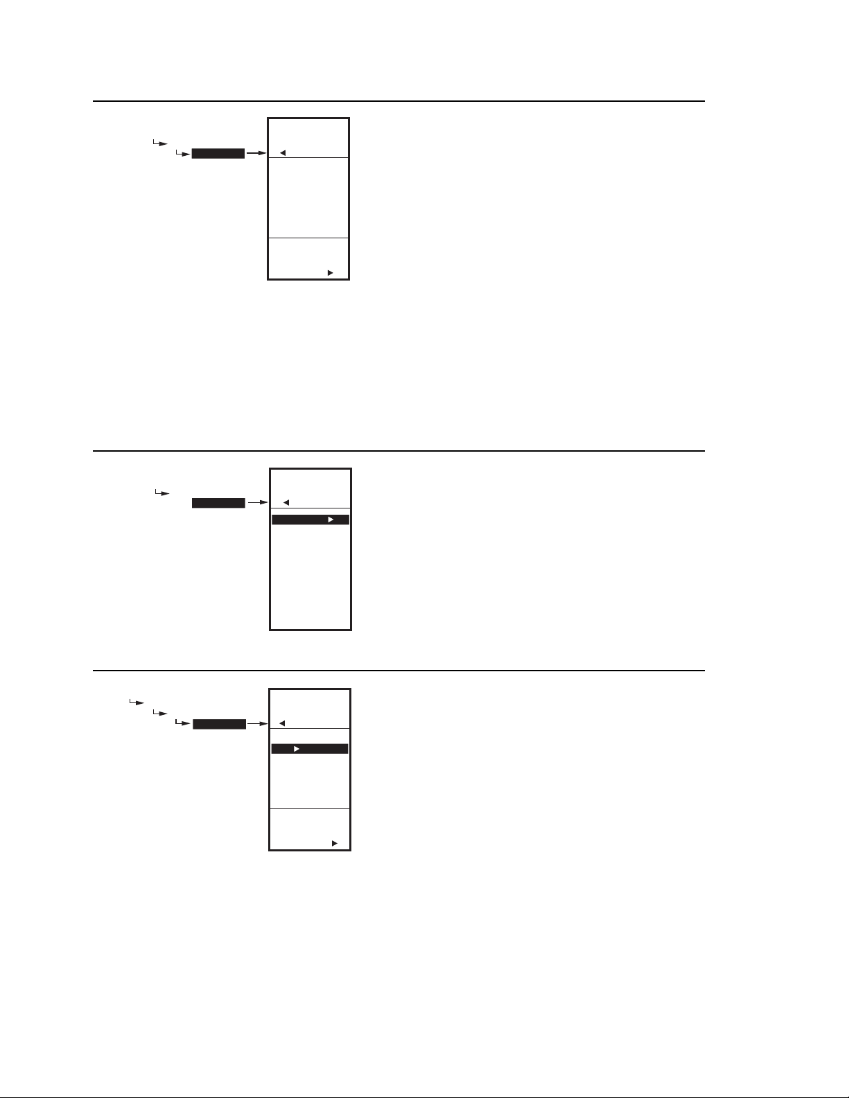
T775A/B/M SERIES 2000 CONTROLLER 2. SETUP (ADVANCED OPTIONS)
SETUP
OUTPUTS
# RELAYS
SETUP
OUTPUTS
# RELAYS
4
ENTER
NUMBER OF
RELAYS
Fig. 53. Setup - Outputs - Number of Relays.
SETUP
OUTPUTS
OPTIONS
SETUP
OUTPUTS
OPTIONS
USE SCHED
MIN OFF
DI OPTS
SHOW RT
EXIT
M24519
2.3.2. NBR OF RELAYS
1. From the Outputs menu, use the Sand T buttons
to highlight # RELAYS.
2. Press the X button to display the number of relays.
3. Use the S and T buttons to display the number
from 1 to 4 depending on the model. (See notes
below.)
4. Press the X button to accept the value and display
the Outputs menu.
NOTES:
1. The T775A/B/M models have the following
outputs available:
T775A2019 1 relay output
T775B2016 up to 2 relay outputs
T775B2024 up to 4 relay outputs
T775B2032 up to 2 relay outputs
T775B2040 up to 4 relay outputs
T775M2006 no relay outputs
T775M2014 up to 4 relay outputs
2. The number of relay outputs entered here
determines how many relays display on the
home screen.
2.3.3. OPTIONS
1. From the Outputs menu, use the Sand T buttons
to highlight OPTIONS.
2. Press the X button to display the Options menu.
M24520
Fig. 54. Setup - Outputs - Options Menu.
SETUP
OUTPUTS
OPTIONS
USE SCHED
SETUP
OUTPUTS
OPTIONS
USE SCHED
YES
NO
2.3.3.1. USE SCHED
1. Press the X button to display the schedule selec-
tions.
2. Use the Sand T buttons to highlight YES or NO.
Default: NO
3. Press the X button to accept the value and display
the MIN OFF option.
USE
SCHEDULE
FOR
OUTPUTS
Fig. 55. Setup - Outputs - Options - Schedule.
M24521
Selecting NO disables scheduling for all outputs.
Selecting YES enables scheduling for all outputs. When
YES is selected, all individual outputs default to follow the
schedule. However, each individual output can be
removed from scheduling as desired.
With Scheduling enabled, when you return to Program
mode, the new option for Scheduling displays. You can
press the home key and then the menu key to view the
Schedule options in the menu.
See “2.3.1.5. SCHEDULE” on page 23.
62-0254–03 24
Page 33
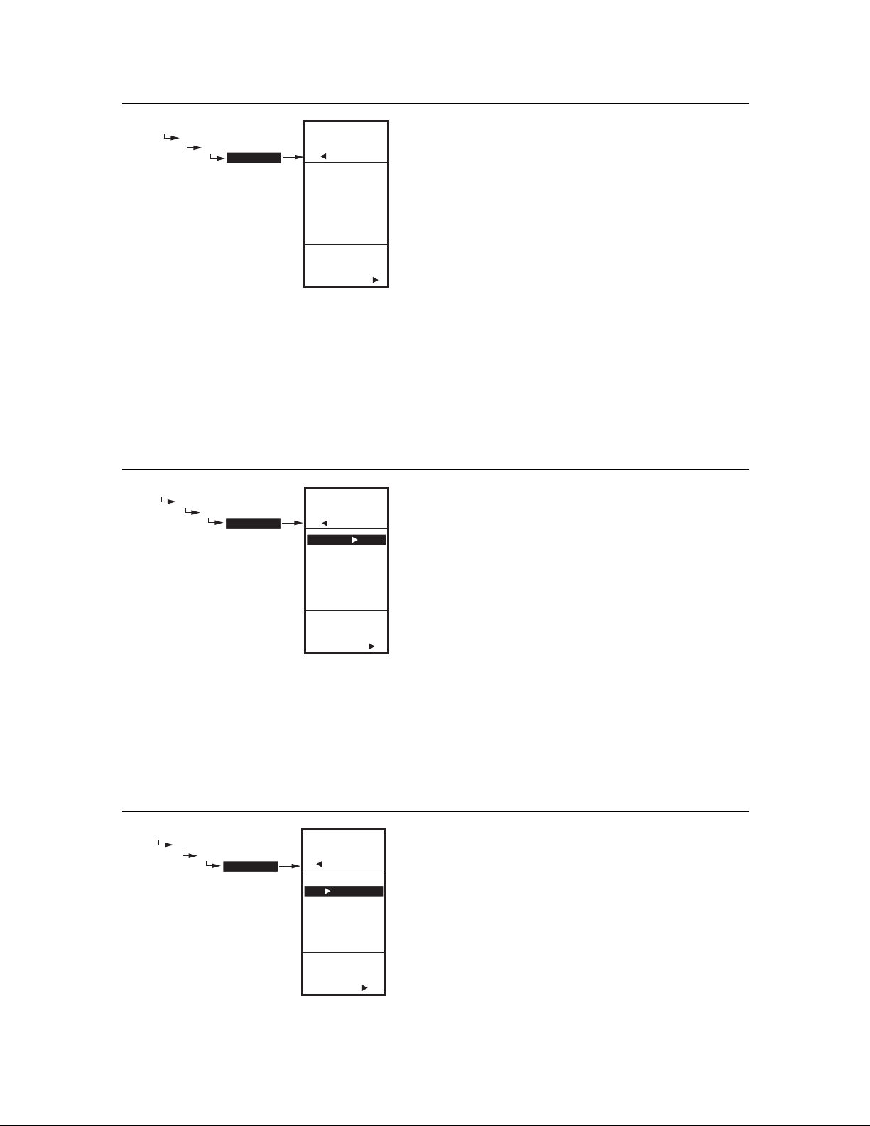
2. SETUP (ADVANCED OPTIONS) T775A/B/M SERIES 2000 CONTROLLER
SETUP
OUTPUTS
OPTIONS
MIN OFF
SETUP
OUTPUTS
OPTIONS
MIN OFF
0
ENTER
MINIMUM
OFF TIME
FOR RELAYS
SEC
M24522
Fig. 56. Setup - Outputs - Options - Min Off Time.
SETUP
OUTPUTS
OPTIONS
DI OPTS
SETUP
OUTPUTS
OPTIONS
DI OPTS
DISABLE
SETBACK
IGNORE
SELECT DI
OPTIONS
FOR
OUTPUTS
M24523
Fig. 57. Setup - Outputs - Options - DI Options.
2.3.3.2. MIN OFF
(minimum off time for all relays)
This is the minimum number of seconds of “off time” for
all relays.
1. Press the X button to display the Min Off value.
2. Use the S and T buttons to increase/decrease the
desired number of seconds from 0 to 990 seconds
in 10 second increments.
Default: 0 (zero)
Range: 0 to 990 seconds
3. Press the X button to accept the seconds and
display the DI OPTIONS.
NOTES:
1. The minimum off time applies to all relay
outputs.
2. When minimum off time is active, relays
waiting to be energized display a flashing
square underneath the relay number on the
home screen.
3. If the minimum off time is not equal to zero
(0), the minimum off time activates at powerup. To manually override, press the W button
at any time.
2.3.3.3. DI OPTIONS
(digital input options)
The DI Option you select applies to all outputs. This
option overrides any Setpoint/Setback values entered in
the Schedule.
1. Press the X button to display the DI Option selec-
tions.
2. Use the S and T buttons to highlight DISABLE,
SETBACK, or IGNORE.
Default: DISABLE
3. Press the X button to accept the value and display
the SHOW RT option.
When the digital input (DI) closes, all outputs follow the DI
option value (Disable, Setback, or Ignore):
• DISABLE disables the outputs; relays return to de-
energized state and Mod outputs return to 0% output.
• SETBACK enables a setback temperature value to be
programmed for each output.
— To program the Setback temperature, see Fig. 32
on page 16.
• IGNORE causes the digital input to have no effect on
the Relay or Mod outputs.
SETUP
OUTPUTS
OPTIONS
SHOW RT
YES
NO
SETUP
OUTPUTS
OPTIONS
SHOW RT
USE
RUNTIME
FOR
RELAYS
M24524
Fig. 58. Setup - Outputs - Options - Show Runtime.
2.3.3.4. SHOW RT
(show run time hours)
1. Press the X button to display the Show RT values.
2. Use the S and T buttons to select YES or NO.
Default: YES
3. Press the X button to accept the value and return to
the Options menu.
Selecting YES shows the RT (run time) hours for each
relay on the home screen displays.
NOTE: Run times can be reset to zero for each individ-
ual relay. You must do this for each relay that
you want to reset to zero. See “2.3.4.3. RESET
RT (run time hours)” on page 28.
25 62-0254–03
Page 34
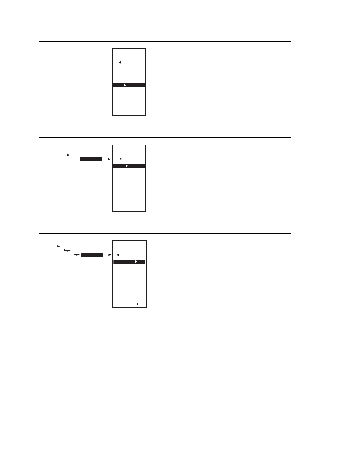
T775A/B/M SERIES 2000 CONTROLLER 2. SETUP (ADVANCED OPTIONS)
SETUP
OUTPUTS
OPTIONS
USE SCHED
MIN OFF
DI OPTION
SHOW RT
EXIT
Fig. 59. Setup - Outputs - Options - Exit.
SETUP
OUTPUTS
RELAY 1
SETUP
OUTPUTS
RELAY 1
TYPE
SCHEDULE
RESET
RESET RT
EXIT
Fig. 60. Setup - Outputs - Relay Menu.
M24525
M24526
2.3.3.5. Exit Options Setup
Press the W button (or highlight EXIT and press the X
button) to exit and return to the Outputs menu.
Continue with “2.3.4. Setting up the Relays”
2.3.4. Setting up the Relays
1. From the Outputs menu, use the S and T buttons
to highlight the desired relay (1-4 depending on
model).
2. Press the X button to display the selected relay
menu.
The TYPE selection shown in Fig. 60 displays only for
Relay 1 and Relay 3.
Continue with the remainder of section 3.4 to setup the
relay outputs.
SETUP
OUTPUTS
RELAY 1
TYPE
SETUP
OUTPUTS
RELAY 1
TYPE
STANDARD
FLOATING
2.3.4.1. TYPE
(standard or floating)
The Floating option is only available on the T775B2016,
T775B2024, T775B2032, and T775B2040 models.
For these models, this selection displays only for Relay 1
and/or Relay 3.
1. Press the X button to display the Type values.
2. Use the S and T buttons to select STANDARD OR
SELECT
TYPE FOR
RELAY 1
Fig. 61. Setup - Outputs - Relay - Type.
M24527
FLOATING.
Default: STANDARD (not floating)
3. Press the X button to accept the value and return to
the Relay menu.
If you select FLOATING, the relays are paired (1-2 or 3-4)
and are setup together. Continue with “2.3.4.1.1. Floating
Relay Menu”.
If you select STANDARD, go to “2.3.4.2. SCHEDULE” on
page 28.
62-0254–03 26
Page 35
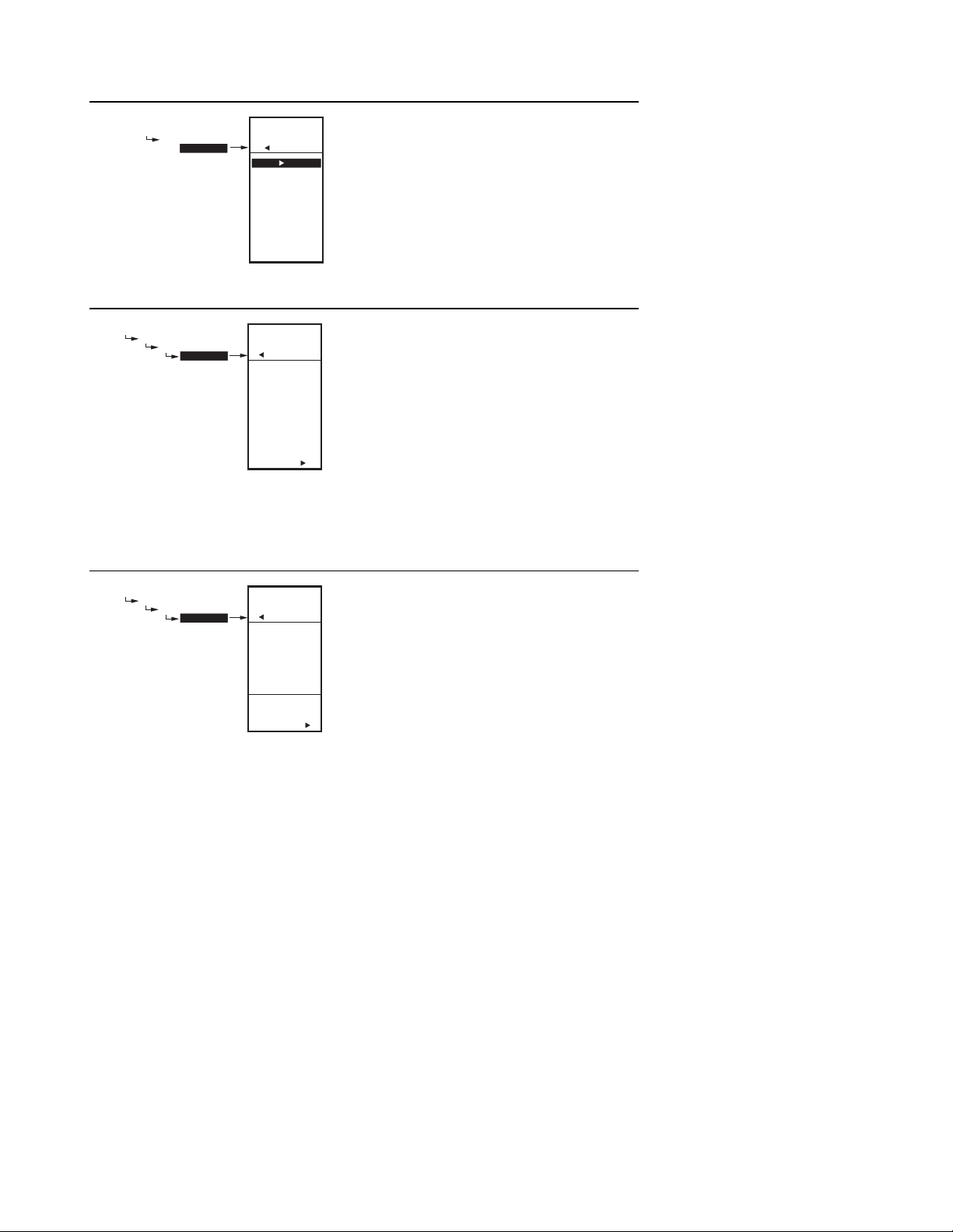
2. SETUP (ADVANCED OPTIONS) T775A/B/M SERIES 2000 CONTROLLER
SETUP
OUTPUTS
FLOAT 1
SETUP
OUTPUTS
FLOAT 1
TYPE
ACTUATOR
INTEGRAL
DERIVATIV
SCHEDULE
RESET
EXIT
M24528
Fig. 62. Setup - Outputs - Floating Relay - Menu.
SETUP
OUTPUTS
FLOAT 1
ACTUATOR
SETUP
OUTPUTS
FLOAT 1
ACTUATOR
90
ENTER
ACTUATOR
TIMING FOR
FLOAT 1
SEC
M24529
Fig. 63. Setup - Outputs - Floating Relay - Actuator.
2.3.4.1.1. Floating Relay Menu
The Floating option is only available on the T775B2016,
T775B2024, T775B2032, and T775B2040 models.
When Relay 1 or Relay 3 is setup as floating, relays are
paired and the Float 1 or Float 2 menu displays with the
selections shown in Fig. 62.
2.3.4.1.1.1. ACTUATOR
The Actuator option displays only on the T775B2016,
T775B2024, T775B2032, and T775B2040 models when
the Type option = Floating.
1. From the menu, use the S and T buttons to high-
light ACTUATOR.
2. Press the X button to display the actuator value.
3. Use the S and T buttons to increase/decrease the
desired number of seconds.
Default: 90 seconds
Range: 0 to 3,600 seconds)
4. Press the X button to accept the value and display
the INTEGRAL option.
The actuator run time is defined as the time needed to
move the actuator from the fully closed to fully open
position and visa versa.
(floating relay only)
SETUP
OUTPUTS
FLOAT 1
INTEGRAL
SETUP
OUTPUTS
FLOAT 1
INTEGRAL
400
ENTER
INTEGRAL
TIME FOR
FLOAT 1
SEC
M24530
Fig. 64. Setup - Outputs - Floating Relay - Integral.
2.3.4.1.1.2. INTEGRAL (
The Actuator option displays only on the T775B2016,
T775B2024, T775B2032, and T775B2040 models when
the Type option = Floating.
1. From the menu, use the S and T buttons to high-
light INTEGRAL.
2. Press the X button to display the actuator value.
3. Use the S and T buttons to increase/decrease the
desired number of seconds.
Default: 400 seconds
Range: 0 to 3,600 seconds)
4. Press the X button to accept the value and display
the DERIVATIV option.
See Integral NOTES on page 22 for additional information
about setting the Integral time.
modulating/floating relay only)
27 62-0254–03
Page 36
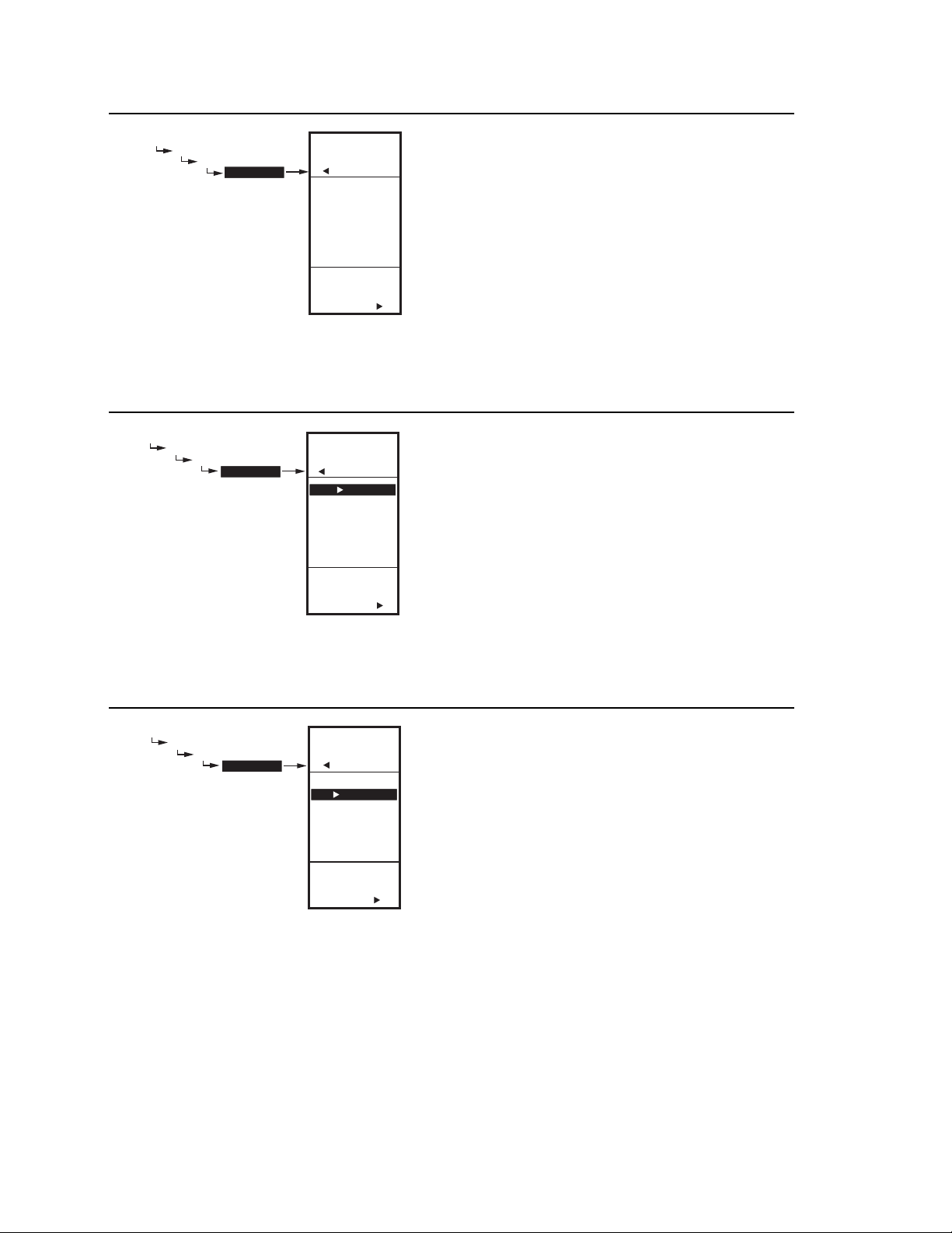
T775A/B/M SERIES 2000 CONTROLLER 2. SETUP (ADVANCED OPTIONS)
SETUP
OUTPUTS
FLOAT 1
DERIVATIV
SETUP
OUTPUTS
FLOAT 1
DERIVATIV
0
ENTER
DERIVATIVE
TIME FOR
FLOAT 1
SEC
M24531
Fig. 65. Setup - Outputs - Floating Relay - Derivative.
SETUP
OUTPUTS
RELAY 1
SCHEDULE
OUTPUTS
RELAY 1
SCHEDULE
YES
NO
SCHEDULE
OUTPUTS
SETUP
USE
FOR
M24532
Fig. 66. Setup - Outputs - Relay - Schedule.
2.3.4.1.1.3. DERIVATIVE
(modulating/floating relay only)
The Derivative option displays only on the T775B2016,
T775B2024, T775B2032, and T775B2040 models when
the Type option = Floating.
1. From the menu, use the S and T buttons to high-
light DERIVATIV.
2. Press the X button to display the actuator value.
3. Use the S and T buttons to increase/decrease the
desired number of seconds.
Default: 0 seconds
Range: 0 to 3,600 seconds)
4. Press the X button to accept the value and display
the SCHEDULE option.
Continue with “2.3.4.2. SCHEDULE” for the remaining
relay selections.
2.3.4.2. SCHEDULE
This selection displays only if “Use Sched = YES” is
selected during the Output Options setup (see page 24).
When selected, individual outputs default to follow the
schedule.
1. Press the X button to display the Schedule values.
2. Use the S and T buttons to select YES or NO.
Default: YES
3. Press the X button to accept the value and return to
the Relay menu.
An individual output can be selected to be controlled or
not controlled by the schedule.
SETUP
OUTPUTS
RELAY 1
RESET RT
YES
NO
SETUP
OUTPUTS
RELAY 1
RESET RT
RESET
RUN TIME
FOR
RELAY 1
M24533
Fig. 67. Setup - Outputs - Relay - Reset Runtime.
If NO is selected, the Setback selection does not appear
in the Program menu for this output.
2.3.4.3. RESET RT
(run time hours)
This selection displays only if “Show RT = YES” is
selected during Output Options setup (see page 25).
1. From the Relay menu, press the X button to display
the Reset RT values.
2. Use the S and T buttons to select YES or NO.
Default: NO
3. Press the X button to accept the value and return to
the Relay menu.
Selecting YES immediately resets the output run time
hours to zero for this output. When you subsequently
return to this screen, the RESET RT defaults to NO.
NOTE: Run times can be reset to zero for each individ-
ual relay. You must do this for each relay that
you want to reset to zero.
62-0254–03 28
Page 37

2. SETUP (ADVANCED OPTIONS) T775A/B/M SERIES 2000 CONTROLLER
SETUP
OUTPUTS
RELAY 1
RESET
SCHEDULE
RESET RT
EXIT
Fig. 68. Setup - Outputs - Relay - Exit.
M24534
2.4. EXIT Setup Mode
Press the W button to exit the selected relay set up and
return to the Outputs menu.
To setup the next relay output go to “2.3.4. Setting up the
Relays” on page 26.
If you are finished setting up the relay outputs, press the
HOME button to exit Setup mode and return to the home
screen display.
This completes the Setup procedure.
29 62-0254–03
Page 38
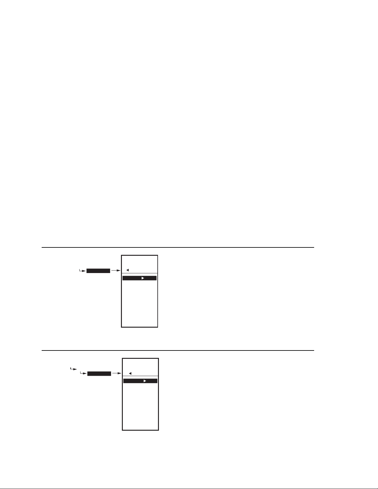
T775A/B/M SERIES 2000 CONTROLLER 3. SCHEDULING
3. SCHEDULING
Scheduling provides the ability to set daily temperature
settings for up to two events per day. Typically, these are
the daytime (setpoint) and the nighttime (setback)
settings.
IMPORTANT
To enable Scheduling, you must first enter Setup
mode (press and hold the MENU button for 5
seconds), select OUTPUTS, select OPTIONS,
select USE SCHED, and then select YES. (see
“2.3.3.1. USE SCHED” on page 24).
IMPORTANT
To properly account for Daylight Saving time, be
sure to set the Date before setting the Time.
See “3.2.2. SET DATE” on page 31.
NOTE: Each output is independently configurable to
follow the schedule or not. For modulating
outputs, see “2.3.1.5. SCHEDULE” on page 23.
For relay outputs, see “2.3.4.2. SCHEDULE” on
page 28.
NOTE: The controller interface is intuitive. You may find
that you do not need the following scheduling
instructions. You may want to use this procedure
simply as a reference to locate the particular
option or parameter of interest.
NOTES:
1. If you press the HOME button or there is no
keypad activity for four minutes, you exit
Scheduling mode and return to the home
screen.
2. If you press the MENU button, you exit
Scheduling mode and return to the menu.
To create or change a schedule, you use the —
• Left arrow button (W) to scroll backward through the
Schedule menus
• Right arrow button (X) to select the highlighted menu
item and display its content
• Up and Down arrow buttons (S and T) to scroll up
and down through a list of items or to increase or
decrease the value of a displayed schedule parameter
Creating a Schedule
To create a schedule, perform the following in the order
listed:
1. Enable Scheduling in Setup mode - see “2.3.3.1.
USE SCHED” on page 24
2. Enter Schedule mode — see “3.1. Entering Sched-
ule Mode”
3. Set the Schedule Options — see “3.2. OPTIONS”
4. Set Individual Schedules — begin with “3.3. Setting
Individual Schedules” on page 32
5. Exit Schedule Mode — see “3.4. Exiting Scheduling
Mode” on page 33
MENU
SCHEDULE
MENU
SCHEDULE
OPTIONS
MON-FRI
SAT-SUN
MONDAY
TUESDAY
WEDNESDAY
THURSDAY
FRIDAY
SATURDAY
SUNDAY
EXIT
M24536
3.1. Entering Schedule Mode
Press the MENU button, then select SCHEDULE and
press the X button to view the Schedule menu.
Fig. 69. Schedule - Menu.
MENU
SCHEDULE
OPTIONS
MENU
SCHEDULE
OPTIONS
SET TIME
SET DATE
DAYLIGHT
EXIT
3.2. OPTIONS
1. From the Schedule menu, use the S and T buttons
to highlight OPTIONS.
2. Press the X button to display the Options menu.
M24537
Fig. 70. Schedule - Options Menu.
62-0254–03 30
Page 39
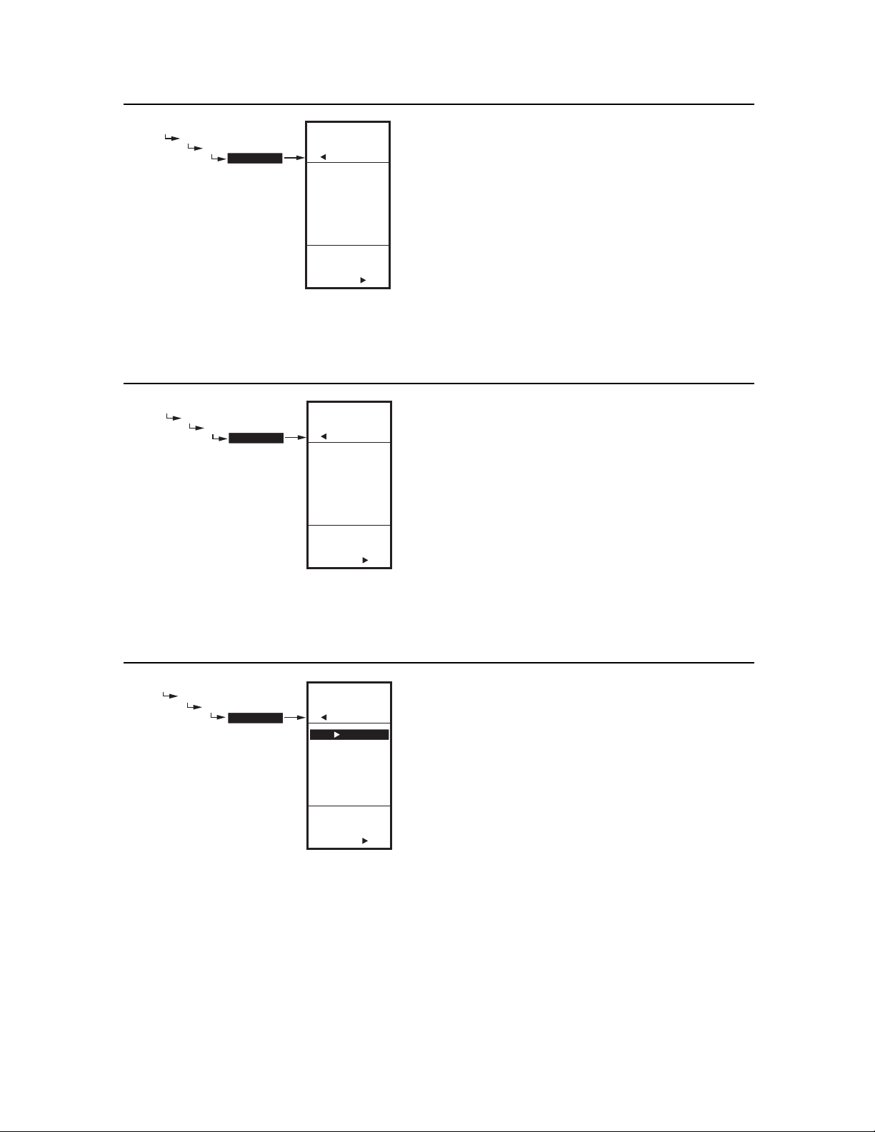
3. SCHEDULING T775A/B/M SERIES 2000 CONTROLLER
MAIN
SCHEDULE
OPTIONS
SET TIME
MAIN
SCHEDULE
OPTIONS
SET TIME
08:12 AM
SET
SYSTEM
TIME
Fig. 71. Schedule - Options - System Time.
MAIN
SCHEDULE
OPTIONS
SET DATE
MAIN
SCHEDULE
OPTIONS
SET DATE
01/01/2007
SET
SYSTEM
DATE
Fig. 72. Schedule - Options - System Date.
M24538
M24539
3.2.1. SET TIME
Setting the system time is required to enable the
controller to follow daylight saving time.
IMPORTANT
Set the Date before setting the Time. See
“3.2.2. SET DATE”.
1. From the Options menu, use the S and T buttons
to highlight SET TIME.
2. Press the X button to display the current system
time setting.
3. Use the X button to cycle between the hour,
minute, and AM/PM values.
4. Use the S and T buttons to increase/decrease the
desired value for the hour, minute, and AM/PM.
5. Press the W button to accept the Time and return to
the Options menu.
3.2.2. SET DATE
Setting the system date is required to enable the
controller to follow daylight saving time.
IMPORTANT
To properly account for Daylight Saving time, be
sure to set the Date before setting the Time.
1. From the Options menu, use the S and T buttons
to highlight SET DATE.
2. Press the X button to display the current system
date setting.
3. Use the X button to cycle between the month, day,
and year values.
4. Use the S and T buttons to increase/decrease the
desired value for the month, day, and year.
5. Press the W button to accept the Date and return to
the Options menu.
MAIN
SCHEDULE
OPTIONS
DAYLIGHT
SCHEDULE
OPTIONS
DAYLIGHT
YES
NO
DAYLIGHT
SAVING
MAIN
USE
TIME
M24540
Fig. 73. Schedule - Options - Daylight Saving Time.
3.2.3. DAYLIGHT
(daylight saving time)
1. From the Options menu, use the S and T buttons
to highlight DAYLIGHT.
2. Press the X button to display the current system
setting for daylight saving time.
3. Use the S and T buttons to select YES or NO.
Default: YES
4. Press the X button to accept the value and return to
the Options menu.
5. From the Options menu, use the Use the S and T
buttons to highlight EXIT.
6. Press the X button to return to the Schedule menu.
31 62-0254–03
Page 40
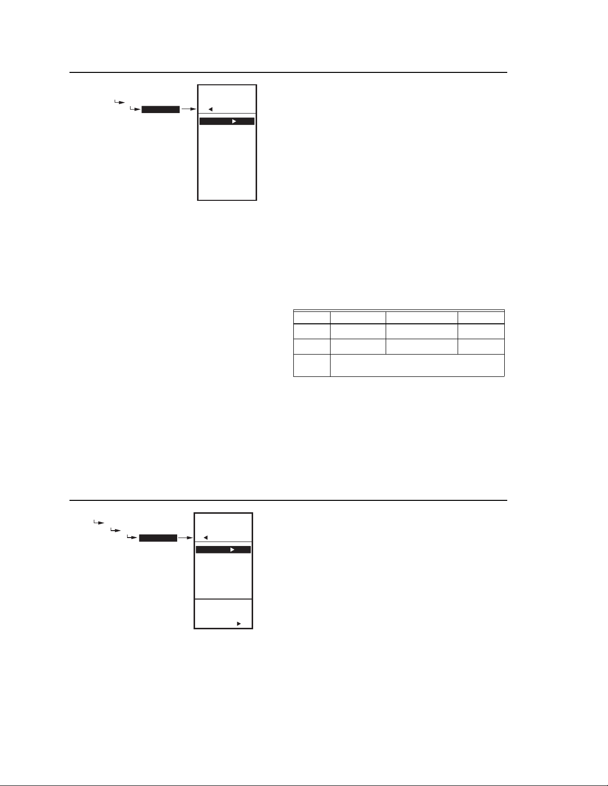
T775A/B/M SERIES 2000 CONTROLLER 3. SCHEDULING
MENU
SCHEDULE
MON-FRI
MENU
SCHEDULE
MON-FRI
E1 SETPT
E1 TIME
E2 SETPT
E2 TIME
EXIT
M24541
Fig. 74. Schedule Event Menu (Showing MON-FRI).
3.3. Setting Individual Schedules
As shown in the Schedule menu (Fig. 69 on page 30),
schedules can be set for the following time periods:
• Monday through Friday
• Saturday and Sunday
• Individual days of the week
1. From the Schedule menu, use the S and T buttons
to highlight the desired time period.
2. Press the X button to display the Schedule menu
for the selected time period.
For each selected time period, the schedule event (E1
and E2) parameters are exactly the same as shown in
Fig. 74.
SCHEDULING EXAMPLE
Setting the schedule is independent of the temperature
settings for the relay outputs. The following illustrates a
weekly schedule for daytime (setpoint) and night time
(setback) use and shows the factory default settings:
Table 4. Mon-Fri Schedule Defaults
DAY EVENT SETPT ACTION TIME
Mon-Fri Event 1 (E1) Setpoint
Mon-Fri Event 2 (E2) Setback
Sat-Sun Not used; remains in Setback from Mon-Fri
E2 settings
a
Setpoint time span is 6:00 AM until 5:59 PM because
setback starts at 6:00 PM.
b
Setback time span is 6:00PM until 5:59 AM because
setpoint starts at 6:00 AM.
6:00 AM
6:00 PM
a
b
To set a schedule, continue with “3.3.1. E1 SETPT
(setpoint for event 1)”.
The following figures show the MON-FRI menu, but the
menu selections are the same for any time period.
MAIN
SCHEDULE
MON-FRI
E1 SETPT
MENU
SCHEDULE
MON-FRI
E1 SETPT
SETPOINT
SETBACK
NOT USED
3.3.1. E1 SETPT
(setpoint for event 1)
1. From the selected time period menu, use the S and
T buttons to highlight E1 SETPT.
2. Press the X button to display the setpoint options.
3. Use the S and T buttons to highlight the desired
option.
4. Press the X button to accept the value and return to
the selected time period menu.
SELECT
SETPOINT
FOR
EVENT 1
M24542
Fig. 75. Schedule - Event 1 Setpoint.
62-0254–03 32
Page 41
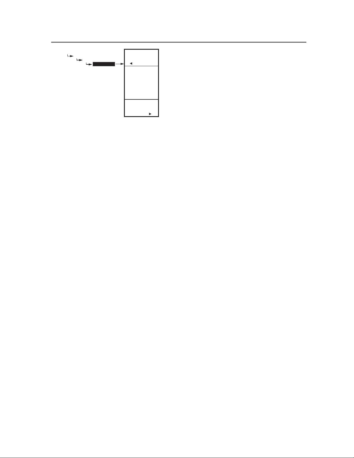
3. SCHEDULING T775A/B/M SERIES 2000 CONTROLLER
MAIN
SCHEDULE
MON-FRI
E1 TIME
Fig. 76. Schedule - Event 1 Time.
MAIN
SCHEDULE
MON-FRI
E1 TIME
6:00 AM
SET
TIME
FOR
EVENT 1
M24543
3.3.2. E1 TIME
(time for event 1)
1. From the selected time period menu, use the S and
T buttons to highlight E1 TIME.
2. Press the X button to display the current time set-
ting for event 1.
3. Use the X button to cycle between the hour,
minute, and AM/PM values.
4. Use the S and T buttons to increase/decrease the
desired value for the hour, minute, and AM/PM.
5. Press the W button to accept the time and return to
the selected time period menu.
3.3.3. E2 SETPOINT
(setpoint for event 2)
Creating the setpoint for event 2 is accomplished the
same way as the first event. See “3.3.1. E1 SETPT
(setpoint for event 1)” on page 32 above.
3.3.4. E2 TIME
(time for event 2)
Creating the time for event 2 is accomplished the same
way as the first event. See “3.3.2. E1 TIME (time for event
1)” above.
3.3.5. EXIT
(exit from selected time period settings)
After entering the time for event 2, use the W button to exit
the schedule time period and return to the Schedule menu
(Fig. 69 on page 30) to select a different time period.
When you finish scheduling the time periods, continue
with “3.4. Exiting Scheduling Mode”.
3.4. Exiting Scheduling Mode
Press the HOME button to exit the Schedule menu and
return to the home screen display.
This completes the Scheduling procedure.
33 62-0254–03
Page 42
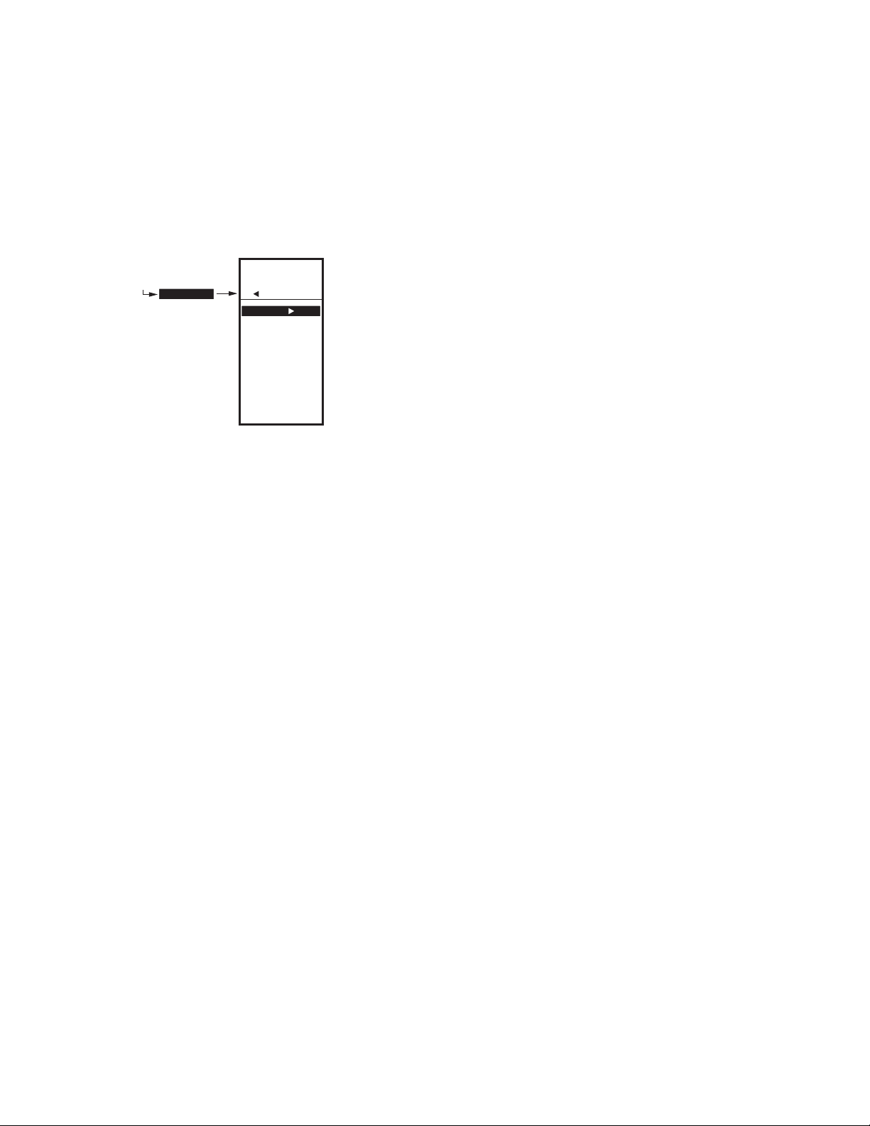
T775A/B/M SERIES 2000 CONTROLLER SUMMARY MENU
SUMMARY MENU
The Summary menu provides the ability to view the
schedule (E1 and E2 times) for each relay for each day of
the week.
NOTE: Scheduling must be enabled for the Summary
For each relay, the Summary display indicates the time
and temperature (in parenthesis) for each of the two
scheduled events E1 and E2.
When finished, press the home key to return to the home
display screen.
menu to display. Enabling the schedule is
determined in the Setup process for the Output
Options (see page 24).
MENU
SUMMARY
Fig. 77. Summary Example - Monday Settings.
1. Press the MENU button to view the menu.
2. Use the S and T buttons to highlight SUMMARY.
3. Press the X button to display the Summary
settings.
4. Use the X button to scroll forward through each day
of the week (Monday, Tuesday, Wednesday,
Thursday, Friday, Saturday, and Sunday).
5. While viewing a specific day, use the S and T
buttons to cycle through the individual relay
schedules for that day.
MENU
SUMMARY
MONDAY
RELAY 1-2
E1: 06:00AM (72)
E2: 06:00PM (65)
M24545
TROUBLESHOOTING
Power Loss
The date and time settings are retained for 24 hours after
a power outage. After a power loss of more than 24 hours,
the date and time settings may need to be reentered. All
other settings are stored permanently.
Errors and Diagnostics
The controller provides an error message and diagnostic
status as described below.
Error Message
There is a two-character error code that displays in
response to controller software problems:
EE
EEPROM Failure — The values read back from
the EEPROM are not the same as written into the
EEPROM. This error cannot be field repaired. Replace
the device.
Diagnostic Messages
There are two diagnostic messages that can display in
response to sensor problems. The diagnostic codes that
can flash on the display are:
– –
Sensor Open or Shorted — Two dashes display
when a sensor (typically temperature) is open or
shorted. An open circuit is considered anything
greater than 1570 ohms (greater than 300F), shorted
anything less than 770 ohms (less than -73F). Whichever stages are operating with this sensor cease to
control (meaning relays go to OFF and proportional
outputs go to zero percent).
This message can also mean that the sensor is programmed, but not physically connected.
-60°F or 270°F (-51°C or 132°C) Blinking
Blinking relay status
62-0254–03 34
Temperature Out of Range — The temperature
display blinks when the sensed temperature range is
outside of the display range, below -60°F (-51°C) or
above 270°F (132°C). The displayed value remains at
that displayed limit and control continues. Controller
continues to function unless an open or shorted state
is detected.
Relay Minimum Off Time is Active — On the home
screen, each relay’s indicator () blinks while the
relay’s minimum off time is active.
Page 43

SPECIFICATIONS T775A/B/M SERIES 2000 CONTROLLER
SPECIFICATIONS
Power: 24, 120, or 240 Vac; 50/60 Hz;
A separate earth ground is required for any power source.
Power Consumption:
• 8 VA maximum at 60 Hz
• 10 VA maximum at 50 Hz
Operating & Storage Temperature Ambient Rating:
• -40°F to 125°F (-40°C to 52°C) @ 50 Hz
• -40°F to 140°F (-40°C to 60°C) @ 60 Hz
Relative Humidity: 5% to 95% non-condensing
Relay Contact Output Ratings (N.O. and N.C.):
• 1/2 hp; 9.8 AFL, 58.8 ALR @ 120 Vac
• 1/2 hp; 4.9 AFL, 29.4 ALR @ 240 Vac
• 125 VA pilot duty @ 120/240 Vac
• 10A @ 24 Vac (resistive)
Modulating Outputs:
• 0-10 Vdc; drive a minimum of 2,000 Ohms
• 2-10 Vdc; drive a minimum of 2,000 Ohms
• 4-20 mA; drive a maximum of 600 Ohms
• Electronic Series 90
• Floating
DoC
Emissions Compliance
EN 55022: 2006
CISPR 22: 2006
VCCI V-3/2006.04
ICES-003, Issue 4: 2004
FCC PART 15 SUBPART B Class B Limit
Immunity Compliance
EN 61000-6-1: 2001 covering
EN 61000-4-2: 1995 + A1: 1998 + A2: 2001
EN 61000-4-3: 2002
EN 61000-4-4: 2004
EN 61000-4-5: 1995 + A1: 2001
EN 61000-4-6: 1996 + A1: 2001
EN 61000-4-8: 1993 + A1: 2001
EN 61000-4-11 2nd Ed.: 2004
Safety Compliance
UL 60730-1 and Part 2-9 for US and Canada
FCC Compliance Statement:
This equipment has been tested and found to comply with
limits for a Class B digital device, pursuant to Part 15 of
the FCC rules. These limits are designed to provide
reasonable protection against harmful interference in
residential installations. This equipment generates, uses,
and can radiate radio frequency energy, and if not
installed and used in accordance with the instructions,
may cause harmful interference to radio communications.
However, there is no guarantee that interference will not
occur in a particular installation. If this equipment does
cause interference to radio or television equipment
reception, which can be determined by turning the
equipment off and on, the user is encouraged to try to
correct the interference by one or more of the following
measures:
— Reorient or relocate the receiving antenna
— Move the equipment away from the receiver
— Plug the equipment into an outlet on a circuit different
from that to which the receiver is connected
— Consult the dealer or an experienced radio/television
technician for additional suggestions
You are cautioned that any change or modifications to the
equipment not expressly approve by the party responsible
for compliance could void Your authority to operate such
equipment.
This device complies with Part 15 of the FCC Rules.
Operation is subjected to the following two conditions 1)
this device may not cause harmful interference and 2) this
device must accept any interference received, including
interference that may cause undesired operation.
35 62-0254–03
Page 44

DOC T775A/B/M SERIES 2000 CONTROLLER
Automation and Control Solutions
Honeywell International Inc. Honeywell Limited-Honeywell Limitée
1985 Douglas Drive North 35 Dynamic Drive
Golden Valley, MN 55422 Toronto, Ontario M1V 4Z9
customer.honeywell.com
® U.S. Registered Trademark
© 2007 Honeywell International Inc.
62-0254–03 M.S. Rev. 09-07
 Loading...