

Page 1
Sensing and Internet of Things
Installation and Technical Manual for the
Summing In-Line Amplifier,
Issue A
Order Code AA919
m WARNING
MISUSE OF DOCUMENTATION
• Complete installation, operation, and maintenance
information is provided in the instructions supplied with
each product.
• Failure to comply with these instructions could result
in death or serious injury.
m WARNING
PERSONAL INJURY
• DO NOT USE these products as safety or emergency
stop devices or in any other application where failure of
the product could result in personal injury.
• Failure to comply with these instructions could result
in death or serious injury.
008-0749-00
m AVERTISSEMENT
MAUVAIS USAGE DE LA
DOCUMENTATION
• Les informations complètes d’installation, d’utilisation
et d’entretien sont fournies avec les instructions
accompagnant chaque produit.
• L’inobservation de ces instructions risque d’entraîner
des blessures graves, voire mortelles.
m AVERTISSEMENT
PERSONNELS BLESSURES
CORPORELLES
• NE PAS UTILISER ces produits en tant que dispositifs
d’arrêt d’urgence ou de sécurité, ni dans aucune
autre application où la défaillance du produit pourrait
entraîner des personnels blessures corporelles.
• L’inobservation de ces instructions risque d’entraîner
des blessures graves, voire mortelles.
Sensing and Internet of Things
Page 2

Installation and Technical Manual for the
ISSUE A
Summing In-Line Amplifier, Order Code AA919
TABLE OF CONTENTS
About this Document ......................................................... 1
1 | PRODUCT DESCRIPTION .......................................... 1
1.1 | General ................................................................................ 1
1.2 | Product Specifications ............................................... 1
2 | MODULE DETAILS .....................................................2
2.1 | External Connections - Sensor’s Side ................. 2
2.2 | External Connections - Rear Side ......................... 2
3 | OPERATING GUIDE ....................................................3
3.1 | Installation of Software and Drivers .................... 3
3.1.1 | System Requirements..................................... 3
3.1.2 | Loading Software and Device Drivers .... 3
3.2 | Making the Connections ............................................ 5
3.2.1 | Connect Amplifier to Power ......................... 5
3.2.2 | Connect the Sensors ....................................... 5
3.3 | Connect Amplifier to PC and Launch Desktop
Application ............................................................................ 5
3.3.1 | Connect Mini USB cable .............................. 5
3.4 | Output Scaling ............................................................... 6
3.5 | Save Configuration ...................................................... 7
3.6 | Load Configuration ..................................................... 7
3.7 | Tare and UnTare ............................................................. 8
3.8 | Shunt Calibration .......................................................... 9
3.9 | Disconnect Option ........................................................ 9
008-0749-00
4 | WARNING & ERROR MESSAGES ...........................10
4.1 | Output Scaling ............................................................. 10
4.2 | Taring with More Than 30 % Load .................... 10
5 | DIAGNOSTIC FEATURES .........................................11
Notices and Trademarks .................................................12
ii sensing.honeywell.com
Page 3
Installation and Technical Manual for the
70,0
[0.2]
116,0
ISSUE A
Summing In-Line Amplifier, Order Code AA919
About this Document
This document provides details for using the User Interface
Software that comes with the Summing In-Line Amplifier.
User Interface software can be used to:
• Communicate with the Device
• Configuring/Output Scaling of the Sensor’s
• Preload Tare
• Shunt Calibration
1 | PRODUCT DESCRIPTION
1.1 | General
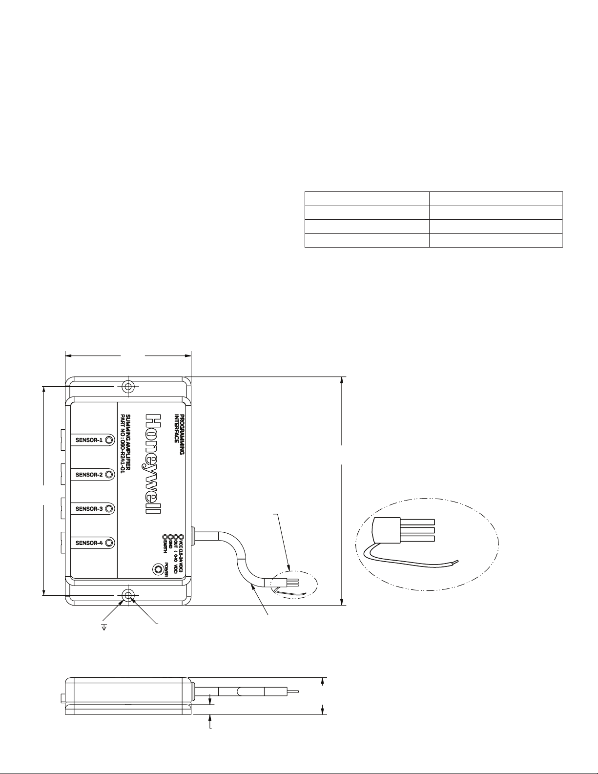
Honeywell’s Summing In-Line Amplifiers are housed in a small
plastic package, which is connected between the transducer
and a readout instrument/UI running on a computer or laptop.
The Summing In-Line Amplifier supplies a regulated bridge
MOUNTING DIMENSIONS mm [in]
008-0749-00
excitation voltage for the transducer and converts the millivolt
signal from the transducer to a 0-10 Vdc amplified signal. The
Summing In-Line Amplifier features include auto excitation
voltages, programmable gain settings, and a wide adjustment
range on the Span and offset value.
1.2 | Product Specifications
Power Requirements 15 Vdc to 24 Vdc
Output Voltage 0 Vdc to 10 Vdc
Accuracy ±0.25 % full scale span (FSS)
Operating Temperature Range -10 °C to 60 °C [14 °F to 140 °F]
[4.6]
2 X Ø 7,0
[0.3]
3,0
[0.1]
[2.8]
2 X Ø 4,0
[0.1]
THRU
SEE DETAIL A
26 GA TWISTED LEADS
TEFLON INSULATED
0,91 m length – cable
[3 ft length – cable]
127,0
[5.0]
EARTH
(SHIELD)
DETAIL A
VCC
OUTPUT
GND
GREEN
RED
WHITE
BLACK
6,0
21,0
[0.8]
Sensing and Internet of Things 1
Page 4
Installation and Technical Manual for the
ISSUE A
Summing In-Line Amplifier, Order Code AA919
2 | MODULE DETAILS
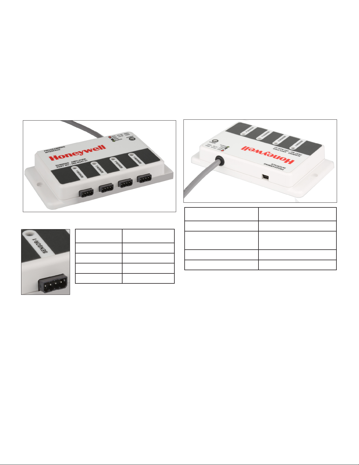
2.1 | External Connections - Sensor’s Side
The front view below shows the connections for the 4 sensors
to be connected to the Summing In-Line Amplifier. There are 4
mating connectors provided.
Figure 2.1a. External Connections
2.2 | External Connections - Rear Side
The rear view below shows the power input cable, as well as the
USB mini connector for Programming interface to connect the
Summing In-Line Amplifier to host PC.
008-0749-00
Figure 2.2. External Connections - Cable and Mini
USB
Figure 2.1b. External Connector Pinout
Pin Number Connection
1 + Vexc
2 -Signal
3 + Signal
4 -Vexc/Gnd
pin 1 2 3 4
Note: Pin numbers are in the same order for all: Sensor-1, Sensor-2, Sensor-3, Sensor-4.:
Cable Wire Color Connection
Red (+) Supply
Black Supply Return /
(-) Output
White (+) Output
Green Earth
• The Summing In-Line Amplifier can be powered from a
15-24V DC power supply.
• The power cable used for the Summing In-Line Amplifier
is shielded 4 core cable. There are 4 conductors available
for the connections.
Note: Green Wire is connected to the Shield of the cable
Note Mini USB connector is used to configure the sensor’s
using the host PC/Laptop
2 sensing.honeywell.com
Page 5
Installation and Technical Manual for the
ISSUE A
Summing In-Line Amplifier, Order Code AA919
3 | OPERATING GUIDE
3.1 | Installation of Software and Drivers
The Summing In-Line Amplifier requires installation of the
Desktop Application and accompanying software drivers.
Please follow these instructions to obtain and load the software
on a compatible PC or laptop.
Before installing, be sure to remove any earlier versions by
using the Uninstall programs feature on your computer.
3.1.1 | System Requirements
• Operating System – Windows 7 or Windows 10, 32 & 64
bits
• The screen must support and be set for a resolution of 800
x 600 or higher
3.1.2 | Loading Software and Device Drivers
1. Download the required Summing In-Line Amplifier Software and Device Drivers from the following URL:
https://sensing.honeywell.com/test-measurementproducts/summing-amplifiers/aa919
2. Unzip the downloaded file to a location on your computer
or laptop.
008-0749-00
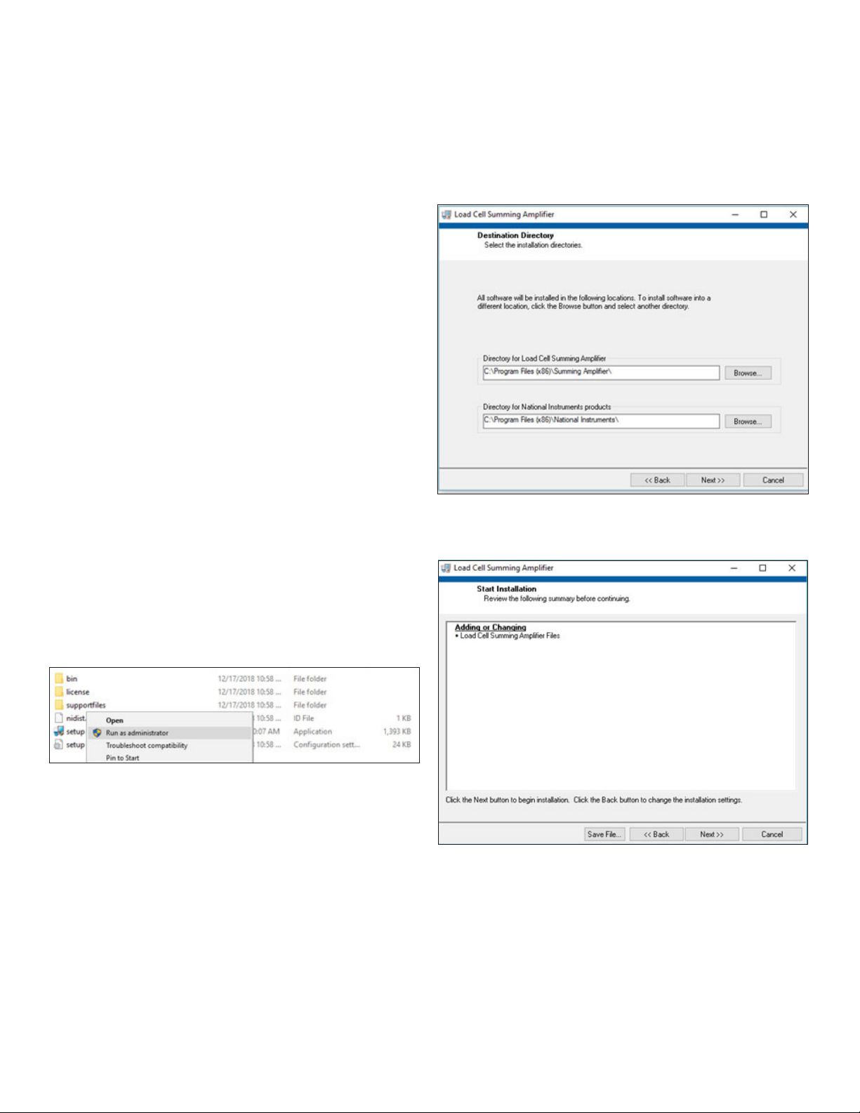
4. Select the directory for the installation and click the Next
Button.
Figure 3.1.2b. Identify Installation Directory
5. Review the details and click Next.
Figure 3.1.2c. Continue Installation
3. Navigate to that location and run Setup.exe by right-clicking the file and selecting Run as administrator.
Figure 3.1.2a. Start Setup.exe in Administrator Mode
Sensing and Internet of Things 3
Page 6

Installation and Technical Manual for the
ISSUE A
Summing In-Line Amplifier, Order Code AA919
6. When you see Installation Complete, click the Next button.
Figure 3.1.2d Desktop Application Install Completes
008-0749-00
8. After extraction, click Next to continue with the Device
Driver installation.
Figure 3.1.2f. Device Driver Welcome Screen
7. Install the Future Technology Devices International (FTDI)
Combined Driver Model (CDM) drivers. Click on the Extract
button.
Figure 3.1.2e. FTDI CDM Driver Installation
9. Accept the agreement by selecting the radio button, and
click Next.
Figure 3.1.2g. Device Driver License Agreement
4 sensing.honeywell.com
Page 7

Installation and Technical Manual for the
ISSUE A
Summing In-Line Amplifier, Order Code AA919
10. Allow the Device Driver installation to run. Drivers will display as Ready to use when installation is complete, .
Figure 3.1.2h. Device Driver Installation Completion
008-0749-00
3.3 | Connect Amplifier to PC and Launch
Desktop Application
3.3.1 | Connect Mini USB cable
1. Connect the smaller end of the provided Mini USB cable to
the port on the rear of the Summing In-Line Amplifier as
shown in 2.2. Then connect the larger end of the mini USB
cable to a USB port on the computer..
2. Launch the Load Cell Summing In-Line Amplifier desktop
application on the PC.
Figure 3.3.1a. Honeywell Splash Screen (momentarily
shown)
3.2 | Making the Connections
3.2.1 | Connect Amplifier to Power
Refer to 1.3 and 2.2 to properly connect and apply power to the
Summing In-Line Amplifier.
When you apply power to the Summing In-Line Amplifier, the
POWER LED on the front of the device will glow green. The four
sensor LEDs will blink red.
3.2.2 | Connect the Sensors
Refer to 2.1 to properly connect required sensors to amplifier
ports. Up to four sensors can be connected.
As sensors are connected, accompanying port LEDs on the
front of the amplifier will glow green.
3. Select the appropriate Communication Port from the drop
down. You can verify port availability by opening Device
Manager> Ports(COM & LPT), then select the correct port
from the dropdown.
Figure 3.3.1b. Select Communication Port
4. Click Connect. When the connection is complete the simulated LED on the Connect button will glow green as shown
in “Figure 3.3.1b. Select Communication Port”
Sensing and Internet of Things 5
Page 8

Installation and Technical Manual for the
ISSUE A
Summing In-Line Amplifier, Order Code AA919
3.4 | Output Scaling
1. Click on the Output Scaling button on the application
interface that should now be active.
Figure 3.4a. Output Scaling Option
008-0749-00
4. Click on the Output Scale button to apply the changes
back to the amplifier. The application interface asks for
verification first.
Figure 3.4c. Verify Output Scaling Changes
5. Click OK to continue.
Note:
• The Sensivity should be within the Range of 1.5 mV/V-12
mV/V. You will see a warning if the value is out of range.
• Zero Output should be within ± 10 % of FS. You will see a
warning if the value is out of range.
2. The user interface reads the default configuration values
from the Summing In-Line Amplifier and displays them.
3. Modify desired values based on calibration sheets provided by the sensor manufacturers. Fields available include
product serial number, sensitivity in mV/V, and zero output
of the sensor from the calibration sheet. Zero output has to
be entered as % of FS.
Figure 3.4b Output Scaling User Interface
6 sensing.honeywell.com
Page 9

Installation and Technical Manual for the
ISSUE A
Summing In-Line Amplifier, Order Code AA919
3.5 | Save Configuration
1. To save the configuration to the PC/laptop, click on the
Save button.
Figure 3.5a. Save Configuration Option
2. Select the desired directory path and provide a file name.
Then click Apply, and the interface will validate the save.
Figure 3.5b. Saving - Provide Path and File Name
008-0749-00
3.6 | Load Configuration
1. To load a configuration previously saved to the PC/laptop
into the user interface, then to the amplifier, click on the
Load button.
Figure 3.6a. Load Configuration Option
2. Select the path and file, and click on the Load Settings
button to load the settings into the user interface.
Figure 3.6b. Load Configuration Option
3. Click on the Output Scale button to apply the settings to
the amplifier.
Figure 3.6c. Apply Settings to Device
4. Verify that the settings were loaded into the amplifier by
clicking Read From Device.
Figure 3.6d. Read from Device Option
5. Exit Output Scaling by clicking on Exit.
Figure 3.6e. Exit Output Scaling Option
Sensing and Internet of Things 7
Page 10

Installation and Technical Manual for the
ISSUE A
Summing In-Line Amplifier, Order Code AA919
3.7 | Tare and UnTare
1. The Tare function is useful in zeroing the preload on setup.
Click the Tare button to load Zero Value to the amplifier.
Note: Tare limit is 30% of FS. When the preload of load on the
amplifier is more than 30% of FS, Tare command will show an
error.
Figure 3.7a. Tare Option
008-0749-00
Figure 3.7c. UnTare Option
1. After UnTare, the output will return to original values..
Figure 3.7d. UnTare Results
2. Click Yes to continue with the Tare function.
Figure 3.7b Tare Validation
3. The Output Voltage is now set close to zero and the values
are saved to flash memory on the Summing In-Line Amplifier.
4. Tared output can be reversed by clicking on the UnTare
button.
8 sensing.honeywell.com
Page 11

Installation and Technical Manual for the
ISSUE A
Summing In-Line Amplifier, Order Code AA919
3.8 | Shunt Calibration
1. An electrical signal equivalent to that produced by a known
load can be obtained by activating the Shunt Calibration
function.
The Shunt Calibration function is achieved by connecting
a high-precision resistor of known value, in parallel (shunt)
with one arm of the strain gage Wheatstone bridge. The
connection is made by a solid-state switch, which will be
activated by the Shunt Cal ON button.
In the Summing In-Line Amplifier, a fixed resistor with resistance of 61900 Ohms is used as the shunt resistor. The
output of the Summing In-Line Amplifier during Shunt Cal
ON depends on the bridge resistance and sensitivity of the
sensor connected to the amplifier.
When a Sensor with the 350 Ohm Bridge resistance and
2.0mV/V sensitivity is connected to the amplifier, the
output of the amplifier will saturate to ~70% of full scale
during the shunt calibration.
Table 3.8a. Shunt calibration Output vs Bridge resistance & Sensitivity
008-0749-00
Figure 3.8a. Shunt Cal ON Option
1. Observe the output.
Figure 3.8b. Shunt Cal ON Output
SL No Bridge resistance
1 350 2 70%
2 350 4 35%
3 350 10 14%
4 700 10 28.2%
Shunt Cal On Output = (0.000004286* Bridge Resistance) *100
(Sensitivity)
Example:
Consider Sensor with Bridge resistance of 700 Ohm & Sensitivity 10mV/V
Shunt Cal On Output = 0.000004286 * 700*100 = 28.2% of Full Scale = 2.82V
0.010
of Sensor in Ohms
Output of the Summing In-Line Amplifier under shunt
calibration for any other values of the bridge resistance and
sensitivity can be calculated using this equation:
Sensivity
In mV/V
% of Full Scale Output of
Summing In-Line Amplier
when Shunt Cal ON
2. Turn off shunt calibration by clicking the Shunt Cal OFF
button:
Figure 3.8c Shunt Cal OFF Option3.9 | Other Options
3.9 | Disconnect Option
1. To disconnect the device from the PC/laptop, click on the
Disconnect button.
Figure 3.9. Disconnect Option
Sensing and Internet of Things 9
Page 12

Installation and Technical Manual for the
ISSUE A
Summing In-Line Amplifier, Order Code AA919
4 | WARNING & ERROR MESSAGES
4.1 | Output Scaling
The Sensitivity should be within the Range of 1.5mV/V -12mV/
V. The user interface will pop up a warning when it is out of
range
Figure 4.1. Sensivity Out of Range
008-0749-00
4.2 | Taring with More Than 30 % Load
The amplifier will allow Taring off 30 % of FS preload of the
system.
Taring off with more than 30 % delivers an error message.
Here is an example.
Figure 4.2a. Tare Weight Limit Crossed
• If the entered value is more than 12, a default value of 12
mV/V will be used.
• If the entered value is less than 1.5, a default value of 1.5
mV/V will be used.
Similarily, the Value of Zero output should be within the range
of ± 10 % FSS.
Because the example shows 50 % of load applied, the device
would pop up a warning message.
10 sensing.honeywell.com
Page 13

Installation and Technical Manual for the
ISSUE A
Summing In-Line Amplifier, Order Code AA919
Here is an example showing a successful Tare using 25 % load
on Sensor 1.
Figure 4.2b. Successful Tare
The Output also shows appropriate value in a successful Tare..
008-0749-00
5 | DIAGNOSTIC FEATURES
The amplifier’s sensor LED indicators glow red or green depending on whether a sensor is connected to the amplifier port.
Under normal operating conditions with four sensors connected to the amplifier, all four LEDs will glow green.
1. When sensors are not conencted to an amplifier port, the
LED for that port will glow red instead of green. Likewise
when the amplifier is connected to a PC/laptop with the
desktop application running, the sensor displays will also
glow green or red.
Figure 5. Sensor LED and Desktop Interface
In this example you see that sensors 3 and 4 are not
connected and glowing red on the amplifier and the user
interface.
2. A red indicator can also mean the sensor is faulty, a bridge
is open, or shorted out.
3. A red indicator also indicates a sensor is loaded more than
110 % of FS.
Example: When the load on an individual sensor is more
than 110 % of FS, the LED will blink red to indicate potential overload of the sensor.
Sensing and Internet of Things 11
Page 14

Installation and Technical Manual for the
ISSUE A
Summing In-Line Amplifier, Order Code AA919
WARRANTY/REMEDY
Honeywell warrants goods of its manufacture as being free
of defective materials and faulty workmanship. Honeywell’s
standard product warranty applies unless agreed to otherwise
by Honeywell in writing; please refer to your order acknowledgement or consult your local sales office for specific warranty details. If warranted goods are returned to Honeywell
during the period of coverage, Honeywell will repair or replace,
at its option, without charge those items that Honeywell, in its
sole discretion, finds defective. The foregoing is buyer’s sole
remedy and is in lieu of all other warranties, expressed or
implied, including those of merchantability and fitness for a
particular purpose. In no event shall Honeywell be liable for
consequential, special, or indirect damages.
While Honeywell may provide application assistance personally,
through our literature and the Honeywell web site, it is customer’s sole responsibility to determine the suitability of the
product in the application.
Specifications may change without notice. The information we
supply is believed to be accurate and reliable as of this printing.
However, Honeywell assumes no responsibility for its use.
008-0749-00
Notices and Trademarks
While this information is presented in good faith and believed
to be accurate, Honeywell disclaims the implied warranties of
merchantability and fitness for a particular purpose and makes
no express warranties except as may be stated in its written
agreement with and for its customers.
In no event is Honeywell liable to anyone for any indirect, special or consequential damages. The information and specifications in this document are subject to change without notice.
Honeywell is a registered trademarks of Honeywell International Inc.
Other brand or product names are trademarks of their respective owners.
For more information
Honeywell Sensing and Internet of
Things services its customers through a
worldwide network of sales offices and
distributors. For application assistance,
current specifications, pricing or the
nearest Authorized Distributor, visit
sensing.honeywell.com or call:
Asia Pacific +65 6355-2828
Europe +44 (0) 1698 481481
USA/Canada +1-800-537-6945
Honeywell Sensing and Internet of Things
9680 Old Bailes Road
Fort Mill, SC 29707
www. honeywell.com
COAX-SEAL® is the registered trademark of Universal Electronics.
Scotch® is the registered trademark of 3M.
EthernNet/IP® is the registered trademark of ODVA, Inc.
008-0749-00-A-EN | 1 | 06/19
© 2019 Honeywell International Inc. All rights reserved.
 Loading...