

Page 1

VALVE PROVING SYSTEM
PRODUCTHANDBOOK
A4021 Series
UNIVERSAL GAS VALVES
EN2R--9023 9705R0--NE
APPLICATION
The A4021 is a self--checking microprocessor based Valve
Proving System (VPS). The A4021 checks the effective closure of automatic shut--off valves by measuring the pressure
differential between two valves during the test sequence.
Subbase and pressure switch are required to complete the
system.
When during the test sequence of the A4021 a failing valve is
detected, the A4021 will go into a non--volatile lock--out status, generates an alarm and prevents a burner start--up.
The intended application is for gas fired power burners and
other large capacity gas firing installations,whereaccording
to the European norm EN676 a valve proving system can be
used as an alternative for pre--purging the combustion chamber. And for installations with or without pre--purge with a
capacity of more than 1200 kW.
Subject to change without notice. Printed in the Netherlands.
Page 2

L
CONTENTS
Application 1................................................................
General 2....................................................................
Application (continued) 2.....................................................................
Features 3...................................................................
Description 4................................................................
Working principle 4..........................................................................
Specifications 7.............................................................
Mechanical 7...............................................................................
Electrical 7.................................................................................
Functional 7................................................................................
Dimensional drawings 9......................................................
Safety Provisions 10..........................................................
Energizing valve 1 and 2 10...................................................................
Use of terminal 12 10.........................................................................
Fail--safe relay drivers 10......................................................................
Anti--recycle--counter 10.......................................................................
Calculations 11...............................................................
General 11..................................................................................
Calculation examples 11.......................................................................
Installation and wiring 12......................................................
Installation 12................................................................................
Mounting Wiring Subbase 12...................................................................
Wiring 12....................................................................................
General considerations 12.....................................................................
Wiring 12....................................................................................
Pressure switch 12...........................................................................
General wiring diag rams 13....................................................
Applications with EC7850 14..................................................
Checkout 17..................................................................
Final checkout of the installation 17.............................................................
Troubleshooting 18...........................................................
Standards and Approvals 19...................................................
Ordering information 20.......................................................
Page 3
2
EN2R--9023 9705R0--NE
GENERAL
Application (continued)
The A4021A can be used for both single and combination
valves with or without pilot valve.
For valves with large nominal sizes, valve proving is possible
by use of auxiliary valves (pre--con figu ratio n only, see page 4).
For mounting the A4021 on a typical combination valve as the
VQ400 Series or on a large valve like the VE5000 Series
there is a mounting bracket available (order separately)
According the European standard EN676 a valve proving
system can be used under certain conditions,as an
alternative for pre--purging the combustion chamber.EN676
prescribes a valve proving system for capacity rating over
1,200 kW, see Table 1.
Table 1. Application valve proving systems according EN676
Heat--Input
With Pre--Purge Without Pre--Purge
p
[kW]
Main Gas Start Gas Main Gas Start Gas
[kW
]
≤ 10% ≥ 10% ≤ 10% ≥ 10%
≤ 70 2xB B*) 2xB 2xAor
2 x B +VPS
A**) 2xA
>70,≤ 1200 2xA 2xA 2xA 2xA+VPS 2xA 2xA
>1200 2 x A + VPS 2xA 2xA 2xA+VPS 2xA 2xA
NOTE: A: Automatic shut--offvalve approved on EN161, class A
B: Automatic shut--off valve approved on EN161, class B
Valve Proving System required
Valve Proving System as alternative for pre--purge of the combustion chamber
*) For third family gases: two class B valves are required
**) For third family gases: two class A valves are required
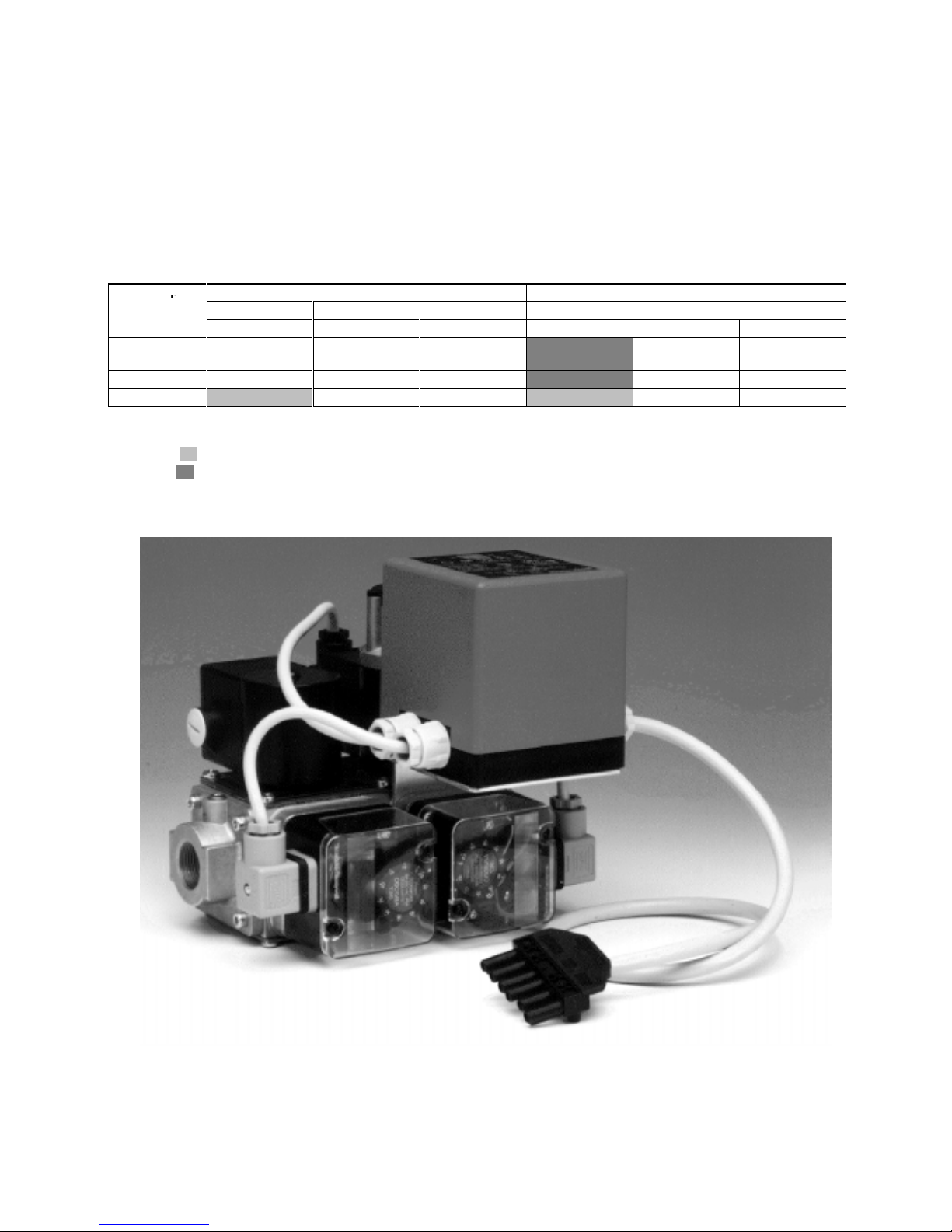
Fig. 1. VQ400 combination valve with A4021 valve proving System.
Page 4

3
EN2R--9023 9705R0--NE
FEATURES
• Microprocessor technology
• Based on 7800 SERIES Burner Programmer safety
technology
.
− Dynamic relay test
− Safe start test
− Self--diagnostic test
• Testing independent of type of gas at any inlet
pressure.
• Valve proving done by using the line pressure of the
gas.
• Non--volatile lockout.
• Automatic valve proving before heat demand, after
heat--demand or during pre--purge possible.
• Different test--times (per valve) available by different
O.S. numbers.
• Clear visual indication of the test sequence and
faults--causes through 5 LEDs.
• Storage of fault code when line interruption occurs
• Can be applied in all common valve configurations
• 2--wire gas pressure switch.
• Output for external alarm signal.
• Optional external remote reset.
Page 5
4
EN2R--9023 9705R0--NE
DESCRIPTION
The A4021 valve proving system checks the effectiveclosure
of the valves
before
burner start--up (pre--configuration) or
at
the end of
a heat demand (post--configuration). The
configuration can be set by means of wiring the A4021 in two
differentways, see Fig. 2. and 3.
The flow chart (Fig. 5. ) and sequence diagram (Fig. 6. )
explain the procedure during the valve proving.
An external pressure switch monitors the pressure between
both valves. The pressure switch must be set to half the inlet
pressure in order to test both valves with the same sensitivity.
After a short interruption of the mains supply during valve
proving or during RUN, the A4021 restarts automatically.
The A4021 valve proving system can be used with several
pilot--valve configurations,like intermittentand interrupted
pilot systems and 3--valve configurations as well.
14
9
L
12
A4021
ignition
controller
H.D
LGPS
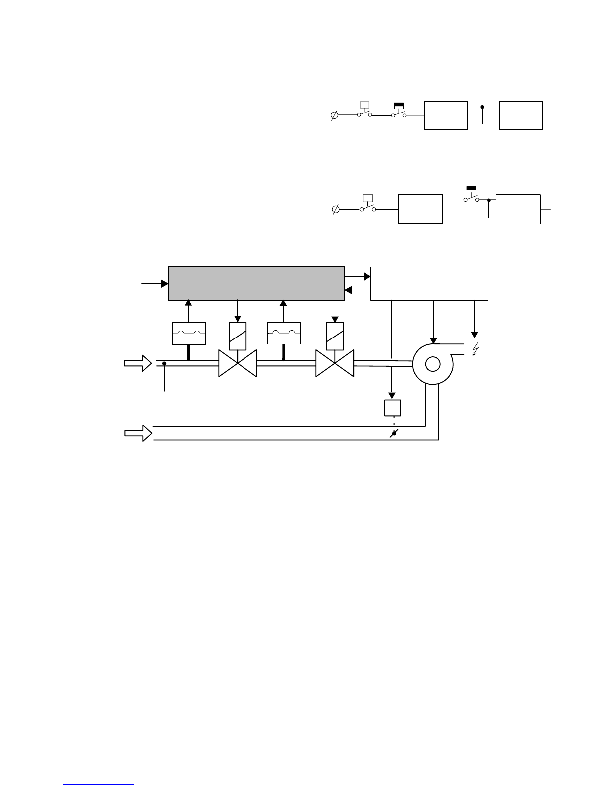
Fig. 2. Valve proving
pre--configuration
.
14
9
L
12
A4021
ignition
controller
LGPS
H.D
Fig. 3. Valve proving
post--configuration
.
V1
V2
heat
demand
burner
Pinlet
Pinlet
2
L.G.P .S.
G.P.S.
gas
air
Servo Motor MT4000 Series
Combi--valveVQ400 Series
ValveProving System
A4021 Series
burner--controller
7800 SERIES
Gas pressure switches
C6058A Series
Fig. 4. System set--up .
Working principle
The A4021 valve proving system is based on the pressure
status--principle. This means that the valves are checked by
means of measuring (on/off) the pressure in the gas--pipe
between the two safety--valves. This system will only work
when there is sufficient gas--pressure (line--pressure).
Therefore a Low Gas Pressure Switch (LGPS) is part of the
installation. When the line--pressure (Pinlet) is too low the
LGPS will disable the valve proving system.
The section between the two valves is filled with gas
(high--pressure status) by opening valve--1(upstream valve)
and the pipe is emptied (low--pressure status) by closing
valve--1 and opening valve--2 (down--stream). When one of
the valves is l eaking this will mean that either the pressure
will not maintain the high--pressure status or the low--pressure
status at the end of the test period.
For this method of testing, the test time is a function of three
parameters.
− inlet pressure
− volume between the valves.
− maximum burner capacity.
The test time can be calculated as given on page11. Different
test times are available by different O.S. numbers.
Page 6
5
EN2R--9023 9705R0--NE
stabilization
time (3 sec.)
pressure
=low?
open valve 2
(5 sec.)
wait
(22 sec.)
open valve 1
(5 sec.)
pressure
=low?
stabilization
time (3 sec.)
pressure
=high?
wait
(22 sec.)
pressure
=high?
enable
ignition
controller
error + lock--out
no
no
no
no
yes
yes
yes
yes
test valve 1
test valve 2
self test
=OK?
yes
no
manual reset
1
2
3
4
5
6
7
8
10
11
12
13
pin 12
connected
enable
ignition
controller
yes
?
self test
=OK?
each 4 hours
no
no
yes
14
15
15
STANDBY
RUN
0
9
start
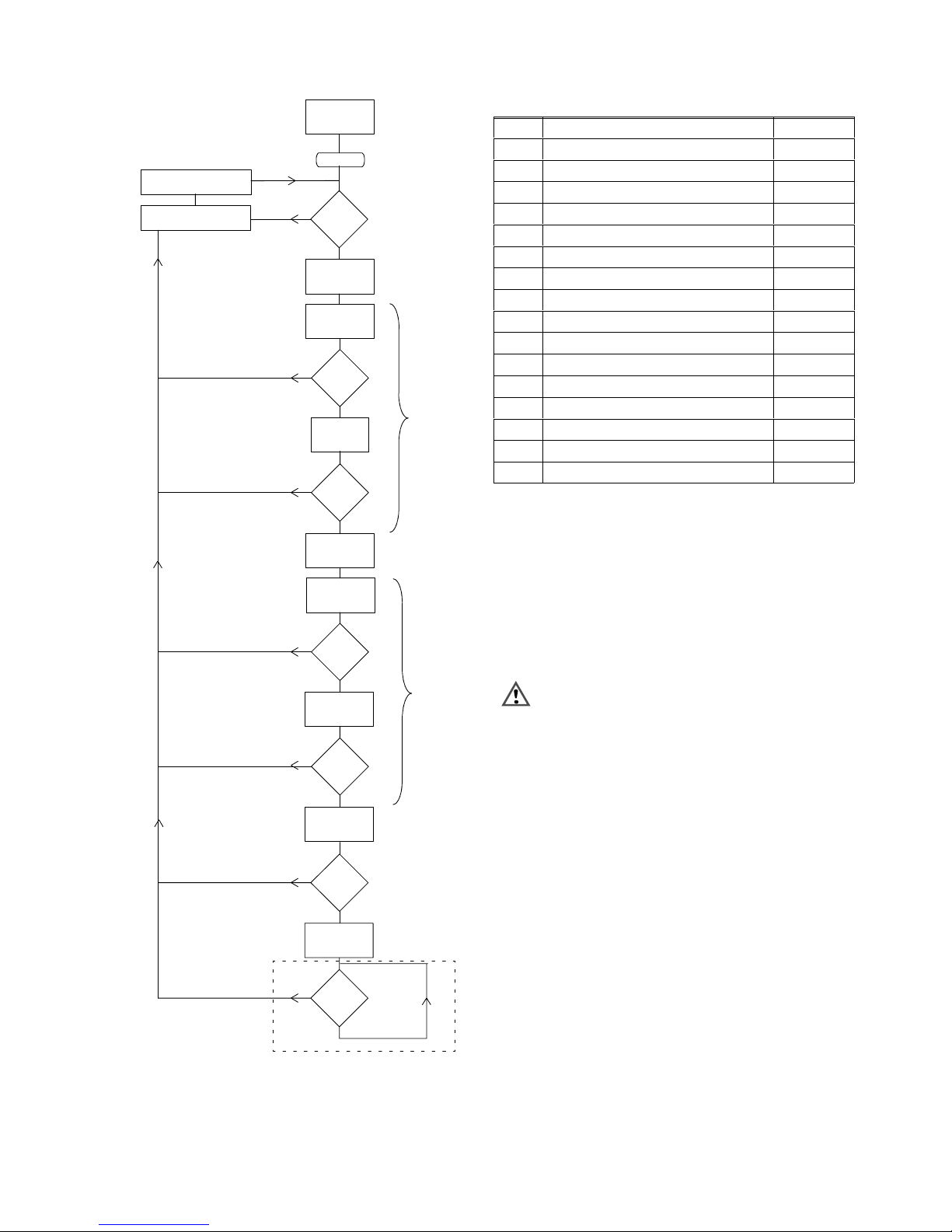
Fig. 5. General flow chart valve proving (given timings
for A4021A1002/1010
Table 2. Sequence timings for normal operation
State
Description Time1)(s)
0 STANBY infinite
2)
1 self--test + memory test <2
2 V2 powered 5
3 waiting for pressure to get low 3
4 wait 22
5 valve 1 powered 5
6 waiting for pressure to get high 3
7 wait 22
8 waiting for ignition controller to start indefinite
3)
9 RUN period, every 4 hours self--test
10 alarm, “error during test valve 1” indefinite
11 alarm, “valve 1 failing/leaking”
5)
indefinite
12 alarm, “error during test valve 2” indefinite
13 alarm, “valve 2 failing/leaking”
5)
indefinite
14 alarm, “error heat demand” indefinite
15 alarm, “self--test error”
4)
indefinite
1)
Timingsdepending on O.S. numbers, shown
A4021A1002/1010
2)
STANDBY can be infinite time period
3)
Depending on pre--purge and start--up time of the used
ignition controller
4)
When during the test sequence a fault is discovered by the
A4021, the system will go into a non- -volatile lock--out and
generate an alarm “self test error” (see also
Troubleshooting section).The “self test error” also occurs
when the anti--recycle--counter reaches the value 10, see
also page 10 of the Product handbook.
5)
Leakage ≥ 0.1 % of maximum flow rate.
WARNING
No standard valve proving after lock--outof the
ignition controller.
Valve proving after lockout maybe required, this can
be achieved by special wiring diagrams. E.g. when a
DTSP switch is used to reset the ignition controller
and interrupting the heat--demand for the A4021A.
Page 7

Heat demand
Line voltage
Lock--out
(Ignition controller)
Reset ign. control.
power--up start
heat--demand
end
heat--demand
lock-- outstart
heat--demand
reset
burner controller
Leak test
GPS
Valve V1
Vent valve
(normally open)
Valve V2
Leak test
GPS
Valve V1
Vent valve
(normally open)
Valve V2
PRE
POST
CONFIG
CONFIG
start whithoutvalve proving !
Fig. 6. Systemsequence of A4021A inpost and pre--configuration.
6 EN2R--9023 9705R0--N
E
Page 8

7
EN2R--9023 9705R0--NE
SPECIFICATIONS
Mechanical
Model
A4021A
Dimensions
Refer to Fig. 7.
For mounting bracket dimensions refer to Fig. 8.
Weight
Including subbase: 0.65 Kg
Mounting
ZL030001 subbase.
The subbase can be assembled by 2 screws on a panel.The
cover can be removed by loosening one screw. For mounting
hole dimensions see Fig. 7. installation drawing.
Orientation
There are no restrictions in the orientation.
Environmental ratings
Ambient temperature range:
Operating :- -10 ... 60 °C
Storage :--40 ... 80 °C
Humidity: :0 -- 95% RH at 40 °C (non--condensing)
Vibration :0.5 G environment
Electrical
Supply voltage
Line voltage: 220 ... 240 Vac, 50 Hz
100 ... 120 Vac, 50 Hz
Refer to Table 3.
Other voltage ranges and frequencies are available on
request.
Fusing
The A4021A should be externally fused to prevent damage to
the valve proving system, wiring or peripherals
External fuse: 16 A slow max.
Internal fuse: 5 A slow max.
Power consumption
Maximum 4.5 VA
Electrical ratings
Valve outputs: 4A, cos. ϕ 0.7
Vent valve output: 1A, cos. ϕ 0.7
Ignition controller output: 4A, cos. ϕ0.7
Alarm output: 2A, cos. ϕ 0.7
Electricalconnection
4WiringconduitaccordingtoPG11areprovidedinthe
subbase. M3.5 screw terminals, including earth connection.
Enclosure
IP40
Functional
Fieldadjustments (calibration)
None
Test--times
Depending on O.S. number.
For A4021A1002 and A4021A1010 per valve: 25 s.
Other test times available on request.
Totaltest--time (depending on test time per valve)
For model A4021002 and A4021A1010: approx. 65 seconds
Reset
NON--volatile lock--out
Manual, with push--button on controller or with remote reset
button.
Design life
> 10 years or 250.000 cycles.
Recommendedpressure switch
C6058A gas pressure switch
Page 9

8
EN2R--9023 9705R0--NE
Table 3. Connections for A4021A pre-- and post configuration with contact ratings
Terminal
Abbreviations
Direction Description Ratings
N
o.
pre post
(22
0
...
240
Vac/10
0
...
120
V
ac,
depending on O.S. number)
1 NO NO input Normally Open contact of the pressure
switch (high pressure)
n.a.
2 RESET RESET input Inputfor external reset connect with
momentary switch to line
n.a.
3 LINE LINE power--input Line voltage input for v alve proving
system.
n.a.
4 N N power--input Neutral input for valve proving system. n.a.
5 N N power Neutral for external devices. n.a.
6 N N power Neutral for external devices. n.a.
7 V2--IN V2--IN input Valve--2 voltage from ignition controller n.a.
8 V2--OUT V2--OUT output Output connect with Valve--2 4A
9 HD LGPS input Heat--demand input (pre--configuration)
or LGPS input (post--configuration)
n.a.
10 ALARM ALARM input Alarm input 4A
11 ALARM ALARM output Alarm output 2A
12 RB RB input Read back signal for: heat- -demand
(post-- config.) ign. contr. (pre--config.)
4A
13 VENT VENT output Normally open valve output 1A
14 IGNCTR HD output Heat call signal to ignition controller,
when there is a heat call and the valve
proving has taken place
4A
15 V1--IN V1--IN input Valve--1 voltage from ignition controller 2A
16 V1--OUT V1--OUT output Output connect with Valve--1 4A
NOTE: cos. ϕ = 0.7 for all outputs
Page 10

9
EN2R--9023 9705R0--NE
DIMENSIONAL DRAWINGS
97
35
67543218
9 10111213141516
16
PG11
88
97
Fig. 7. Mounting dimensions of A4021A and subbase in millimeters
74.5
80
96
60.5
80
96
8.5
34.5
86.5
52
69
∅ 4.5 (4x)
3
90°
103
∅ 20
Fig. 8. Mounting bracket A4021A for VQ400 and VE5000 Series in millimeters.
Page 11

10
EN2R--9023 9705R0--NE
SAFETY PROVISIONS
15
8
16
A4021A
12
13
= input micro--processor
LGPS
H.D.
valve--1
valve--2
14
burner controller
V2 V1
H.D.
input out
vent- - valve
external reset
2
L
11
alarm
6
N
int. power supply
H.D.
post--config.
post--config
pre--config.
1
GPS
9
3
4
10
5
7
pre--config.
fuse
16A
N
= external wiring
= optional
internal fuse
5Aslow
Fig. 9. Simplified internal schematic and wiring diagram pre-- and post--test configuration.
Energizing valve 1 and 2
The hardware of the A4021A prevents that during the valve
proving both valves can be opened at the same time.
Use of terminal 12
With terminal 12 of the valve proving system the heat demand
status is checked by the valve proving system in post
configuration. For the pre--configuration it is necessary that
terminal 12 and14 are connected.
If terminal 12 is not connected, the A4021A will raise an alarm
(error heat demand).
Fail--safe relay drivers
The fail--safe relay drivers which are used to give the
heat--demand to the burner controller are fail safe.
Anti--recycle--counter
For reason that during each valve proving a small amount of
gas enters the combustion chamber, extra safety provisions
are build in to prevent the A4021A from continuously
recycling, in case of failures of the complete burner control
system. This safety feature is provided by an anti--recycling
counter in the A4021A. When the heat--demand signal
disappears during a valve proving or within 10 seconds, after
the valve--proving is finished. This leads to lockout (error
self--test) of the A4021A when this behavior occurs 10 times
in a row. The counter will be reset by the first heat--demand
which lasts longer than the A4021A total--test time + 10
seconds. In this way the A4021A offers additional safety.
Page 12

11
EN2R--9023 9705R0--NE
CALCULATIONS
General
The maximum allowable leak--rate (according the EN676 and
EN746--2) is 0,1 % of the maximum burner capacity. The test
time necessary to detect a falling valve is a function of:
− inlet pressure
− test volume
− burner capacity.
When the volume between two safety--valves is bigger it
takes more time (in case of a leaking valve) to change the
status of the gas pressure switch. The correct OS--number
for the A4021A can be selected after calculating the
appropriate test--times for the intended application.
The switching point of the pressure--switch is set to 50 % of
the maximum inlet pressure.
ThetestperiodTpiscalculatedfromtheinletpressurePi,the
test volume Vp ( see Table 4.) and maximum burner capacity
Qm, in formula:
Tp ≡
2xPixVp
Qm
[s]
Pi = inlet pressure [mbar]
Vp = test volume [ dm
3
],seealsoTable4.
Qm = burner capacity [dm
3
/h]
Table 4. Volumes in dm
3
for UGV valvesVpwith length of
pipe L (including V1 and V2)
DN
Length between valves (m)
0 0,5 1 1,5 2 per
extra
meter
10T 0.06 0.10 0.14 0.18 0.22 0.08
15T 0.06 0.15 0.24 0.33 0.42 0.18
20T 0.12 0.28 0.43 0.59 0.74 0.31
25T 0.19 0.44 0.68 0.93 1.2 0.49
32T 0.69 1.1 1.5 1.9 2.3 0.80
40T 0.71 1.4 2.0 2.7 3.3 1.3
50T 1.3 2.3 3.3 4.2 5.2 2.0
65T 2.7 4.4 6.0 7.7 9.3 3.3
80T 2.9 5.4 7.9 10 13 5
65F 3.2 4.9 7.5 8.2 9.8 3.3
80F 4.4 6.9 9.4 12 14 5.0
100F 6.5 10.5 14.4 18 22 7.9
NOTE: T=Thread
F=Flange
V
0m
= volume of 2 valves with L= 0 m
IMPORTANT
ThetotalvolumeVphastobecalculatedwithall
volumes between the tested valves: internal
volumes of valves and all pipes
Calculation examples
Example 1
Calculate the maximum pipe length between two 1 1/2” safety
valves when an A4021A valve proving system is used with a
test period (per valve) of 25 seconds.
Given: Pi = 75 mbar
Qm = 30 dm
3
/h
valve: 1 1/2”→DN40
To be calculated: L(max.) [m]
Calculation:
p ≡
2xPixVp
Qm
[s]
→
Vp ≡
Tp x Qm
2xPi
[dm
3
]
Vp ≡
25 x 30
2x75
[dm3]
=5
From Table 4. :
DN40T, Vp= 5 dm
3
→
length L = 2 + (5--3.3)/1.3 = 3.3 m.
Example 2
Calculate the test period (per valve) in a given situation.
Given: Pi = 150 mbar
Qm = 60 dm
3
/h
valve: VE4065A with 0.5 meter pipe
To be calculated: Tp [s]
Calculation:
From Table 4. :
DN65T, L=0.5m
→
Vp = V
0.5m =
4.4 dm3.
p ≡
2xPixVp
Qm
[s]
→
Tp ≡
2x150x4.4
60
=22[s]
Choose always a A40121 with a test time (per valve) higher
than the (minimum) calculated test time Tp.
Example 3
Calculate the test period (per valve) in given situation.
Given: Pi = 150 mbar
Qm = 100 dm
3
/h
valve: VE4080A with 1 meter pipe (L1)
pilotvalve:VE4025with0.5meterpipe(L2)
To be calculated: Tp [s]
Calculation:
From Table 4. :
DN80T, L1=1m
DN25T, L2=0.5
Vp = V
1m + (V0.5m --V0m =
7.9 + (0.44 -- 0.19/2) = 8.25 dm3.
p ≡
2xPixVp
Qm
[s]
→
Tp ≡
2x150x8.25
100
=25[s]
Choose always a A40121 with a test time (per valve) higher
than the (minimum) calculated test time Tp.
Page 13

12
EN2R--9023 9705R0--NE
INSTALLATION AND WIRING
Installation
IMPORTANT
1. Read these instructions carefully. Failure to follow
the intructions could damage the product or cause a
hazardous condition.
2. Before installing or replacing any control check that
the test time is correct for the application. Never use
a type with a smaller test time than the calculated
test time for the application.
3. Check the ratings given in the instructions and on
the product to make sure the product is suitable for
your application.
4. The installation has to be carried out by qualified.
personel only.
5. Carry out a thorough checkout when installation is.
completed.
Mounting Wiring Subbase
NOTE: For installation dimensions, see Fig. 7.
1. The subbase can be mounted in any position. Make
sure that the LEDs indicating the test sequence and
faults--causes are clearly visible.
2. Select a location within an electrical panel. Be sure to
allow adequate clearance for servicing, installation and
electrical field connections.
3. For surface mounting, use the back of the subbase as a
template to mark the two screw locations. Drill the pilot
holes.
4. Securely mount the subbase using two M3.5 x 0.6
screws.
Wiring
CAUTION
1. Disconnect power supply before beginning the
installationto prevent electrical shock, equipment
and control damage. More than one power supply
disconnect may be involved.
2. Wiring connections are for the A4021A are
unique, therefore, refer to Table 3. and Fig. 7. for
proper subbase wiring.
3. The A4021A must be installed with fixed wiring for
phase and neutral connections.
4. Wiring must comply with all applicable codes,
ordiances and regualtions.
5. After moving the A4021A valve proving system
from outdoor to indoor conditions, condensation
may occur. Do not connect condensated valve
proving system to mains.
6. The A4021A is not suitable for phase--phase
mains., can only be used with phase -- neutral
mains.
7. For each application diagram, local approval may
be needed
General considerations
There are two basic wiring diagrams:
• valve proving before burner start--up: pre--configuration.
• valve proving at end of heat demand: post--configuration.
Wiring
1. For proper subbase wiring, refer to Table 3.
2. Disconnect the power supply from the main disconnect
before beginning the installation to prevent electrical
shock and equipment damage. More than one
disconnect may be involved.
3. All wiring must comply with all applicable electrical
codes, ordnances and regulations.
4. Use the COM and NO contacts on both pressure
switches (LGPS and GPS).
5. Make sure loads do not exceed the terminal ratings.
refer to the label on the valve proving system, or to the
ratings in the Specifications, see Table 3.
6. Check the power supply circuit. the voltage and
frequency tolerance must match those of the valve
proving system. Add the required disconnect means
and overload protection.
7. Check all wiring circuits before installing the valve
proving system on the subbase
8. Install all electrical connectors.
9. Restore power to the panel.
Pressure switch
The pressure switch can be a normal normally open gas
pressure switch which is suitable for the appropriate pressure
levels and a voltage of 220 ... 240 Vac. Refer to the enclosed
instructions of the pressure switch. The switching point of the
GPS must be at 50 % of the nominal line--pressure.
Recommended gas pressure switch: C6058A
Page 14

13
EN2R--9023 9705R0--NE
GENERAL WIRING DIAGRAMS
LGPS GPS
Valve Proving System
A4021A
6(N)
V2
8
10
ALARM
vent--valve
11
13
15
Ignition controller
4(N)
N L
1
2
T
(ext.)
1214
heat- -demand
input
7
9
main--valve
output
V1
16 5(N)
reset
fuse
3
L
N
16A
Fig. 10. Wiring diagram for 2--valve configuration
pre--configuration
LGPS GPS
Valve Proving System
A4021A
6(N)
V2
8
10
ALARM
vent--valve
11
13
Ignition controller
4(N)
N L
1
2
(ext.)
1214
heat--demand
input
9
15 7
main--valve
output
V1
16 5(N)
reset
fuse
3
L
N
16A
T
Fig. 11. Wiring diagram 2--valve configuration for
post--configuration
LGPS GPS
Valve Proving System
A4021A
6(N)
V2
8
10
ALARM
vent--valve
11
13
Ignition controller
4(N)
N L
1
2
T
(ext.)
1214
heat--demand
input
9
15
main
output
V1
16 5(N)
reset
fuse
3
L
N
16A
Vp
7
pilot
output
valve
valve
Fig. 12. wiring diagram 3--valve configuration
(pre--configuration)
LGPS GPS
Valve Proving System
A4021A
6(N)
V2
8
10
ALARM
vent--valve
11
13
Ignition controller
4(N)
N L
1
2
(ext.)
heat--demand
input
9V116 5(N)
reset
fuse
3
L
N
16A
Vp
1214
T
15
main
7
pilot
output
valve
valve
output
Fig. 13. Wiring diagram 3--valve configuration
(post--configuration)
WARNING
These are general wiring diagram and have not been
approved yet by an officialapprovalbody. Depending
on the application and used ignition controller special
wiring diagrams maybe required.
Page 15

14
EN2R--9023 9705R0--NE
APPLICATIONS WITH EC7850
20
LINE
NEUTRAL
EC7850
N3AL4L15
FAN6RT7LD28PV19MV10IGN
F
flame-signal
G
ground
13
COM
12
HI
15
LOW
14
MOD
16
C.V.
18
ES1
17
ES2
19
ES3 LOS
21
PV222SHTR
EARTH
ALARM
(intermittent)(interrupted)
gas supply
V1 V2
H.D.
open atmosphere
vent-valve
L.G.P.S.
EXTERNAL
RESET
A4021A
GPS
9
V1INLGPS / HD10OUT11VENT
13 15
V1OUT
16
RBHD12HD--OUT
1432NO1 7
V2IN8V2OUT
4 5 6
NNN
ALARM
IN
RESET
LINEext.
burner
FAN
flame--rod
ign.
P.S.
lock--out switch
L.G.P.S.
Fig. 14. Wiring diagram A4021A- - EC7850 pre- -configuration: intermittent pilot and vent--valve to open atmosphere
13
LINE
NEUTRAL
EC7850
N3AL4
L15FAN
6RT7
LD28PV19MV
10
IGN
F
flame-signal
G
ground
13
COM
12
HI
15
LOW
14
MOD16C.V.
18
ES1
17
ES2
19
ES320LOS21PV222SHTR
EARTH
ALARM
FAN
flame--rod
H.D.
ign.
P.S .
(intermittent)(interrupted)
gas supply
V1 V2
PV2PV1
HI
LO
A4021A
GPS
9
V1INLGPS / HD10OUT
11
VENT
15
V1OUT
16
RBHD12HD--OUT
1432NO1 7
V2IN8V2OUT
4 5 6
NNN
ALARM
IN
RESET
LINEext.
EXTERNAL
RESET
lock--outswitch
L.G.P.S.
L.G.P.S.
Fig. 15. Wiring diagram A4021A -- EC7850: pre--configuration, intermittent pilot, 4--valve configuration
WARNING
These are general wiring diagram and have not been
approved yet by an official approval body. Depending
on the application and used ignition controller special
wiring diagrams maybe required.
Page 16

15
EN2R--9023 9705R0--NE
LINE
NEUTRAL
EC7850 with rectification amplifier
N3AL4L15
FAN6RT7LD28PV19MV10IGN
F
flame-signal
G
ground
13
COM
12
HI
15
LOW
14
MOD
16
C.V.
18
ES1
17
ES2
19
ES3
20
LOS21PV222SHTR
EARTH
ALARM
FAN
flame--rod
H.D.
ign.
P.S .
(intermittent)(interrupted)
A4021A
GPS
9
V1INLGPS / HD10OUT
11
VENT
13 15
V1OUT
16
RBHD12HD--OUT
1432NO1 7
V2IN8V2OUT
4 5 6
NNN
ALARM
IN
RESET
LINEext.
EXTERNAL
RESET
gas supply
V1 V2
PV
G.P.S.
HI
LO
Lock--outswitch
L.G.P.S.
Fig. 16. Wiring diagram A4021A -- EC7850, post--configuration: intermittent system with 3--valve configuration
LINE
NEUTRAL
EC7850
N3AL4L15
FAN6RT7LD28PV19MV10IGN
F
flame-signal
G
ground
13
COM
12
HI
15
LOW
14
MOD
16
C.V.
18
ES1
17
ES2
19
ES3
20
LOS21PV222SHTR
EARTH
ALARM
FAN
flame--rod
H.D.
ign.
P.S .
(intermittent)(interrupted)
A4021A
GPS
9
V1INLGPS / HD10OUT
11
VENT
13 15
V1OUT
16
RBHD12HD--OUT
1432NO1 7
V2IN8V2OUT
4 5 6
NNN
ALARM
IN
RESET
LINEext.
EXTERNAL
RESET
gas supply
V1 V2
HI
LO
By--passvalve
Vb
LOCK--OUTSwitch2--stage
L.G.P.S.
L.G.P.S.
Fig. 17. Wiring diagram A4021A-- EC7850 with by--pass valve, post configuration
WARNING
These are general wiring diagram and have not been
approved yet by an official approval body. Depending
on the application and used ignition controller special
wiring diagrams maybe required.
Page 17

Operate burner
Valve 1
Valve 2
Heat demand
Alarm
Valve 2
Power
Run
OK
Valve 1
Pressure
(between V1 and V2
Alarm output
Timings (sec.)
*= depends on OS #
ALARM MODE
ERROR
HEAT
V1
ERROR
5*
5*
TEST MODE
TEST
V1
V2
START
OPEN
TEST
V2
V1
OPEN
STANDBY
SELF
RUN MODE
OPERATE
BURNER
(valves operated by
ignition controller)
WAIT
START--UP
3*
3*
25 * 25 *
TEST
GPS
GPS
TEST
ERROR
SELF--
Modes
States
0 1 2 3 4 5 6 7 8 9 11 12 14 15
DEMAND
HIGH
TEST
STANDBY
Line voltage
TEST
LOW
FOR
O
P
E
R
A
T
I
O
N
Sequenceof operation
V2
ERROR
10
V2
13
FAILIN G/
LEAKING
V1
FAILING/
LEAKING
WARNING
No standard valve proving after lock--out of the ignition controller
= blinking LED= LED is off = LED on
16
EN2R--9023 9705R0--N
E
Page 18

17
EN2R--9023 9705R0--NE
CHECKOUT
The procedures described in this chapter are related to
A4021A. For adjustments on the other additional
functionalities(e.g. pressure switch), refer to the included
instruction sheet of the product in question in the package.
WARNING
Phase --neutral dependency
As the EARTH is not connected to the actual A4021A
(earth only connected to the sub--base), it is not
possible to detect whether the line and neutral are
correct connected on the A4021A.
Exchanged connection of the phase and neutral can
lead to hazardous situations, when a short--circuit in
one of the valve c onnections occurs. Therefore the
A4021A can only be used with fixed wiring for the
line--voltage connections. Make sure that phase and
neutral are connected as instructed in the Wiring
section.
Final checkout of the installation
Set the appliance in operation after any adjustment and
observe several complete cycles to ensure that all burner
components function correctly.
Make sure that phase and neutral are connected as
instructed in the Wiring section.
Page 19

18
EN2R--9023 9705R0--NE
TROUBLESHOOTING
CAUTION
1. Use utmost care while troubleshooting the
A4021A, line voltage is present on some of the
terminals when power is on.
2. Line voltage is present on the terminals when the
cover is removed. Make sure that the main power
supply is switched off before removing the cover.
3. The A4021A contains no serviceable parts. Any
attempt or replacement of parts ( except from
internal fuse) will affect the safety of this
deviceand is therefor not allowed.
General
IfyouencounteraerrororfailonV1orV2,refertothe
instruction sheet of the valve.
If you encounter other problems in the system, refer to the
Troubleshooting section in the instruction sheet for the
appropriate flame safeguard control.
Upon completion of troubleshooting, be sure to perform the
Checkout procedures previously specified for the A4021A.
NOTE: Instructions for replacing the cover and fuse are
given in the Service section.
Before making a replacement, make sure you have the
correct part (check its part number and voltage rating)
Table 5. Troubleshooting A4021A Series valve proving System
States
ALARM V2PWR RUN V1
OK
Alarm mode Cause Action
10 Error V2 V2 is damaged or V2 is
wrong/not connected
Check connections V2 and
if necessary replace V2
11 Failing/leakingV1 Allowed leak--rate (V1)
higher than 0.1% of the
maximum flow--rate
Check the gas pressure
switch (GPS) and if
needed replace V1
12 Error V1 V1 is damaged or V1 is
wrong/not connected
Check connections V1 and
if necessary replace V1
13 Failing/leakingV2 Allowed leak--rate (V2)
higher than 0.1% of the
maximum flow--rate
Check gas pressure switch
(GPS) and if needed
replace V2
14 Error heat demand Heat demand read--back
error .
Check if pin 12 on A4021A
is connected
15 Error self--test Internal
Hardware/Software error
Reset main supply,reset
A4021A; if error still
occurs: replace A4021A
=blinkingLED= LED is off = LED on
Page 20

19
EN2R--9023 9705R0--NE
STANDARDS AND APPROVALS
The product is designed according to the following standards:
− (Pr)EN1643
− ENV 1954
− EN 60730
− EN 60742
− EN 60529 (IP40)
Radio interference protection conform the standards:
− IEC 1000- -4--3 (ENV 50140) (immunity to radiation
emission)
− IEC 1000--4--6 (ENV 50141) (immunity to injected
currents)
− EN 50081--2 (emission industrial level)
− IEC 1000--4--2 (electrostatic discharges)
− IEC 1000--4--5 (surges)
− IEC 1000--4--11 (voltage interruptions and decreases
− IEC 1000--4--4 (fast transient bursts)
Standards and Approvals (summarized)
The A4021A Series Valve Pr oving System is conform with the
following EC directives:
• Gas Appliance Directive (90/396/EEC)
PIN: CE--0063AS1822
• Low Voltage Directive (73/23/EEC)
• Electro Magnetic Compatibility Directive (89/336/EEC)
Page 21

20
EN2R--9023 9705R0--NE
ORDERING INFORMATION
When ordering specify:
• Model number
• Voltage
Order separately:
• ZL030001 Subbase.
• C6058A pressure switch.
• 1030002020 Mounting bracket for VQ400/VE5000
• Replacement parts, if desired.
Table 6. Ordering information A4021A Series Valve Proving System.
O.S. Number Rated
Test time**
Power
Enclosure*
Functional description
Remarks
Voltage
(Vac)
per valve
(s)
Consump.
(W)
gas
pressure
switch
3--valve
config.
remote
reset
alarm
output
A4021A1002 220 ... 240 25 5 IP40 2--wire yes yes voltage
free
New !
(without subbase)
A4021A1010 100 ... 120 25 5 IP40 2--wire yes yes voltage
free
New !
(without subbase)
ZL030001 100 ... 240 n.a. n.a. n.a. n.a. n.a. n.a. n.a. Subbase for
A4020/A4021A Series
* with ZL030001 subbase
** other test times on request
 Loading...