

Page 1

™
Dolphin
with Windows® Embedded Handheld 6.5
99EX/99GX Mobile Computers
User’s Guide
Page 2

Disclaimer
Honeywell International Inc. (“HII”) reserves the right to make changes in specifications and other
information contained in this document without prior notice, and the reader should in all cases consult HII
to determine whether any such changes have been made. The information in this publication does not
represent a commitment on the part of HII.
HII shall not be liable for technical or editorial errors or omissions contained herein; nor for incidental or
consequential damages resulting from the furnishing, performance, or use of this material. HII disclaims
all responsibility for the selection and use of software and/or hardware to achieve intended results.
This document contains proprietary information that is protected by copyright. All rights are reserved. No
part of this document may be photocopied, reproduced, or translated into another language without the
prior written consent of HII.
Web Address: www.honeywellaidc.com
Trademarks
Microsoft, Windows, Windows Mobile, Windows Phone, Windows Embedded Handheld, Windows CE,
Windows 98 Second Edition, Windows NT, Windows 2000, Windows ME, Windows XP, Windows 7,
Windows Vista, ActiveSync, Outlook, and the Windows logo are either registered trademarks or
trademarks of Microsoft Corporation in the United States and/or other countries.
The Bluetooth trademarks are owned by Bluetooth SIG, Inc., U.S.A. and licensed to Honeywell.
TORX is a trademark or registered trademark of Textron Inc.
MicroSD and microSDHC are trademarks or registered trademarks of SD-3C, LLC in the United States
and/or other countries.
Other product names mentioned in this manual may be trademarks or registered trademarks of their
respective companies and are the property of their respective owners.
Patents
For patent information, please refer to www.hsmpats.com.
Copyright © 2011–2016 Honeywell International Inc. All rights reserved.
Page 3

Table of Contents
Customer Support
Product Service and Repair ................................................................................................... xi
Contacting Customer Support................................................................................................ xi
Limited Warranty.................................................................................................................... xi
Warranty Disclaimer: Proper Use of a Touch Screen Mobile Device..................................... xi
How to Extend Your Warranty ............................................................................................... xi
Send Feedback..................................................................................................................... xii
Chapter 1 - Getting Started
Out of the Box ......................................................................................................................1-1
Dolphin 99EX/99GX Terminals ............................................................................................1-1
Initial Setup ..........................................................................................................................1-1
Before Initial Use............................................................................................................1-2
Using the Charging/Communication Cables ..................................................................1-3
Replacing the Main Battery Pack.........................................................................................1-4
Home Screen .......................................................................................................................1-5
Title Bar................................................................................................................................1-5
Icons in the Title Bar ............................................................................................................1-5
Horizontal Scroll...................................................................................................................1-8
Tile Bar.................................................................................................................................1-8
Pop-Up Menus .....................................................................................................................1-8
Selecting Programs..............................................................................................................1-8
File Explorer.........................................................................................................................1-9
File Provisioning on the 99EX and 99GX...........................................................................1-10
Search................................................................................................................................1-10
Resetting the Terminal.......................................................................................................1-11
Soft Reset (Warm Boot) ...............................................................................................1-11
Hard Reset (Cold Boot)................................................................................................1-11
Factory Reset (Clean Boot)..........................................................................................1-11
Suspend Mode...................................................................................................................1-12
Chapter 2 - Hardware Overview
Standard Configurations ......................................................................................................2-1
Peripherals for the 99EX and 99GX.....................................................................................2-3
Accessories for the 99EX and 99GX ...................................................................................2-4
Front Panel: 99EX and 99GX ..............................................................................................2-5
Front Panel Features for the 99EX and 99GX ...............................................................2-6
Back Panel: 99EX and 99GX...............................................................................................2-7
Back Panel Features for the 99EX and 99GX................................................................2-8
Side Panels: 99EX and 99GX..............................................................................................2-9
Left Side ........................................................................................................................2-9
Right Side ....................................................................................................................2-10
Bottom Panel: 99EX and 99GX .........................................................................................2-11
I/O Connector.....................................................................................................................2-11
iii
Page 4

Using the Touch Panel ...................................................................................................... 2-12
Installing a Screen Protector........................................................................................2-12
Healthcare Housing ........................................................................................................... 2-12
Batteries ............................................................................................................................2-13
Main Battery Pack........................................................................................................2-13
Internal Backup Battery ...............................................................................................2-15
Managing Battery Power .............................................................................................2-15
Checking Battery Power ..............................................................................................2-16
Installing a Memory Card................................................................................................... 2-17
Installing a SIM Card ......................................................................................................... 2-17
Chapter 3 - Using the Scan Image Engine
Overview..............................................................................................................................3-1
N5603 Beam Divergence Angle ....................................................................................3-1
Image Engine Specifications ............................................................................................... 3-1
Depth of Field ................................................................................................................3-2
Supported Bar Code Symbologies ..................................................................................... 3-3
Decoding .............................................................................................................................3-4
To Decode a Bar Code.................................................................................................. 3-4
Aiming Options ..............................................................................................................3-5
Capturing Images ................................................................................................................3-6
Taking an Image............................................................................................................ 3-6
Uploading Images.......................................................................................................... 3-7
Chapter 4 - Using the Color Camera
Overview..............................................................................................................................4-1
Taking a picture using the Camera Demo tool .................................................................... 4-1
Taking a picture using the Windows Embedded Handheld 6.5 Camera tool ...................... 4-2
Recording Video .................................................................................................................. 4-3
Chapter 5 - Using the Keyboards
Available Keyboards............................................................................................................5-1
Keyboard Combinations ................................................................................................5-1
Common Buttons........................................................................................................... 5-1
Using the Function Keys......................................................................................................5-2
Using the Modifier Keys ...................................................................................................... 5-3
Using the Navigation Keys .................................................................................................. 5-3
34-Key Alpha/Numeric Keyboard ........................................................................................ 5-5
ALPHA Key.................................................................................................................... 5-5
34-Key Alpha/Numeric Keyboard Combinations ...........................................................5-6
34-Key Numeric (Calculator) Keyboard............................................................................... 5-8
ALPHA Key.................................................................................................................... 5-8
34-Key Numeric (Calculator) Keyboard Combinations.................................................. 5-9
43-Key Alpha/Numeric Keyboard ...................................................................................... 5-11
Number Lock (NUM) Key.............................................................................................5-11
43-Key Keyboard Combinations.................................................................................. 5-12
iv
Page 5

55-Key Full Alpha/Numeric Keyboard ............................................................................... 5-14
55-Key Keyboard Combinations.................................................................................. 5-15
Chapter 6 - System Settings
Overview..............................................................................................................................6-1
Clock & Alarms .................................................................................................................... 6-2
Personal Menu ....................................................................................................................6-3
Buttons........................................................................................................................... 6-3
System Menu.......................................................................................................................6-7
About .............................................................................................................................6-8
Backlight ........................................................................................................................6-9
Battery .........................................................................................................................6-10
Certificates................................................................................................................... 6-10
Customer Feedback ....................................................................................................6-10
Encryption.................................................................................................................... 6-11
Error Reporting ............................................................................................................6-11
External GPS............................................................................................................... 6-11
Five Volt Control ..........................................................................................................6-12
Smart Sensor............................................................................................................... 6-12
Managed Programs .....................................................................................................6-14
Memory........................................................................................................................ 6-15
RIL ...............................................................................................................................6-16
Power...........................................................................................................................6-16
Regional Settings.........................................................................................................6-16
Remove Programs.......................................................................................................6-17
Screen ...............................................................................................................................6-18
Task Manager....................................................................................................................6-19
Chapter 7 - Communication
Connections Menu............................................................................................................... 7-1
Using the IrDA Port..............................................................................................................7-2
IrDA Port Location .........................................................................................................7-2
Sending Data................................................................................................................. 7-2
Receiving Data ..............................................................................................................7-3
Connections Manager .........................................................................................................7-4
To Access the Connections Manager............................................................................7-4
Tasks .............................................................................................................................7-4
Advanced....................................................................................................................... 7-5
Dolphin Wireless Manager .................................................................................................. 7-6
Dolphin Wireless Manager Window............................................................................... 7-6
Enabling the Radios.......................................................................................................7-6
Accessing Radio Configuration Utilities ......................................................................... 7-7
Network Cards.....................................................................................................................7-8
Connecting and Synchronizing the Terminal and Workstation............................................ 7-8
v
Page 6

Installing Additional Software ............................................................................................ 7-10
Adding Programs Using ActiveSync or Windows Mobile Device Center..................... 7-11
Connecting the Terminal to a Wireless Network.......................................................... 7-12
Adding Programs Using the Internet............................................................................7-12
Software Upgrades............................................................................................................7-12
99EX and 99GX COM Port Assignment Table..................................................................7-13
Chapter 8 - Working with Wireless Wide Area Networking
Overview..............................................................................................................................8-1
Hardware and Service Provider Requirements for WWAN Connectivity....................... 8-1
Antenna Coverage......................................................................................................... 8-1
Signal Strength Indicator ...............................................................................................8-2
SIM Card ............................................................................................................................. 8-2
Before Installing a SIM Card.......................................................................................... 8-2
Installing a SIM Card .....................................................................................................8-2
Enabling the WWAN Radio ................................................................................................. 8-4
Voice Communication (99EXLW Models) ........................................................................... 8-4
Audio Modes for Phone Calls ........................................................................................8-4
Volume Control.............................................................................................................. 8-4
Making a Phone Calls from the Dialer Window ............................................................. 8-5
Accessing Voice Mail..................................................................................................... 8-5
Setting What Shows on the Dialer Display .................................................................... 8-5
Changing the Phone Sounds, Security, Services, and Network Options ............................ 8-6
Data Communication (GSM/HSPA+ Global Model 99EXLW) ............................................. 8-7
System Requirements ...................................................................................................8-7
Information Requirements .............................................................................................8-8
Establishing Data Communication (GSM/HSPA+ Global Model 99EXLW)................... 8-8
Automatic or Manual Network Selection......................................................................8-10
Data Communication (GSM/CDMA Models 99EXLG, 99EXBF and 99EXLF) .................. 8-11
Activating the Terminal for CDMA Network Communication ....................................... 8-11
Accessing the Gobi Manager to Set Up or Change Network Settings......................... 8-12
Establishing Data Communication
(GSM/CDMA Models 99EXLG, 99EXBF, & 99EXLF) ............................................ 8-13
Chapter 9 - Working with the Bluetooth Radio
Enabling the Bluetooth Radio ..............................................................................................9-1
Pairing and Trusted Devices ...............................................................................................9-2
Connecting to Other Bluetooth Devices ..............................................................................9-2
Transferring Files.................................................................................................................9-5
Making the Terminal Discoverable ...................................................................................... 9-6
Selecting COM Ports ........................................................................................................... 9-6
Chapter 10 - Working with GPS
Overview............................................................................................................................ 10-1
Assisted GPS Support.......................................................................................................10-1
Powering the GPS Module ................................................................................................ 10-1
vi
Page 7

Communication Ports ........................................................................................................ 10-1
Selecting the Port ........................................................................................................10-1
COM7 ..........................................................................................................................10-1
GPS Intermediate Driver..............................................................................................10-2
GPS Demo ........................................................................................................................10-2
Chapter 11 - Dolphin 99EX HomeBase Device (Model 99EX-HB)
Overview............................................................................................................................ 11-1
Unpacking the HomeBase........................................................................................... 11-1
Parts and Functions........................................................................................................... 11-2
Bottom Panel ...............................................................................................................11-5
Power ................................................................................................................................11-5
Connecting Power to the HomeBase...........................................................................11-5
Charging the Main Battery.................................................................................................11-6
To Power a Terminal and Charge its Main Battery...................................................... 11-6
Charging a Spare Battery in the Auxiliary Battery Well ............................................... 11-6
Communication..................................................................................................................11-7
Connecting the Communication Cables ......................................................................11-7
Establishing Communication .......................................................................................11-7
Communicating with the Dolphin Terminal .................................................................. 11-7
Verifying Data Transfer................................................................................................ 11-8
RS232 Communications Cables........................................................................................ 11-8
RS232 Pin Configuration .............................................................................................11-8
Serial Connector................................................................................................................11-9
Mounting the HomeBase................................................................................................... 11-9
Desk Mounting............................................................................................................. 11-9
Chapter 12 - Dolphin 99EX eBase Device (Model 99EX-EHB)
Overview............................................................................................................................ 12-1
Unpacking the eBase...................................................................................................12-1
Parts and Functions........................................................................................................... 12-2
Front Panel ..................................................................................................................12-2
Back Panel ..................................................................................................................12-4
Bottom Panel ...............................................................................................................12-5
Power ................................................................................................................................12-5
Connecting Power to the eBase ..................................................................................12-5
Charging the Main Battery.................................................................................................12-6
To Power a Terminal and Charge its Main Battery...................................................... 12-6
Charging a Spare Battery in the Auxiliary Battery Well ............................................... 12-6
Communication..................................................................................................................12-6
Software Requirements ...............................................................................................12-6
Establishing Ethernet Communication......................................................................... 12-7
Establishing USB Communication............................................................................... 12-7
Mounting the eBase...........................................................................................................12-8
Desk Mounting............................................................................................................. 12-8
vii
Page 8

Chapter 13 - Dolphin 99EX Mobile Base Device (Model 99EX-MB)
Overview............................................................................................................................ 13-1
Front Panel ........................................................................................................................ 13-2
Bottom Panel ..................................................................................................................... 13-3
Back Panel and Mounting Brackets................................................................................... 13-4
Mounting............................................................................................................................13-5
Safety Precautions.......................................................................................................13-5
Installation.................................................................................................................... 13-5
Powering the Dolphin Terminal ......................................................................................... 13-6
Charging the Dolphin Terminal..........................................................................................13-6
Establishing Communication ............................................................................................. 13-6
Connecting the Communication Cables ......................................................................13-6
Establishing ActiveSync or Windows Mobile Device Center Communication .............13-7
RS232 Communication Cables ......................................................................................... 13-7
Serial Connector.......................................................................................................... 13-8
Chapter 14 - Dolphin 99EX ChargeBase Device (Model 99EX-CB)
Overview............................................................................................................................ 14-1
Unpacking the ChargeBase......................................................................................... 14-1
Parts and Functions........................................................................................................... 14-2
Front Panel ..................................................................................................................14-2
Back Panel...................................................................................................................14-3
Power ................................................................................................................................14-3
Connecting Power to the ChargeBase ............................................................................. 14-3
Charging the Main Battery.................................................................................................14-4
To Power a Terminal and Charge its Main Battery...................................................... 14-4
Mounting the ChargeBase.................................................................................................14-4
Channel Bracket Installation (Pre-existing Hardware Installations)................................... 14-8
Removing Power to the ChargeBase .............................................................................. 14-10
Chapter 15 - Dolphin 99EX Net Base Device (Model 99EX-NB)
Overview............................................................................................................................ 15-1
Parts and Functions........................................................................................................... 15-2
Front Panel ..................................................................................................................15-2
Back Panel ..................................................................................................................15-3
Bottom Panel ...............................................................................................................15-4
Power ................................................................................................................................15-4
Connecting Power to the Net Base..............................................................................15-4
Charging the Main Battery.................................................................................................15-5
To Power a Terminal and Charge its Main Battery...................................................... 15-5
Communication..................................................................................................................15-5
Software Requirements ...............................................................................................15-5
Connecting the Dolphin Terminal to the Net Base ............................................................15-5
Mounting the Net Base ...................................................................................................... 15-6
Channel Bracket Installation (Pre-existing Hardware Installations)................................. 15-10
Removing Power to the Net Base ................................................................................... 15-12
viii
Page 9

Chapter 16 - Dolphin 99EX QuadCharger Device (Model 99EX-QC)
Overview............................................................................................................................ 16-1
Parts and Functions........................................................................................................... 16-2
Supplying Power................................................................................................................16-3
Inserting and Charging Batteries ....................................................................................... 16-3
Mounting the QuadCharger ............................................................................................... 16-4
Troubleshooting.................................................................................................................16-5
Appendix A - Dolphin 99EX/99GX Terminal Agency Information
Label Locations ...................................................................................................................A-1
Model Number, Serial Number, IMEI and MEID Labels ................................................A-1
Approvals by Country ..........................................................................................................A-1
ix
Page 10

x
Page 11

Customer Support
Product Service and Repair
Honeywell International Inc. provides service for all of its products through service centers throughout
the world. To find your service center, go to www.honeywellaidc.com and select Support. Contact your
service center to obtain a Return Material Authorization number (RMA #) before you return the product.
To obtain warranty or non-warranty service, return your product to Honeywell (postage paid) with a copy
of the dated purchase record.
For ongoing and future product quality improvement initiatives, the terminal comes equipped with an
embedded device lifetime counter function. Honeywell may use the lifetime counter data for future
statistical reliability analysis as well as ongoing quality, repair and service purposes.
Contacting Customer Support
To search our knowledge base for a solution or to log in to the Technical Support portal and report a
problem, go to www.hsmcontactsupport.com.
For our latest contact information, see www.honeywellaidc.com/locations.
Limited Warranty
For warranty information, go to www.honeywellaidc.com and click Resources > Warranty.
The limited duration of the warranty for the Dolphin 99EX and 99GX is as follows:
• The duration of the limited warranty for terminals with an integrated imager is one year.
• The duration of the limited warranty for touch screens is one year.
The duration of the limited warranty for batteries is one year. Use of any battery from a source other than
Honeywell may result in damage not covered by the warranty. Batteries returned to Honeywell
International Inc. in a reduced state may or not be replaced under this warranty. Battery life will be
greatly increased when following the battery instructions in this user's guide.
The duration of the limited warranty for the Dolphin 99EX HomeBase device, Dolphin 99EX eBase
device, Dolphin 99EX Net Base device, Dolphin 99EX QuadCharger device, Dolphin 99EX Mobile Base,
and Dolphin 99EX ChargeBase device, is one year.
Warranty Disclaimer: Proper Use of a Touch Screen Mobile Device
If your device has a touch screen display, please note that a touch screen responds best to a light touch
from the pad of your finger or a Honeywell approved stylus. Using excessive force or a metallic object
when pressing on the touch-screen may cause damage to the tempered glass surface and may not be
covered by the product's warranty.
How to Extend Your Warranty
Honeywell International Inc. offers a variety of service plans on our hardware products. These
agreements offer continued coverage for your equipment after the initial warranty expires. For more
information, contact your Sales Representative, Customer Account Representative, or Product Service
Marketing Manager from Honeywell International Inc., or your Authorized Reseller.
xi
Page 12

Send Feedback
Your feedback is crucial to the continual improvement of our documentation. To provide feedback about
this manual, please contact the Technical Communications department directly at
ACSHSMTechnicalCommunications@honeywell.com.
xii
Page 13

1
!
!
2
3
Getting Started
Out of the Box
Verify that the carton contains the following items:
• Dolphin mobile computer (the terminal)
• Main battery pack
• Product documentation
If you ordered accessories for your terminals, verify that they are also included with the order. Be sure to
keep the original packaging in the event that the Dolphin terminal should need to be returned for service.
For details, see Customer Support on page xi.
Dolphin 99EX/99GX Terminals
Dolphin 99EX and 99GX model terminals are designed for use with standard battery pack model 99EXBTSC (Li-poly 3.7V, 11.3 watt hour) and extended battery pack model 99EX-BTEC (Li-ion 3.7V, 18.5
watt hour) manufactured for Honeywell International Inc.
Dolphin 99EX and 99GX model terminals are not designed for use in hazardous locations.
Note: Before installing the main battery pack, read the Guidelines for Battery Pack Use and Disposal on page 2-14.
Initial Setup
Step 1. Install the Main Battery Pack
The terminal is shipped with the battery packaged separate from the unit. Follow the steps below to
install the main battery. For information on how to remove the battery, see Replacing the Main Battery
Pack on page 1-4.
Ensure all components are dry prior to placing the battery in the terminal. Mating wet components may cause
damage not covered by the warranty.
1. Release the hook securing the hand strap to the back panel of the terminal near the speaker (99EX
models only).
2. Remove the battery door by lifting up the latches near the base of the battery door.
Note: The battery door is loosely secured to the hand strap on 99EX models or a short unit tether on
99GX models to prevent battery accidental door loss.
3. Insert the battery into the battery well.
1 - 1
Page 14

4. Replace the battery door. Apply pressure to engage the door latch.
!
!
Note: The battery door must be installed prior to powering the unit.
5. Reattach the hand strap (99EX models only).
Battery Error Notification
If your terminal displays the following indicators, replace the main battery pack with a Honeywell new
Honeywell battery pack. For information on how to remove the main battery pack from the terminal, see
Replacing the Main Battery Pack on page 1-4.
• appears in the Title bar at the top of the touch screen
• The General Notification LED flashes red
• A Notification appears on the Tile bar at the bottom of the touch screen
Step 2. Charge the Main and Backup Batteries
The power supply for Dolphin terminals consists of two types of battery power: the main battery pack
that is accessible from the back panel, and the backup battery that resides inside the terminal.
The main battery powers the terminal. The internal backup battery charges off the main battery and
maintains the application data stored in RAM memory for up to 30 minutes when the terminal’s main battery pack is completely discharged or removed.
Before Initial Use
Terminals are shipped with both batteries discharged of all power. The initial charging time for the main
battery pack is 4 hours for the standard 3.7V battery or 6 hours for the extended 3.7V battery. Connect
the terminal to one of the 99EX series charging peripherals to charge; see Peripherals for the 99EX and
99GX on page 2-3. Honeywell recommends charging the Dolphin terminal for at least 24 hours prior to
initial use to ensure the internal backup battery is fully charged.
Dolphin 99EX and 99GX terminals are designed for use with the following 99EX charging devices and
cables: 99EX-HB, 99EX-EHB, 99EX-NB, 99EX-MB, 99EX-CB, 99EX-DEX, 99EX-RS232, 99EX-MC,
99EX-USB, and 99EXUSBH. See Chapters 11–17 for additional information on the individual device
requirements.
Dolphin 99EX charging peripherals are not designed for use in hazardous locations.
We recommend use of Honeywell peripherals, power cables, and power adapters. Use of any non-Honeywell
peripherals, cables, or power adapters may cause damage not covered by the warranty.
1 - 2
Page 15
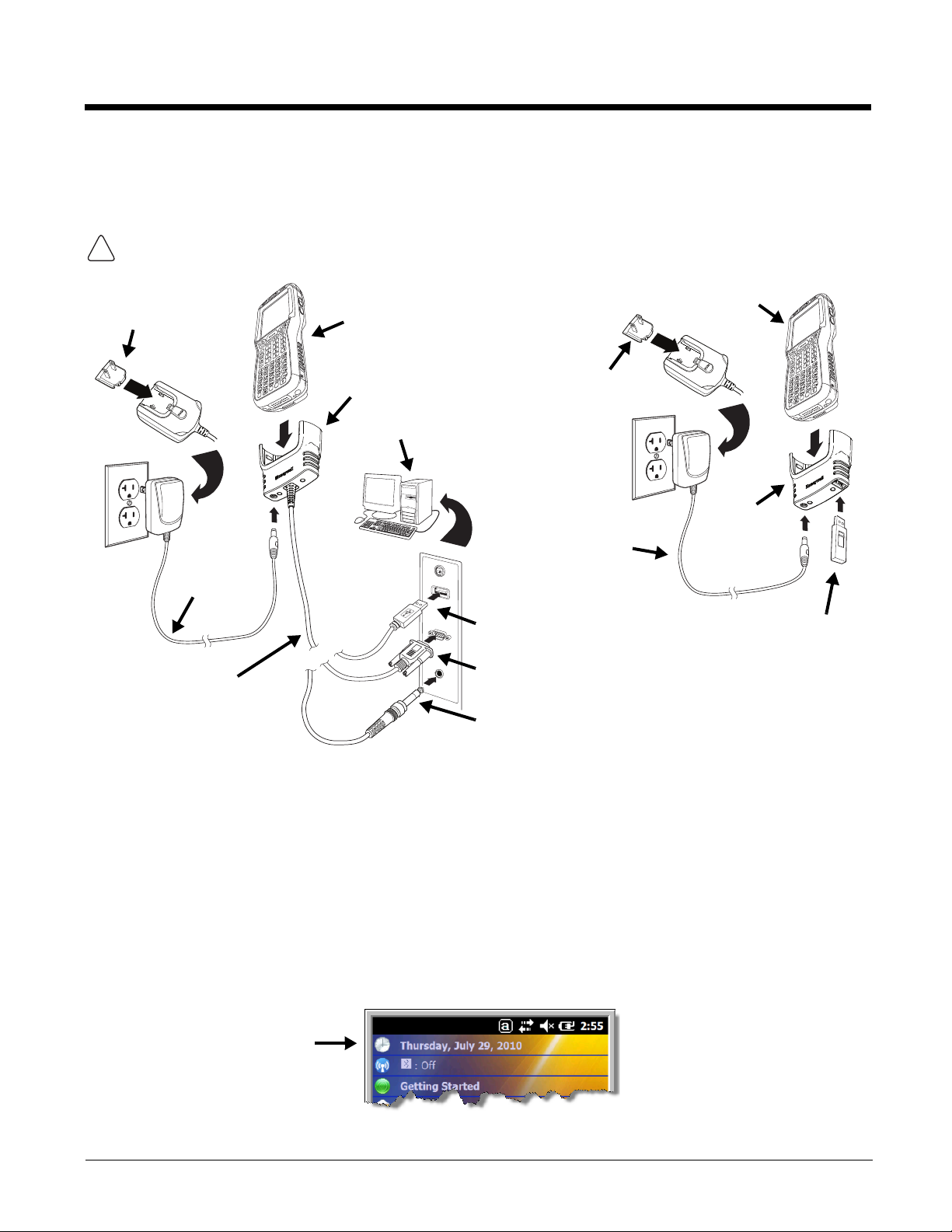
Using the Charging/Communication Cables
!
RS232 Connector
Host Device
Power
Cable
Or
USB Connector
COMM Cable
Plug
Adapter
Cable Cup
Or
RS232, DEX A/V Connector
Dolphin 99EX
(shown) or 99GX
Plug
Adapter
Power
Cable
Client Device
Charging
Cup
Dolphin 99EX (shown) or 99GX
Use only UL Listed power supply, which has been qualified by Honeywell with output rated at 5VDC and
3 amps with the device.
Ensure all components are dry prior to mating terminals/batteries with peripheral devices. Mating wet
components may cause damage not covered by the warranty.
Step 3. Boot the Terminal
The terminal begins booting as soon as power is applied. Do NOT press any keys or interrupt the boot
process. When the boot process is complete, the Home screen appears, and the terminal is ready for
use.
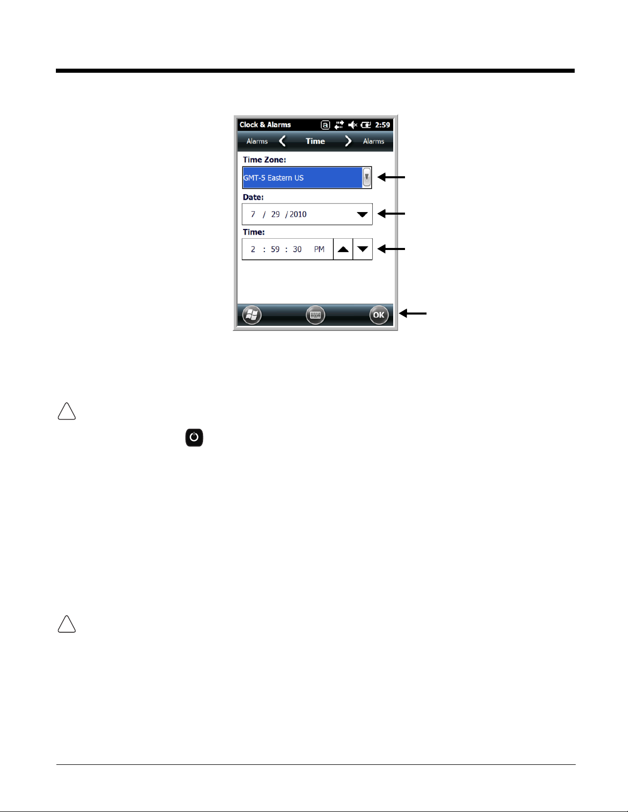
Step 4. Set the Time Zone, Time, and Date
On the Home screen, tap the line that displays the time and date. When the Clock & Alarms screen
appears, tap the arrow to the right of the time zone to open the drop down menu. Select the appropriate
time zone from the menu. Set the correct time and date in the remaining fields and tap OK to save.
1 - 3
Page 16
Replacing the Main Battery Pack
!
!
Note: Before replacing the main battery pack, read the Guidelines for Battery Pack Use and Disposal on page 2-14.
Ensure all components are dry prior to placing the battery in the terminal. Mating wet components may cause
damage not covered by the warranty.
1. Press the Power key to put the terminal in Suspend Mode (see page 1-12).
2. Release the hook securing the hand strap to the back panel of the terminal near the speaker (99EX
models only).
3. Remove the battery door by lifting up the latches near the base of the battery door.
4. Wait at least 3 seconds, and then remove the battery. This process allows the device to shut down
properly and maintains memory during the battery swap.
5. Insert the new battery into the battery well.
6. Replace the battery door. Apply pressure to engage the door latch. The battery door must be
installed prior to powering the unit.
7. Reattach the hand strap.
We recommend use of Honeywell Li-poly or Li-Ion battery packs. Use of any non-Honeywell battery may result
in damage not covered by the warranty.
1 - 4
Page 17
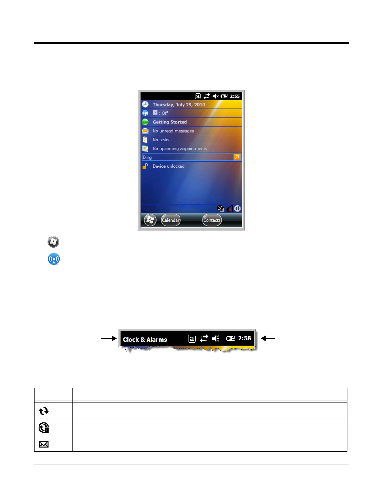
Home Screen
Text here indicates
the active program.
Icons here indicate the
status of various system
functions.
After the Dolphin terminal initializes the first time, you see the Home screen.
Tap to reach the Start screen from the home screen.
Tap to access the Dolphin Wireless Manager (see page 7-6) from the home screen.
Title Bar
The Title bar, located at the top of the screen, displays the active program, the status of various system
functions, and the current time. Tapping on the title bar provides access to the Horizontal Scroll. The
scroll provides access to additional programs and application screens. For additional information, see
Horizontal Scroll on page 1-8.
Icons in the Title Bar
Indicator Meaning
Synchronizing data
The terminal could not synchronize data with the workstation via ActiveSync.
New e-mail
1 - 5
Page 18

Icons in the Title Bar
Indicator Meaning
New text message
New voicemail
New instant message
Vibrate on
Ringer off
Speakerphone on
Voice call in progress
Calls are forwarded
Call on hold
Missed call
Data call in progress
A battery error has occurred. Replace the main battery pack with a Honeywell Li-poly or Li-ion
battery pack.
Battery is has a full charge
Battery has a high charge
Battery has a medium charge
Battery has a low charge
Battery has a very low charge and requires charging
Terminal is running on external power. If a battery pack is installed, the battery is charging in the
background.
The terminal is not connected to external power. A battery is installed, but is defective; specifically,
its charge level cannot be measured.
No SIM card is installed
Active network connection
1 - 6
Page 19

Icons in the Title Bar
Indicator Meaning
No active network connection
GPRS available
GPRS connecting
GPRS in use
HSDPA available
HSDPA connecting
HSDPA in use
EDGE available
EDGE connecting
EDGE in use
UMTS available
UMTS connecting
UMTS in use
Radio is off
The radio is not connected to a network.
The radio is connected. The bars indicate the signal strength.
No radio signal
The terminal is searching for a signal.
Wi-Fi is on, but device is not connected
Wi-Fi data call
Pending alarm
Bluetooth
1 - 7
Page 20
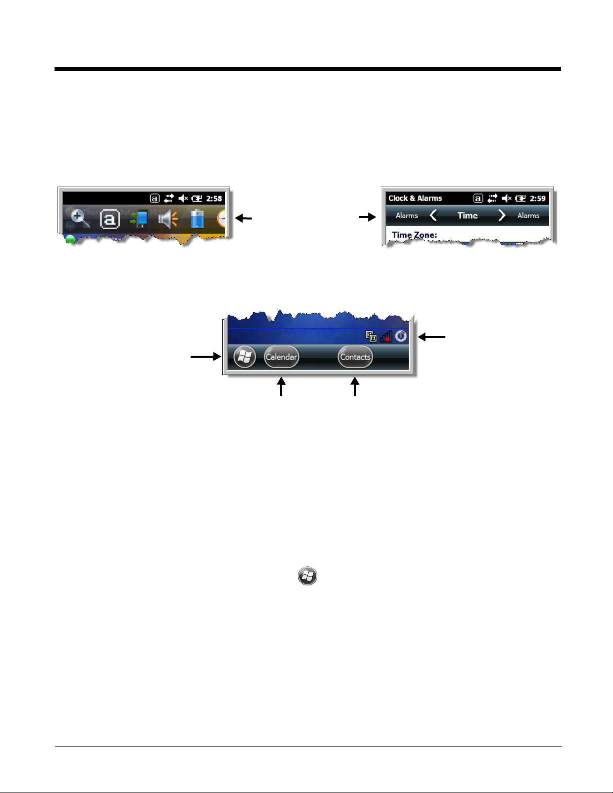
Horizontal Scroll
The content of the
Horizontal scroll
changes according to
the open application.
The icons change according to the open application.
The Task tray displays icons
for programs running in the
background.
The Tile bar displays icons you
use to open and close screens,
menus, and features.
The Horizontal Scroll, located at the top of most application windows, provides access to additional
application screens. You can flick left or right on the scroll or tap each label on the scroll, until you get to
the desired screen. Tapping a label to the left or right of the center item brings new labels into view.
Note: Tap the Title bar to access the horizontal scroll if it is not visible on the screen.
Tile Bar
The Tile bar is located at the bottom of application windows.
Pop-Up Menus
With pop-up menus, you can quickly choose an action for a selected item. To access a pop-up menu, tap
and hold the stylus on the item name of the action you want to perform. When the menu appears, lift the
stylus, and tap the action you want to perform.
Tap anywhere outside the menu to close the menu without performing an action.
Selecting Programs
To see the programs loaded on your terminal, tap to access the Start Menu. To open a
program, tap once on the program icon. To reposition an icon on the Start Menu, tap and hold the stylus
on the icon, then drag the icon to the desired position.
1 - 8
Page 21

File Explorer
You can also use the File Explorer to find files and organize these files into folders.
1. Tap > File Explorer .
2. Tap the Up button at the bottom of the screen to move up one level in the directory.
3. You can move files in File Explorer by tapping and holding on the item you want to move, then
tapping Cut or Copy on popup menu.
4. Navigate to the folder you want to move the file to, then tap and hold a blank area of the window.
5. Tap Paste on the pop-up menu.
Note: If there is no blank space available in the window, tap Menu on the command bar, navigate to the end of the
menu using the down arrow, then tap Edit > Paste.
1 - 9
Page 22

File Provisioning on the 99EX and 99GX
!
!
\IPSM\Honeywell
The IPSM folder is the only partition on the 99EX that persists across a kernel upgrade (*.UPG file extension). During a kernel upgrade, files are automatically copied from the \IPSM\Honeywell\Autoin-
stall folder and then installed in the \Honeywell (root file system) folder as part of the upgrade
process.
\IPSM\Honeywell\AutoInstall
The files in the IPSM\Honeywell\AutoInstall folder are only installed when a factory reset or ker-
nel upgrade occurs. Once the files are installed, they persist through hard and soft resets. If a file is
added to the folder and a hard or soft reset is performed, it will have no effect. If a program is manually
removed using the Remove Programs application (see page 6-17), then the program is not automatically
re-installed on a hard or soft reset.
\Honeywell
The Honeywell partition or root file system partition is persistent over a Hard Reset, Soft Reset, and the
removal of the battery pack or the removal of AC power. However, during a kernel upgrade the root file
system is reformatted so all data in the folder is deleted and replaced by any files in the \IPSM\Honey-
well\AutoInstall folder as part of the upgrade process.
To prevent data loss, back up all user data to an SD card or external memory device before performing an upgrade.
\Honeywell\AutoInstall
If you run a CAB file from within the \Honeywell\AutoInstall (user store) folder, after the program
has been installed, the CAB file will be deleted from the User Store. The program remains installed
through all successive Hard and Soft resets.
If you want the program to be part of the Autoinstall that occurs after a factory reset or software upgrade,
paste the program file(s) in both the \IPSM\Honeywell\Autoinstall folder and the
\Honeywell\Autoinstall.
Contact a Honeywell technical support representative for information on how to perform a factory reset.
For contact information, see Customer Support or go to www.honeywellaidc.com.
To prevent data loss, back up all user data to an SD card or external memory device before performing an upgrade.
Contact a Honeywell technical support representative for information on available software upgrades for
your Dolphin terminal, see Customer Support or go to www.honeywellaidc.com.
Search
The Search feature helps you quickly locate information. Tap > Search Phone .
Enter the text you want to find, select a data type, and then tap Go to start the search. Select Larger
than 64 KB in the Type drop-down field to quickly find information that is taking up storage space.
1 - 10
Page 23

Resetting the Terminal
ALT
CTRL
ENT
ALT
CTRL
ESC
!
ALT
CTRL
ESC
There are three types of system resets: a soft reset, a hard reset, or a factory reset. The soft and hard
resets preserve all data stored in the file system.
Soft Reset (Warm Boot)
A soft reset re-boots the device and preserves any objects created in RAM. You would perform a soft
reset when:
• the terminal fails to respond.
• after installing some software applications.
• after making changes to certain system settings, such as network cards.
1. Press and hold the CTRL + ENTER keys for approximately 5 seconds.
2. The decode and scan LEDs flash for approximately three seconds as the terminal resets.
3. When the reset is complete, the Home screen displays.
Hard Reset (Cold Boot)
A hard reset re-boots the device and closes any open applications running in RAM at the time of the
reset.
1. Press and hold the CTRL + ESC keys for approximately 5 seconds.
2. The decode and scan LEDs light for approximately 3 seconds.
3. The terminal re-initializes.
Factory Reset (Clean Boot)
If the terminal completely stops responding, you may need to perform a Factory Reset (Clean Boot).
Because resetting the terminal can result in data loss, use this method only if all other recovery methods
have failed. When a reset is performed, all personal content is erased (e.g., emails, pictures, contacts)
and all factory default settings are restored on the terminal. The reset discards any account information
you added.
Caution: A Factory Reset (Clean Boot) erases the memory in the terminal, including all
applications and data files, with the exception of those found in the Flash File Store
or any removable storage.
To perform a Factory Reset (Clean Boot):
1. Press and hold the CTRL + ESC keys simultaneously for approximately 5 seconds.
You may hear a clicking sound when you hold the keys down.
2. When the white Honeywell splash screen appears, enter code 1277 on the keyboard.
For terminals with a 34-Key Numeric (Calculator) Keyboard (see page 5-8), enter code 7811 instead
of 1277.
1 - 11
Page 24

3. Select Perform Factory Reset from the menu, and then press ENT .
ENT
SCAN
The following message appears on the terminal screen:
“All installed applications & customized settings will be deleted. Do you want to proceed?”
4. Press Y for yes, proceed with the Factory Reset.
If you change your mind and do not want to proceed, press N for no and the terminal will launch the
current image instead of a factory reset.
Suspend Mode
The terminal goes into Suspend Mode automatically when the terminal is inactive for a programmed
period of time. You can program this time on the Advance tab of the Power System Setting; see Power
on page 6-16.
To put the terminal into Suspend Mode manually, press the Power key and the screen turns off.
To wake the terminal from Suspend Mode, press the Power key or SCAN key .
Note: You should always put the terminal in suspend mode before removing the battery door. For information on
removing the battery, see Replacing the Main Battery Pack on page 1-4.
1 - 12
Page 25

2
Hardware Overview
Standard Configurations
99EX Models
WLAN & WPAN
• Microsoft Windows Embedded Handheld
6.5 Classic
• OMAP3715 (1Ghz)
• 512MB* RAM X 1GB Flash
• Four keyboard options
• 3.7V Li-poly standard battery pack or
optional extended 3.7V Li-ion rechargeable
battery pack
• Adaptus Imaging Technology: N5603ER/
SR/HD or N5600ER/SR/HD image engines
• 802.11a/b/g/n and Bluetooth
WLAN, WPAN, with GPS
• Microsoft Windows Embedded Handheld
6.5 Classic
• OMAP3715 (1Ghz)
• 512MB* RAM X 1GB Flash
• Four keyboard options
• 3.7V Li-poly standard battery pack or
extended 3.7V Li-ion rechargeable battery
pack
• Adaptus Imaging Technology: N5603ER/
SR/HD or N5600ER/SR/HD image engines
• 802.11a/b/g/n and Bluetooth
•GPS
WLAN, WPAN, & WWAN
WLAN, WPAN & Camera
• Microsoft Windows Embedded Handheld
6.5 Classic
• OMAP3715 (1Ghz)
• 512MB* RAM X 1GB Flash
• Four keyboard options
• 3.7V Li-poly standard battery pack or
extended 3.7V Li-ion rechargeable battery
pack
• Adaptus Imaging Technology: N5603ER/
SR/HD or N5600ER/SR/HD image engines
• 802.11a/b/g/n and Bluetooth
• 3.1 megapixel auto control color camera
•
WLAN, WPAN, with GPS & Camera
• Microsoft Windows Embedded Handheld
6.5 Classic
• OMAP3715 (1Ghz)
• 512MB* RAM X 1GB Flash
• Four keyboard options
• 3.7V Li-poly standard battery pack or
extended 3.7V Li-ion rechargeable battery
pack
• Adaptus Imaging Technology: N5603ER/
SR/HD or N5600ER/SR/HD image engines
• 802.11a/b/g/n and Bluetooth
•GPS
• 3.1 megapixel auto control color camera
•
WLAN, WPAN, & WWAN with GPS
• Microsoft Windows Embedded Handheld
6.5 Professional
• OMAP3715 (1Ghz)
• 512MB* RAM X 1GB Flash
• Four keyboard options
• Extended 3.7V Li-ion rechargeable battery
pack
• Adaptus Imaging Technology: N5603ER/
SR/HD or N5600ER/SR/HD image engines
• 802.11a/b/g/n, Bluetooth, and GSM/
HSPA+
• Microsoft Windows Embedded Handheld
6.5 Professional
• OMAP3715 (1Ghz)
• 512MB* RAM X 1GB Flash
• Four keyboard options
• Extended 3.7V Li-ion rechargeable battery
pack
• Adaptus Imaging Technology: N5603ER/
SR/HD or N5600ER/SR/HD image engines
• 802.11a/b/g/n, Bluetooth, and GSM/
HSPA+
•GPS
2 - 1
Page 26

WLAN, WPAN, WWAN with GPS & Camera
• Microsoft Windows Embedded Handheld
6.5 Classic
• OMAP3715 (1Ghz)
• 512MB* RAM X 1GB Flash
• Four keyboard options
• Extended 3.7V Li-ion rechargeable battery
pack
• Adaptus Imaging Technology: N5603ER/
SR/HD or N5600ER/SR/HD image engines
• 802.11a/b/g/n, Bluetooth, and GSM/
WLAN, WPAN, & WWAN
• Microsoft Windows Embedded Handheld
6.5 Classic
• OMAP3715 (1Ghz)
• 512MB* RAM X 1GB Flash
• Four keyboard options
• Extended 3.7V Li-ion rechargeable battery
pack
• Adaptus Imaging Technology: N5603ER/
SR/HD or N5600ER/SR/HD image engines
• 802.11a/b/g/n, Bluetooth, and GSM/CDMA
HSPA+
•GPS
• 3.1 megapixel auto control color camera
•
WLAN, WPAN, & WWAN with GPS
• Microsoft Windows Embedded Handheld
6.5 Classic
• OMAP3715 (1Ghz)
• 512MB* RAM X 1GB Flash
• Four keyboard options
• Extended 3.7V Li-ion rechargeable battery
pack
• Adaptus Imaging Technology: N5603ER/
SR/HD or N5600ER/SR/HD image engines
• 802.11a/b/g/n, Bluetooth, and GSM/CDMA
•GPS
WLAN, WPAN, WWAN with GPS & Camera
• Microsoft Windows Embedded Handheld
6.5 Classic
• OMAP3715 (1Ghz)
• 512MB* RAM X 1GB Flash
• Four keyboard options
• Extended 3.7V Li-ion rechargeable battery
pack
• Adaptus Imaging Technology: N5603ER/
SR/HD or N5600ER/SR/HD image engines
• 802.11a/b/g/n, Bluetooth, and GSM/
HSPA+ or GSM/CDMA
•GPS
• 3.1 megapixel auto control color camera
•
Some configurations of the 99EX are available with an external housing made of plastic that is specifically designed for the healthcare industry. For more information, see Healthcare Housing on page 2-12.
99GX Models*
WLAN & WPAN
• Microsoft Windows Embedded Handheld
6.5 Classic
• OMAP3715 (1Ghz)
• 512MB** RAM X 1GB Flash
• Four keyboard options
• 3.7V Li-poly standard or extended 3.7V Liion rechargeable battery pack
• Adaptus Imaging Technology: N5603ERor
N5603SR image engine
• 802.11a/b/g/n and Bluetooth
* Standard 99GX configurations based on current offerings.
** RAM specifications are based on current offerings. Older Dolphin models may have 256MB of RAM.
Ta p Settings > System > About > Version to view how much memory is available on the terminal.
2 - 2
Page 27

Peripherals for the 99EX and 99GX
Each of the following items is sold separately to enhance the capabilities of your Dolphin terminal.
Dolphin 99GX terminals are compatible with 99EX peripherals.
Dolphin HomeBase Device
The Dolphin HomeBase device is a charging and communication cradle supporting both RS232 and
USB communications, which enables the terminal to interface with the majority of PC-based enterprise
systems. The USB host port is Hi-Speed 2.0v compliant. This device also contains an auxiliary battery
well that charges a spare Honeywell Li-poly or extended Li-ion battery.
For more information, see Dolphin 99EX HomeBase Device (Model 99EX-HB) on page 11-1.
Dolphin Mobile Base Device
The Dolphin Mobile Base device is a charging and communication cradle designed specifically for inpremise and in-transit data collection applications. It features a flexible mounting bracket and a cigarette
lighter adapter to adapt it to your environment.
The serial connector supports RS232 communication and power out to peripheral devices, such as
handheld scanners. The USB port is client Hi-Speed 2.0v compliant. You can connect the base to a
peripheral device, such as a memory stick or to a printer using a standard USB cable.
For more information, see Dolphin 99EX Mobile Base Device (Model 99EX-MB) on page 13-1.
Dolphin eBase Device
The Dolphin Ethernet (eBase) device enables a single 99EX mobile computer to communicate with a
host device over an Ethernet network. In addition, the ebase is equipped with a USB host port that is HiSpeed 2.0v compliant, which enables the terminal to interface with the majority of PC-based enterprise
systems. This device also contains an auxiliary battery well that charges a spare Honeywell Li-poly or
extended Li-ion battery.
For more information, see Dolphin 99EX eBase Device (Model 99EX-EHB) on page 12-1.
Dolphin Net Base Device
The Dolphin Net Base device enables up to four 99EX mobile computers to communicate with a host
device over an Ethernet network. In addition, the Net Base provides a second RJ45 Ethernet port for
connection to an additional device such as a printer, workstation, eBase, or another Net Base.
For more information, see Dolphin 99EX Net Base Device (Model 99EX-NB) on page 15-1.
Dolphin ChargeBase
The Dolphin ChargeBase is a 4-slot charging cradle that holds, powers, and charges terminals.
For more information, see Dolphin 99EX ChargeBase Device (Model 99EX-CB) on page 14-1.
Dolphin QuadCharger Device
The Dolphin QuadCharger device is a 4-slot charging station for 99EX standard Li-poly or extended Liion battery packs.
For more information, see Dolphin 99EX QuadCharger Device (Model 99EX-QC) on page 16-1.
2 - 3
Page 28

Accessories for the 99EX and 99GX
Stylus for Dolphin 99EX with WWAN
and 99GX Models
Stylus for Dolphin 99EX with WLAN
Each of the following items is sold separately to enhance the capabilities of your Dolphin terminal.
Note: When using accessories where the terminal is worn on the body, the terminal’s touch panel must face away
from the body.
Dolphin Mobile Charger
The Dolphin Mobile Charger is a charging cable that connects the terminal directly to a 12 Volt DC power
source, such as a cigarette lighter port inside a vehicle, eliminating the need for a cradle. Intelligent battery technology on-board the terminal ensures proper charging. The Dolphin 99EX Mobile Charger is an
ideal low-cost charging solution for in-transit mobile applications.
Communication/Charging Cables
Dolphin communication/charging cable kits are an all-in-one solution for mobile applications. Each cable
kit powers the terminal, charges its main battery, and communicates with host or peripheral devices without the need for a cradle. Cable kits can support RS232, USB client, and USB host communications.
U.K. or European power cords are available.
Storage Holster
Holsters provide convenient storage for terminals in mobile environments. The holsters feature a front
pocket that holds an extra battery, a side loop to hold an extra stylus, and a belt loop to secure the holster
to a belt. The standard holster includes two additional stylus loops on the front of the holster.
Protective Enclosure
Protective enclosures help seal and protect terminals from damage while providing full access to all terminal parts and features. These enclosures feature a swivel clip on the back that enables you to secure
the enclosure to a belt. Enclosures also come with an adjustable shoulder strap for added convenience.
Stylus Kits
Each Dolphin is shipped with a stylus and a stylus tether used to secure the stylus to the terminal to prevent loss. Kits containing three styli and three tethers are available for purchase. When ordering specify
your Dolphin model number to ensure the correct stylus selection.
Battery Pack
The rechargeable battery pack provides the main power for the terminal. For more information, see
Batteries on page 2-13.
2 - 4
Page 29
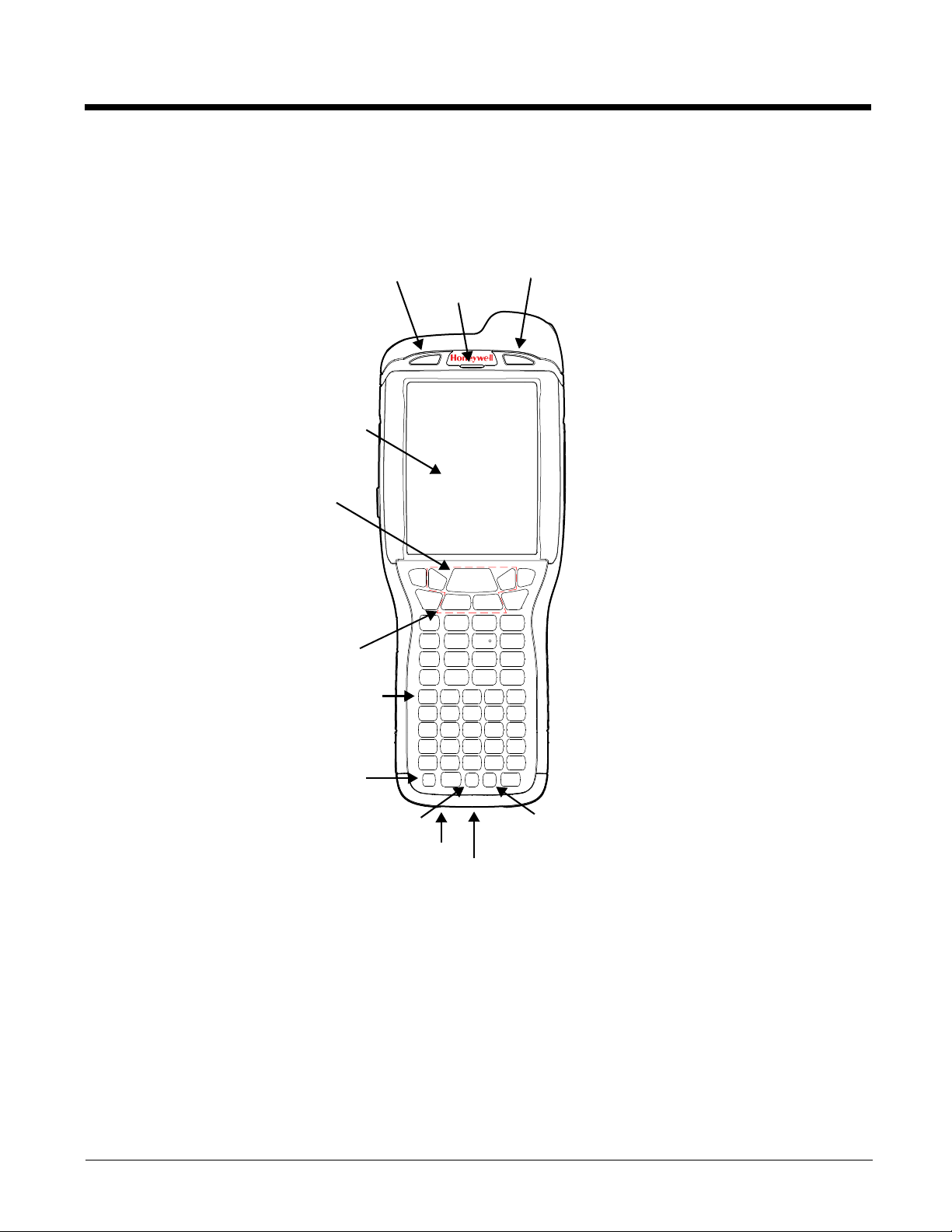
Front Panel: 99EX and 99GX
Power Key
Touch Panel Display
Navigation Keys
SCAN Key
Recessed Keyboard
Front Speaker
I/O Connector
General Notification LED
Red Modifier KeyBlue Modifier Key
Microphone
Charge Indicator LED
Note: Your Dolphin model may differ from the model illustrated; however, the features noted are standard for all
99EX and 99GX models unless otherwise indicated.
Note: The illustration above shows the 55-Key Full Alpha/Numeric Keyboard option. For a complete overview of the
For a description of each callout, see Front Panel Features for the 99EX and 99GX (see page 2-6).
optional keyboards available for the 99EX/99GX, see Using the Keyboards on page 5-1.
2 - 5
Page 30

Front Panel Features for the 99EX and 99GX
Blue Modifier Key
See Using the Modifier Keys on page 5-3.
Front Speaker
The front speaker is the receiver for handset phone (voice) calls and/or VoIP calls depending
on the Dolphin model.
General Notification LED
The light emitting diode (LED) located above the top right corner of the LCD display flashes
and illuminates during resets, scanning/imaging, and taking a picture. This LED can be
programmed by various software applications.
Charge Indicator LED
The light emitting diode (LED) located above the top left corner of the LCD display illuminates
when the Power Tools BattMon application is enabled and the device is on AC charge. For
more information, consult the Dolphin Power Tools User’s Guide for Windows Embedded
Handheld 6.5.
Microphone
The integrated microphone provides audio input for handset and speaker phone voice calls
and/or VoIP calls depending on the Dolphin model.
Navigation Keys
The centrally located navigation keys enable you to move and position the cursor through
software programs. The up and down arrows are programmed to perform specific functions
when pressed in combination with the Blue and Red modifier keys. For more details, see Using
the Navigation Keys on page 5-3.
Power Key
The power key located at the lower left corner of the keypad puts the terminal in Suspend
Mode or wakes the terminal from Suspend Mode. See Suspend Mode on page 1-12.
Recessed Keyboard
There are three keyboard options: a 34-key alpha/numeric keyboard, a 43-key alpha/numeric
keyboard or a 55-key full alpha/numeric keyboard. For a complete overview of each keyboard,
see Using the Keyboards on page 5-1.
Red Modifier Key
See Using the Modifier Keys on page 5-3.
SCAN Key
The SCAN key is centrally located for easy access with the right or left hand. When pressed,
the SCAN key activates the scanner/imager. The SCAN key also functions as a system wakeup control for the terminal.
2 - 6
Page 31

Touch Panel Display
Image/Scan Engine Window
Rear
Speaker
Battery Door
Fastener for the
Stylus Tether
Flashlight/
Camera Flash
(99EX Only)
Color Camera
(99EX Only)
Hand Strap
(99EX Only)
Stylus Slot
Battery Door Release
Hand Strap Hook
(99EX Only)
Image/Scan Engine Window
Rear Speaker
Battery Door
Fastener for the
Stylus Tether
Battery Door Release
Scan Trigger
(99GX Only)
Handle
(99GX Only)
The color 3.7 inch liquid crystal display (LCD) touch panel is covered with an industrial,
protective lens for greater durability. The video graphic array (VGA) display resolution is
480 X 640.
The color LCD (16 bit RGB) uses thin film transistor (TFT) technology. The touch panel
backlight illuminates when the screen is touched, but not when the Backlight key is pressed.
For more information, see Backlight on page 6-9.
The touch panel can be activated by the stylus (included with the terminal) or a finger. For more
information, see Using the Touch Panel on page 2-12.
Back Panel: 99EX and 99GX
Note: Your Dolphin model may differ from the models illustrated; however, the features noted are standard for all
99EX and 99GX models unless otherwise indicated.
For a description of each callout, see Back Panel Features for the 99EX and 99GX below.
2 - 7
Page 32

Back Panel Features for the 99EX and 99GX
Battery Door
The battery door secures the Li-ion or Li-poly battery pack in the terminal’s battery well. For
information on how to remove the battery, see Replacing the Main Battery Pack on page 1-4.
Color Camera (99EX Only)
The 3.1-Megapixels Resolution color camera provides easy picture capture with Automated
Camera Control (ACC). Additional features include automated picture profiles and an
Application Programming Interface (API).
Fastener for the Stylus Tether
The Stylus Tether helps prevent accidental loss when the stylus is not stored in the stylus slot.
A stylus tether is a coiled, elastic cord that tethers the stylus to the terminal. Secure one end
of the cord to the back panel of the terminal and the other end to the stylus.
Flashlight/Camera Flash (99EX Only)
The flashlight/camera flash is located on the back panel of the terminal. When used as a
Flashlight, press the Blue key + key to turn the flashlight on or off. When used as a
Camera Flash with the terminal’s color camera, the flash is controlled by the camera
application.
Hand Strap (99EX Only)
The 99EX comes with a removable, elastic hand strap.
Image/Scan Engine Window
The available image engines read and decode linear, stacked linear (e.g., PDF417), and 2D
matrix bar code symbologies. The available image engines contain a laser aimer for greater
accuracy. The laser apertures for the imaging engines’ laser aimers are contained behind this
window. For more details, see Using the Scan Image Engine on page 3-1.
Memory Card Socket and SIM Card Socket
The memory card socket provides the user with the option to expand the terminal memory
capacity using microSD™ or microSDHC™ memory interfaces.
Note: Honeywell recommends the use of Single Level Cell (SLC) industrial grade microSD or
microSDHC memory cards with Dolphin terminals for maximum performance and durability.
Contact a Honeywell sales representative for additional information on qualified memory card
options.
The Subscriber Identity Module (SIM) card socket provides the option to install an active
service provider SIM card for cellular network connections on WWAN equipped models. A
standard size SIM card fits the socket.
Both sockets are located under a protective door in the battery well of the terminal. A T6 Torx
screw secures the socket door closed. The environmental rating of the terminal is preserved
when the socket door, battery pack, and the battery door are properly installed sealing the
cards against moisture and particle intrusion.
For information on card installation, see Installing a Memory Card on page 2-17 or Installing a
SIM Card on page 8-2.
2 - 8
Page 33
Rear Speaker
Left Button
IrDA Port
Extended Li-ion Battery Door
Standard Li-poly Battery Door
The integrated rear speaker sounds audio signals as you scan bar code labels and enter data.
The integrated speaker also supports playback of wave and MP3 files, software mixer, and
speakerphone for WWAN/GSM audio. The operating frequency range is 600-3000Hz at
>90dB.
Scan Trigger (99GX Only)
The back panel of the 99GX contains an integrated, handle for a more ergonomic grip in scan
intensive applications. Press the scan trigger to activate the imager/scanner.
Stylus Slot
The stylus is used to operate the touch panel. The back panel of the terminal features a storage
slot to hold the stylus when not in use. The stylus features a special tip for added accuracy and
ease of use.
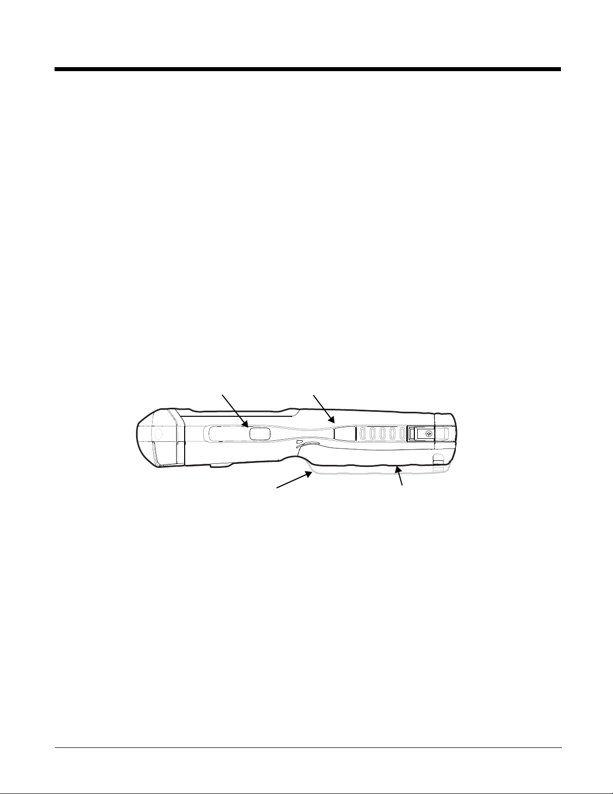
Side Panels: 99EX and 99GX
The left and the right side panels of the Dolphin contain different features.
Note: Your Dolphin model may differ from the models illustrated; however, the features noted are standard for all
99EX and 99GX models unless otherwise indicated.
Left Side
Left Button
IrDA Port
By default, the Left Button triggers the scanner/imager. You can reassign the button to launch
applications or execute commands. For additional information, see Changing Button
Assignments on page 6-4.
The IrDA port enables infrared communication. The maximum data transfer speed is 115 kbps.
For more information about using this port, see Using the IrDA Port on page 7-2.
Note: The infrared LED aperture is located behind the IrDA Port window.
2 - 9
Page 34

Right Side
Right Button
Volume Control Button
Lower Volume | Raise Volume
Extended Li-ion Battery Door
Standard Li-poly Battery Door
Lanyard Strap (99GX Only)
Scan Trigger (99GX Only)
Rear Speaker
Handle (99GX Only)
•
Handle (99GX Only)
The handle is integrated into the back panel of the terminal and is ergonomically designed to
be comfortable through repetitive scans.
Right Button
By default, the Right Button triggers the scanner/imager. You can reassign the button to launch
applications or execute commands. For additional information, see Changing Button
Assignments on page 6-4.
Scan Trigger (99GX Only)
Press the scan trigger to activate the imager/scanner.
Volume Control Button
Press the top or bottom of the volume button to raise or lower the volume of the active speaker.
2 - 10
Page 35

Lanyard Strap (99GX Only)
2468 10 12 14 16 18
1 3 579 11 13 15 17
The 99GX comes with a removable lanyard strap that attaches to the bottom of the handle.
Bottom Panel: 99EX and 99GX
Pin Description
1GND
2GND
3 USBC_DET
4 USBC_D-
5RTS
6 USBC_D+
7DTR
8SPK
9 Audio_GND
10 MIC
11 CTS
12 USBH_D-
13 5V_OUT
14 USBH_D+
15 TXD
16 RXD
17 VCC
18 VCC
Note: Signals referenced are for a DTE device.
I/O Connector
The I/O connector powers the terminal, charges the main battery, and facilitates communication. All Dolphin peripherals are designed to work exclusively with this connector.
The I/O connector supports RS232 and high speed USB v2.0 communication. For RS232, the maximum
communication speed is 115.2 Kbps with seven baud rate settings. For USB, the communication speed
is up to 480 Mbps.
I/O Power Out
The I/O connector also provides power out (to peripheral devices) +5V at 500mA. This means that,
with the proper cable, the terminal can power another device. By default, power out is disabled, but the
5V output may be enabled, see Five Volt Control on page 6-12.
2 - 11
Page 36

Using the Touch Panel
Honeywell defines proper use of the terminal touch panel as using a screen protector and proper stylus.
Screen protectors maintain the ongoing integrity (i.e., prevent scratching) of the touch panel, which is
why their use is recommended for applications that require a high to medium level of interface with the
touch panel, such as signature capture for proof of delivery.
Honeywell advocates the use of screen protectors on all Dolphin devices. We recommend implementing
a screen protector replacement program to ensure that screen protectors are replaced periodically when
signs of damage/wear are noticeable. Replacement screen protectors can be purchased directly from
Honeywell. Please contact a Honeywell sales associate for details.
Honeywell also mandates use of a proper stylus, which is one that has a stylus tip radius of no less than
0.8 mm. Use of the Honeywell stylus included with the terminal is recommended at all times.
Honeywell warranty policy covers wear on the touch panel for the first twelve (12) months if a screen protector is applied and an approved stylus is used for the 12 month duration covered by the warranty.
Installing a Screen Protector
Dolphin terminals ship with a screen protector already installed. You will need to replace the screen protector at regular intervals.
1. After the current screen protector has been removed from the touch panel, clean the touch panel
thoroughly with a clean, non-abrasive, lint-free cloth. Make sure there is no debris on the touch
panel.
2. Align the exposed section of the protector with the bottom edge of the touch panel. Make sure that
the screen protector is flush with each side of the touch panel. To reposition, lift up gently and
reapply.
3. Press the screen protector firmly and carefully across the surface of the touch panel as you peel
away the backing.
4. If necessary, smooth out any air pockets or bumps.
Healthcare Housing
Some configurations of the 99EX terminal are available with an external plastic housing that is designed
to resist the effects of harsh chemicals in a healthcare environment. The plastic is crystalline in nature,
which helps prevent chemicals from seeping through the housing.
Important! The following cleaning solutions have been tested to assure safe cleaning of your terminal’s
disinfectant-ready housing. They are the only solutions approved for use with these
terminals. Damage caused by the use of cleaners other than those listed below may not be
covered by the warranty.
®
256
®
HB wipes
®
Plus wipes
®
Bleach wipes
®
wipes
• Sani-Cloth
• Sani-Cloth
• Sani-Cloth
• Super Sani-Cloth
• Isopropyl Alcohol wipes (70%)
• CaviWipes™
•Virex
2 - 12
Page 37

•409® Glass and Surface Cleaner
!
!
®
•Clorox
• Windex
• Gentle dish soap and water
•
Note: The use of cleaning solutions containing bleach may cause the overmold on the housing to discolor.
Bleach (10%)
®
Blue
Batteries
There are three types of battery power: the main battery pack installed in the back panel, the backup
battery located inside the terminal and the Real Time Clock (RTC) battery located inside the terminal.
They are designed to work together to prevent data loss when the terminal is in use over long periods.
All batteries must be completely charged before using a Dolphin terminal for the first time!
Note: The RTC battery will preserve the Real Time Clock 60 days after the main battery and internal backup battery
are fully depleted.
Main Battery Pack
We recommend use of Honeywell Li-ion or Li-poly battery packs. Use of any non-Honeywell battery may result
in damage not covered by the warranty.
•
Dolphin 99EX and 99GX model terminals are designed for use with standard battery pack model
99EX-BTSC (Li-poly 3.7V, 11.3 watt hour) and extended battery pack model 99EX-BTEC (Li-ion 3.7V,
18.5 watt hour) manufactured for Honeywell International Inc. The standard or extended battery pack is
the primary power source for the terminal. The Li-poly and Li-ion battery packs are designed to operate
in a temperature range of -10° to 50°C (14° to 122°F).
CAUTION - Read the Guidelines for Battery Pack Use and Disposal on page 2-14 and all cautionary
markings on the battery, charging peripheral, or device using the battery before attempting to install, use, or
charge the battery. Risk of fire and burns if improperly handled. Do not open, crush, heat above 60°C
(140
°F), or incinerate.
When the main battery pack is installed in the terminal, use one of the following peripherals:
• Dolphin 99EX HomeBase Device (Model 99EX-HB) (see page 11-1)
• Dolphin 99EX eBase Device (Model 99EX-EHB) (see page 12-1)
• Dolphin 99EX Mobile Base Device (Model 99EX-MB) (see page 13-1)
• Dolphin 99EX ChargeBase Device (Model 99EX-CB) (see page 14-1)
• Dolphin 99EX Net Base Device (Model 99EX-NB) (see page 15-1)
When the main battery pack is not installed in the terminal:
• Place the battery pack in the Dolphin 99EX QuadCharger Device (Model 99EX-QC) (see page 16-1)
• Place the battery pack in the Auxiliary Battery Well of the Dolphin 99EX HomeBase Device (Model
99EX-HB) (see page 11-2) or Dolphin 99EX eBase Device (Model 99EX-EHB) (see page 12-1).
For information on how to remove the main battery pack from the terminal, see Replacing the Main
Battery Pack on page 1-4.
Charging Time
The standard 3.7V Li-poly battery pack requires 4 hours to charge completely before initial use. The
extended 3.7V Li-ion battery pack requires 6 hours to charge completely before initial use.
Honeywell recommends charging the Dolphin terminal for at least 24 hours prior to initial use to ensure
the internal backup battery is fully charged.
2 - 13
Page 38

Battery Error Notification
If your terminal displays the following indicators, replace the main battery pack with a Honeywell Li-poly
or Li-ion battery pack. For information on how to remove the main battery pack from the terminal, see
Replacing the Main Battery Pack on page 1-4.
• appears in the Title bar at the top of the touch screen.
• The General Notification LED flashes red.
• A Notification appears on the Tile bar at the bottom of the touch screen.
Storing Batteries
To maintain top performance from batteries, avoid storing batteries outside of the following temperature
ranges:
• 14°F to 113°F (-10°C to +45°C) for short term storage of less than one month
• 32°F to 86°F (-0°C to +30°C) for long term storage
Do not store batteries in extremely high humidity. For prolonged storage, do not keep batteries stored in
a charger that is connected to a power source.
Guidelines for Battery Pack Use and Disposal
The following are general guidelines for the safe use and disposal of batteries:
• Do not disassemble or open crush, bend or deform, puncture or shred.
• Do not modify or remanufacture, attempt to insert foreign objects into the battery, immerse or expose
to water or other liquids, expose to fire, explosion or other hazard.
• Improper battery use may result in a fire, explosion or other hazard.
• We recommend use of Honeywell Li-ion or Li-poly battery packs. Use of any non-Honeywell battery
may pose a personal hazard to the user.
• Only use the battery for the system for which it is specified. Do not use a battery in any other manner
outside its intended use in Dolphin terminals and peripherals.
• Only use the battery with a charging system that has been qualified with the system per standard IEEE-
Std-1725-2006. Use of an unqualified battery or charger may present a risk of fire, explosion, leakage,
or other hazard.
• Replace the battery only with another battery that has been qualified with the system per this standard,
IEEE-Std-1725-2006. Use of an unqualified battery may present a risk of fire, explosion, leakage or
other hazard.
• Replace defective batteries immediately; using a defective battery could damage the Dolphin terminal.
• Never throw a used battery in the trash. Promptly dispose of used batteries in accordance with local
regulations.
• Do not short-circuit a battery or throw it into a fire; it can explode and cause severe personal injury. Do
not allow metallic conductive objects to contact battery terminals.
• If you observe that the Honeywell battery supplied is physically damaged, please send it to Honeywell
International Inc. or an authorized service center for inspection, see Customer Support on page xi.
• Avoid dropping the terminal or battery. If the terminal or battery is dropped, especially on a hard
surface, and the user suspects damage, send it to a Honeywell International Inc. or an authorized
service center for inspection, see Customer Support on page xi.
• If you are not sure the battery or charger is working properly, send it to Honeywell International Inc. or
an authorized service center for inspection.
• Excessive discharge can degrade battery performance. Recharge the battery when your terminal
indicates low battery power.
• Although your battery can be recharged many times, the battery life is limited. Replace it after the
battery is unable to hold an adequate charge.
2 - 14
Page 39

Internal Backup Battery
Located inside the terminal is a 3.6 Volt nickel metal hydride (NiMH) backup battery. The backup battery
prevents the terminal from being reset if you need to replace the main battery pack. It retains RAM data
during the battery pack exchange. A fully charged backup battery provides 30 minutes of backup time.
Note: When removing a battery from the terminal, put the device in Suspend Mode (see page 1-12) before removing
the battery door. Once the battery door is removed, wait at least 3 seconds before removing the main battery.
This process allows the device to shut down properly and maintains memory during the battery swap.
If at any time the backup battery becomes fully discharged of power (e.g., the terminal is left without the
main battery pack for more than 30 minutes), the terminal resets when power is supplied. All files are
retained, but you may need to restart any running applications. In addition, a fully discharged backup
battery requires a minimum of 24 hours of charging time to reach a full charge.
Note: Data and programs stored in Flash memory are not lost even if the internal backup battery fails.
Charging
The internal backup battery and the RTC battery are powered by the main battery pack. Therefore,
charging the internal batteries requires a charged main battery pack be installed in the terminal and the
terminal be connected to a charging device.
The internal backup battery must be fully charged before using the terminal for the first time. Honeywell
recommends charging the Dolphin terminal for at least 24 hours prior to initial use to ensure the internal
backup battery is fully charged. After that, if the internal backup battery becomes fully discharged of
power, it requires a minimum of 24 hours of charging time to function normally.
Guidelines for Use
Follow these guidelines to maximize the life of the internal backup battery:
• Keep a charged Li-ion or Li-poly battery pack in the terminal; the backup battery prematurely
discharges if there is not at least a partially charged battery in the terminal.
• Keep the terminal connected to power when the terminal is not in use.
Managing Battery Power
Letting the backup battery become fully discharged causes the terminal to lose all data in RAM. Honeywell recommends, you keep a charged battery pack in the terminal at all times to help prevent data loss.
The internal battery discharges prematurely if there is not at least a partially charged battery in the terminal. When you remove a battery pack, insert another charged battery pack in the terminal immediately.
Default Critical and Low Battery Points
When the terminal is running on battery power (as opposed to external power), warnings are displayed
when the battery reaches critical and low battery points. The warning points are determined by the following registry entry:
[HKEY_LOCAL_MACHINE\ControlPanel\Power]
There are two DWORD values in this registry entry: MedState and LowState.
The default values for these entries are as follows:
2 - 15
Page 40

MedState=25%
This sets the Low Battery point to 25%. When the battery hits the percentage charge specified
here, the user is notified.
LowState=10%
This sets the Critical Battery point to 10%. When the battery hits the percentage charge
specified here, the user is notified.
Note: Warnings do not appear when the terminal is on external power.
Setting Critical and Low Battery Points
Developers can reset the battery parameters in the registry from 0 (no warning) to 99 (would nearly
always warn). You can review and set these battery points in the RegEdit Power Tool.
1. Tap > Power Tools > RegEdit.
2. Drill down to HKEY_LOCAL_MACHINE > ControlPanel > Power.
3. Tap the Value Name to change the Value Data.
You can reset the Value Data from 0 (no warning) to 99 (would nearly always warn).
4. Tap OK to save changes.
For more information about the RegEdit Power Tool, refer to the Dolphin Power Tools User’s Guide available for download at www.honeywellaidc.com.
Checking Battery Power
1. Tap > Settings > System
2. Tap Power to view the power status of the main battery and the backup battery or tap Battery to
view detailed information on the installed battery pack.
Note: The Backup Battery gauge registers either 0% or 100%. The percentage is not an indication of the level
of charge remaining on the backup battery. An installed and functional battery registers 100%. A total
discharge or a battery error registers 0%.
For additional information on Advanced Power Settings, see page 6-16.
For additional information on the Battery Log Configuration, see page 6-10.
Hardware Maintenance
When needed, clean the image engine window and the LCD display with a clean, non-abrasive, lint-free
cloth. The terminal can be cleaned with a damp cloth. For additional information on hardware maintenance specific to the Dolphin Healthcare Housings, see page 2-12.
2 - 16
Page 41

Installing a Memory Card
Step 5
Step 7
Step 8
Step 9
Step 6
Step 10
Honeywell recommends the use of Single Level Cell (SLC) industrial
grade microSD or microSDHC memory cards with Dolphin terminals for
maximum performance and durability. Contact a Honeywell sales representative for additional information on qualified memory card options.
Note: Format all microSD/SDHC cards before initial use.
To install a memory card:
1. Press the Power key to put the terminal in Suspend Mode.
2. Release the hand strap hook near the speaker on the back panel of
the terminal.
3. Remove the battery door.
4. Wait at least 3 seconds, and then remove the battery.
®
5. Remove the T6 TORX
6. Lift up the lower left corner of the door to access the memory
socket.
7. Unlock the access door to the memory socket by sliding the door
toward the IrDA port side of the terminal.
screw securing the protective door closed.
8. Lift the door up to expose the socket.
9. Slide the microSD or microSDHC card into the door of the socket.
Note: Make sure the interface on the memory card is connected to the interface
in the socket; align the notch on the card with the notch of the socket.
10. Close and lock the access door.
11. Close the protective door over the memory socket. Install and
tighten the T6 TORX screw to secure the door closed.
12. Install the battery and the battery door. Reattach the hand strap to
the terminal.
13. Press the Power key or SCAN key to wake the terminal.
Installing a SIM Card
See Installing a SIM Card on page 8-2.
2 - 17
Page 42

2 - 18
Page 43

3
Using the Scan Image Engine
Overview
The Dolphin terminal houses a compact image engine that instantly reads popular 1D and 2D bar codes
and supports omni-directional aiming and decoding for greater flexibility in real-world settings. The
image engine can also capture black and white digital images, such as signatures and pictures of damaged inventory.
With the latest CMOS-based technology, the engine works like a digital camera and enables black and
white digital image capture, signature capture, and reading of OCR characters.
Angled Imaging
All imagers are installed at a 25 degree downward-facing angle for enhanced comfort and maneuverability while scanning.
N5603 Beam Divergence Angle
Engines Horizontal Beam Divergence Angle
(degrees)
N5603SR/HD
N5603ER
18.1 14.3
13.1 9.9
Vertical Beam Divergence Angle
(degrees)
Image Engine Specifications
Engines 1D 2D Image Capture Aiming Pattern Omni-Directional Aiming
N5603SR/ER/HD
N5600SR/ER/HD
YYY N5603 Red High-Vis
Aiming Pattern (page 3-5)
YYY N5600 Green Aiming
Beam (page 3-5)
Y
Y
3 - 1
Page 44

Depth of Field
The depth of field measurements used the following parameters:
• Distances are measured from the front of the engine.
• +23°C (+73°F), 0 lux
• Photographic quality codes
Focus N5603/N5600
High Density (HD)
Symbology Distance (in/cm) Delta
Near Far Near Far Near Far
3 mil
C39/128
5 mil
C39/128
7.5 mil
C39/128
10 mil
C39/128
15 mil
C39/128
20 mil
C39/128
100% UPC 1.9
5 mil
PDF417
2.0
(5.1)
1.4
(3.6)
1.4
(3.6)
1.4
(3.6)
1.3
(3.3)
2.3
(5.8)
(4.8)
1.4
(3.6)
3.4
(8.6)
4.8
(12.2)
5.6
(14.2)
5.5
(14.0)
7.8
(19.8)
9.2
(23.4)
7.1
(18)
4.8
(12.2)
(in/cm)
1.4
(3.6)
3.4
(8.6)
4.2
(10.7)
4.1
(10.4)
6.5
(16.5)
6.9
(17.5)
5.2
(13.2)
3.4
(8.6)
N5603/N5600
Standard Range (SR)
Distance (in/cm) Delta
-- -- - -
2.7
(6.9)
2.5
(6.4)
1.6
(4.1)
1.8
(4.6)
2.2
(5.6)
1.8
(4.6)
2.6
(6.6)
6.3
(16.0)
9.2
(23.4)
13.2
(33.5)
19.0
(48.3)
20.1
(51.1)
16.5
(41.9)
5.2
(13.2)
(in/cm)
3.6
(9.1)
6.7
(17)
11.6
(29.5)
17.2
(43.7)
17.9
(45.5)
14.7
(37.3)
2.6
(6.6)
N5603/N5600
Extended Range (ER)
Distance (in/cm) Delta
5.4
(13.7)
4.2
(10.7)
3.1
(7.9)
2.4
(6.1)
2.9
(7.4)
2.7
(6.9)
6.1
(15.5)
9.0
(22.9)
12.6
(32.0)
17.2
(43.7)
20.9
(53.1)
24.0
(61.0)
19
(43.3)
7.4
(18.8)
(in/cm)
3.6
(9.1)
8.4
(21.3)
14.1
(35.8)
18.5
(47.0)
21.1
(53.6)
16.3
(41.4)
1.3
(3.3)
6.7 mil
PDF417
10 mil
PDF417
5 mil
MicroPDF
5 mil
Data Matrix
10 mil Data
Matrix/Aztec
20 mil
Data Matrix
3 - 2
1.4
(3.6)
1.7
(4.3)
1.8
(4.6)
1.9
(4.8)
1.7
(4.3)
2.1
(5.3)
4.8
(12.2)
6.2
(15.7)
3.4
(8.6)
3.1
(7.9)
5.3
(13.5)
7.8
(19.8)
3.4
(8.6)
4.5
(11.4)
1.6
(4.1)
1.2
(3.0)
3.6
(9.1)
5.7
(14.5)
2.0
(5.1)
1.5
(3.8)
-- -- - -
-- -- - -
2.2
(5.6)
2.0
(5.1)
6.5
(16.5)
11.0
(27.9)
7.9
(20.1)
15.3
(38.9)
4.5
(11.4)
9.5
(24.1)
5.7
(14.5)
13.3
(33.8)
4.7
(11.9)
2.4
(6.1)
5.1
(13.0)
3.6
(9.1)
9.8
(24.9)
15.0
(38.1)
10.5
(26.7)
18
(45.7)
5.1
(13.0)
12.6
(32.0)
5.4
(13.7)
14.4
(36.6)
Page 45

10 mil QR 3.3
(8.4)
5.0
(12.7)
1.7
(4.3)
2.2
(5.6)
7.1
(18.0)
4.9
(12.4)
4.3
(10.9)
10.6
(26.9)
6.5
(16.5)
20 mil QR 2.2
(5.6)
32 mil
Maxicode
2.4
(6.1)
7.9
(20.1)
8.6
(21.8)
5.7
(14.5)
6.2
(15.7)
Supported Bar Code Symbologies
Symbology Type Symbology Name
1D Symbologies Codabar
Codablock F
Code 3 of 9
Code 11
Code 32 Pharmaceutical (PARAF)
Code 93
Code 128
EAN with Add-On
EAN with Extended Coupon Code
EAN-8
EAN-13
GS1-128
GS1 Databar
Interleaved 2 or 5
2D Symbologies Aztec
Codablock A
Codablock F
2.2
(5.6)
2.5
(6.4)
15.5
(39.4)
17.0
(43.2)
13.3
(33.8)
14.5
(36.8)
ISBT 128
Matrix 2 of 5
MSI Plessey
Straight 2 of 5 IATA
Straight 2 of 5 Industrial
Telepen
Trioptic Code
UPC with Add On
UPC-A
UPC-E
GS1 Databar
MaxiCode
Micro PDF
2.4
(6.1)
3.9
(9.9)
19.6
(49.8)
23.2
(58.9)
17.6
(44.7)
19.5
(49.5)
Data Matrix
Composite Codes UPC/EAN
UCC/EAN
GS1 Databar
OCR MICR (E 13 B) and SEMI Font
OCR-A
OCR-B
Postal Codes Postnet and most international 4-state codes
Australian Post
British Post
Canadian Post
China Post
Japanese Post
KIX (Netherlands) Post
Korea Post
Planet Code
PDF417
QR Code
3 - 3
Page 46

Decoding
99EX Models
99GX Models
The terminal supports two types of image decoding for use in various bar code reading and imaging
applications: full-area imaging and Advanced Linear Decoding (ALD).
Full-Area Imaging
Full-area imaging provides omni-directional reading of linear and non-linear 1D and 2D bar codes, OCR,
signature capture, and picture taking. When reading all bar code types using full-area imaging, a positive
read can be obtained from many positions; see Aiming Options on page 3-5. To achieve the best read,
the aiming beam should be centered horizontally across the bar code.
ALD
ALD provides fast reading of linear and stacked linear bar codes. To achieve a positive read when reading linear 1D and PDF417 bar codes, the green aiming beam should be centered horizontally across the
bar code. When ALD is enabled, the reader does not read matrix or postal codes.
To Decode a Bar Code
The aiming beam should be oriented in line with the bar code to achieve optimal decoding. A range
of 4-10 inches (10-25 cm) from the bar code is recommended.
1. Tap > Demos > Scan Demo .
2. Point the Dolphin terminal at the bar code.
3. Project the aiming beam or pattern by pressing and holding one of the following:
• the trigger (99GX models only),
• the SCAN key (all models) or
• one of the terminal’s side buttons (all models).
•
4. The scan LED lights red.
5. Center the aiming beam over the bar code; see Aiming Options on page 3-5.
6. When the bar code is successfully decoded, the decode LED lights green and the terminal beeps.
7. The bar code information is entered into the application in use.
3 - 4
Page 47

Aiming Options
The aiming beams are smaller when the terminal is held closer to the code and larger when it is farther
from the code. Symbologies with smaller bars or elements (mil size) should be read closer to the unit
whereas symbologies with larger bars or elements (mil size) should be read farther from the unit.
N5603 Red High-Vis Aiming Pattern
If your Dolphin terminal is configured with a 5603 imager, high-vis aimers frame the bar code for more
intuitive aiming.
N5600 Green Aiming Beam
Linear Bar Code
2D Matrix Symbol
3 - 5
Page 48
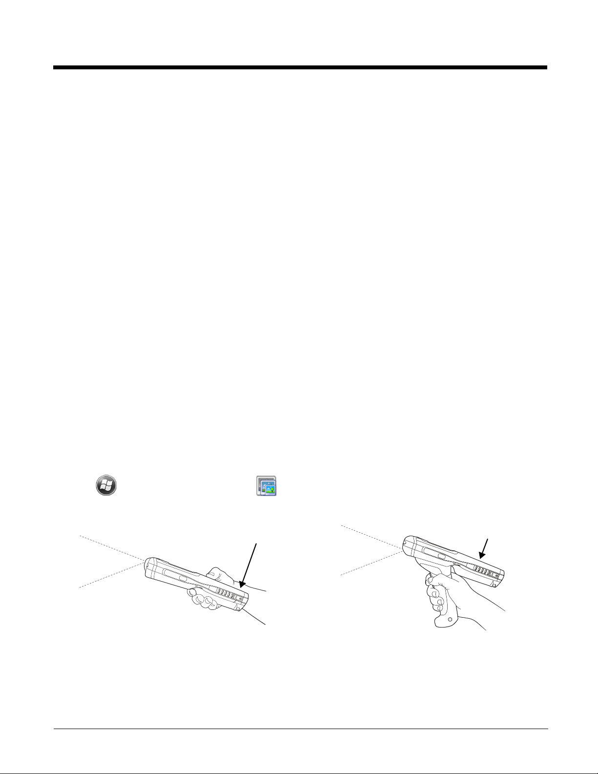
Capturing Images
99EX Models
99GX Models
The image-capture process is an intuitive, split-second operation for experienced users. By following the
basic guidelines, new users can easily develop their own technique and, with practice, quickly learn to
adapt it to different application environments.
Image Preview
When the imaging process is initiated, the touch screen displays a preview of the object. This is a live
video image of what the imager is currently viewing. The live video image has a slightly degraded
appearance compared to the captured image. This is normal.
Scan Key
On all 99EX terminals, the SCAN key captures images.
File Formats
File formats supported for image storage include Bitmap (BMP), JPEG (JPG) and Portable Network
Graphics (PNG). The default file format for images is a grayscale JPG.
Compression
Digital images have a maximum image size of 640 x 480 pixels and may have up to a 256 grayscale
image definition.
The image quality and related file size are determined by the data compression method used by the software application used to take images. The average size of the image file is approximately 4–8K. However, the size of the image depends on the content of the image - the more complex the content, the
larger the file size.
Taking an Image
The following steps are basic guidelines for taking images:
1. Tap > Demos > Imaging Demo .
2. Point the Dolphin terminal at the object.
3. To preview the image, press and hold one of the following:
• the trigger (99GX models only),
• the SCAN key (all models) or
• one of the terminal’s side buttons (all models).
3 - 6
Page 49

4. The touch screen displays a preview of the object, and the decode and scan LEDs light red.
!
5. Adjust the terminal’s position until the object appears on the screen the way you want it to appear in
the image.
6. Hold the terminal still and release the SCAN key, trigger or side button. The scan and decode LEDs
flash red, the screen flashes, and the captured image appears on the screen.
7. Unless otherwise specified by the application in use, the image is saved to the \My Device\My
Documents folder.
Enabling the Aimer
You can enable the aiming pattern for imaging in the Imaging Demo. For details about the aimer, see
Aiming Options on page 3-5.
1. Tap > Demos > Imaging Demo > Setup menu > Aimer.
2. The aiming pattern is now enabled for imaging.
Uploading Images
Image files can be uploaded to a host workstation via Microsoft ActiveSync and a Dolphin communication peripheral or your wireless radio connection.
Note: You can download the most current version of ActiveSync from www.microsoft.com.
Note: Visit the Microsoft Windows 7 Web site for information on how to sync your music, pictures, contacts and
calendars using Device Stage.
Note: Visit the Microsoft Windows Vista Web site for information on how to sync your music, pictures, contacts and
calendars using Windows Mobile Device Center.
We recommend use of Honeywell peripherals, power cables, and power adapters. Use of any non-Honeywell
peripherals, cables, or power adapters may cause damage not covered by the warranty.
3 - 7
Page 50

3 - 8
Page 51

4
Camera Lens
Flashlight/
Camera Flash
ENT
Using the Color Camera
Overview
Dolphin 99EX terminals equipped with a 3.1-Megapixels Resolution color camera with Automated Camera Control (ACC), and an Application Programming Interface (API) provide easy integration of color picture and video capture into business applications. The camera lens and camera flash are located on the
back panel of the terminal.
Note: The following camera and video features are not supported in Dolphin 99GX models.
Taking a picture using the Camera Demo tool
1. Tap > Demos > Camera Demo .
2. Adjust the camera settings using the icon menu at the top of the display screen.
3. Point the terminal's camera lens at the object you
want to capture. The camera lens is located on the
back panel of the terminal.
4. Center the object in the touch screen display.
5. Press the ENT key or tap Snap . The
terminal’s red LED illuminates during picture
capture.
Note: Tap the green arrow to review or edit your pictures.
Tap the green box to exit the picture review/edit
screen.
4 - 1
Page 52

Options
Profile Tab Display Tab
The profile tab allows you to customize your
camera settings, or chose from several
predefined profiles designed to provide the
best picture quality for common tasks.
ENT
Tap Options > Camera.
The Camera Options menu appears. There are five tabs of configurable options accessible from the
Camera Options menu.
Taking a picture using the Windows Embedded Handheld 6.5 Camera tool
1. Tap > Pictures & Videos > Camera
2. Point the terminal's camera lens at the object you want to capture. The camera lens is located on the
back panel of the terminal.
3. Center the object in the touch screen display.
4. Press the ENT key .
5. The touch screen displays the captured photo.
4 - 2
Page 53

Menu
General Tab Slide Show Tab Camera Tab Video Tab
ENT
Tap Menu on the Command Bar to adjust the camera settings, switch to video mode, and access additional camera options.
Item Descriptions
Video Activate Video Mode
Mode Set Mode (i.e., Normal, Burst, or Timer)
Resolution Set Picture Resolution (i.e., QVGA, VGA, SVGA, XGA, UXGA, or QXGA)
Zoom Set Zoom (i.e., x1, x2, or x3)
Flash Set Camera Flash On or Camera Flash Off
Focus Set Focus Off, Focus On, Focus on Trigger, or Fixed-Focus
Brightness Set the brightness setting from +2.0 EV to -2.0 EV in .5 EV increments
Full Screen Switch to full screen mode
Options Set Camera Options, Video Options, Slide Show Options or General Options
Options
Tap Menu > Options. The Options menu contains four screens:
Recording Video
1. Tap > Pictures & Videos > Camera > Menu > Video
2. Point the terminal's camera lens at the object you want to capture.
3. Press the ENT key to start recording.
4. Tap Stop or press ENT to stop recording.
4 - 3
Page 54

4 - 4
Page 55

5
ALT
CTRL
NUM
A B C D E
F G H I J
K L M N O
P Q R S
T
UVWX Y
Z
1
+
@
#
*
F1 F2 F3 F4 F5
F6 F7 F8 F9 F10
F15F14F13F12F11
F17 F18 F19 F20F16
F21 F22 F23 F24 F25
23
456
789
.
0
SFT SP
BKSP
,
SCAN
VOL
PG
TAB
ESC
SEND
END
ENT
☼
ALT
CTRL
A
123
456
789
0
BCDE
FGHIJ
KL MNO
PQRST
UVWXY
Z
SFT
#
!
?
;
@
$&
—
~
`
.
,
*
F6 F7 F8 F9 F10
F15F14F13F12F11
F17 F18 F19 F20F16
F21 F22 F23 F24 F25
BKSP
SP
DEL
+
-
()
=
:
‘
SCAN
VOL
PG
TAB
ESC
ENT
☼
F1 F2 F3 F4 F5
1
SCAN
VOL
PG
TAB
ESC
SEND
END
ENT
☼
3
456
7
.
+
-
/
\
;
—
:
0
,
#
*
@
89
DEF
GHI JKL MNO
PQRS TU V WXYZ
F1F5F2
F6
F3F7F4
F8
SFT SP
BKSP
DEL
ALT
CTRL
ALPHA
2
ABC
34-Key Alpha/Numeric
Keyboard
34-Key Numeric
(Calculator) Keyboard
43-Key Alpha/Numeric
Keyboard
55-Key Full Alpha/
Numeric Keyboard
7
SCAN
VOL
PG
TAB
ESC
SEND
END
ENT
☼
9
456
1
.
+
-
/
\
;
:
—
0
,
#
@
*
23
F1F5F2
F6
F3F7F4
F8
SFT SP
BKSP
DEL
ALT
CTRL
ALPHA
8
DEF
GHI JKL MNO
PQRS TU V WXYZ
ABC
Using the Keyboards
Available Keyboards
There are four keyboard options in the 99EX/99GX series:
All Keyboards Contain the Following:
• Backlit for easy viewing in various lighting conditions.
• Centrally located Scan key for both right- and left-hand operation.
• Color-coding so you can clearly see the most common keyboard combinations.
• Function, navigation, and modifier keys.
Keyboard Combinations
See 34-Key Alpha/Numeric Keyboard Combinations on page 5-6.
See 34-Key Numeric (Calculator) Keyboard Combinations on page 5-9.
See 43-Key Keyboard Combinations on page 5-12.
See 55-Key Keyboard Combinations on page 5-15.
Common Buttons
See Using the Function Keys on page 5-2.
See Using the Modifier Keys on page 5-3.
See Using the Navigation Keys on page 5-3.
5 - 1
Page 56

Using the Function Keys
☼
Blue
☼
BKSP
:
BKSP
BKSP
34-Key
43-Key
55-Key
—
DEL
DEL
34-Key
55-Key
ENT
ESC
SCAN
;
SP
SP
SP
34-Key
43-Key
55-Key
TAB
Name Key Function
Backlight Turns the keyboard backlight on and off.
Flashlight
&
Turns the flashlight on and off. The flashlight is located on the back panel
of the terminal.
Note: The flashlight function is disabled on all 99GX models.
Backspace
(BKSP)
Delete
(DEL)
Moves the cursor back one space each time the key is pressed. If you
are typing text, it deletes the previous character each time it is pressed.
Deletes the next character each time the key is pressed. This key only
appears on the 34-key and 55-key keypad options.
Enter (ENT) Confirms data entry.
Escape
Cancels the current action.
(ESC)
Power Key Puts the terminal in and wakes the terminal from Suspend Mode; see
Suspend Mode on page 1-12.
SCAN Key Activates the scan and “wakes” the terminal from Sleep Mode.
Its position allows convenient one-handed image-taking and/or bar code
decoding.
Space (SP) Moves the cursor one space.
Tab Moves the cursor to the next tab stop or the next control (on a form).
5 - 2
Page 57

Using the Modifier Keys
ALPHA
34-Key
Blue
Red
NUM
43-Key
SFT
SFT
SFT
SFT
34-Key
43-Key
55-Key
VOL
PG
Blue
VOL
Blue
PG
Red
PG
VOL
Name Key Function
ALPHA The ALPHA key enables you to toggle between the alpha and numeric
modes. See ALPHA Key on page 5-5.
Blue
and
Red
The blue and red keys are used in combination with other keys to type
special characters and perform system functions. Each key modifies only
the next key pressed.
Each keyboard is color-coded to indicate the character typed or function
performed when specific keys are pressed immediately after the blue or
red modifier key.
Number
Lock (NUM)
The Number Lock key enables you to toggle between the alpha and
numeric modes. See Number Lock (NUM) Key on page 5-11.
Shift (SFT) The shift key modifies only the next key pressed; it must be pressed
before each key you wish to modify. Shift toggles the keyboard between
uppercase alphabet mode and lowercase alphabet mode.
Press the shift key twice to toggle Caps Lock on and off. When Caps
Lock is toggled on, characters are uppercase; when toggled off,
characters are lowercase.
Using the Navigation Keys
Located in the center of each keyboard for easy access with either hand, the navigation keys navigate
the cursor through application screens.
Key Function
Moves the cursor up one row or line.
Moves the cursor down one row or line.
&
&
&
Raises the volume.
Lowers the volume.
Moves the cursor up one page.
5 - 3
Page 58

Key Function
Red
PG
&
Moves the cursor down one page.
Moves the cursor one character to the right.
Moves the cursor one character to the left.
Note: Additional functionality varies according to the application in use.
5 - 4
Page 59

34-Key Alpha/Numeric Keyboard
1
SCAN
VOL
PG
TAB
ESC
SEND
END
ENT
☼
3
456
7
.
+
-
/
\
;:
—
0
,
#
*
@
89
DEF
GHI JKL MNO
PQRS T U V WXYZ
F1
F5
F2
F6
F3
F7
F4
F8
SFT SP
BKSP
DEL
ALT
CTRL
ALPHA
2
ABC
Backlight\Flashlight key
SCAN key
ALPHA Mode keys
Enter key
Tab key
Escape key
Power key
ALPHA key
Left Navigation\SEND key Right Navigation\END key
Blue key Red key
CTRL\ALT key
Delete key
Backspace key
Space key
Shift key
Down Navigation key
Up Navigation key
Note: The flashlight function ( ) is disabled on all 99GX models.
ALPHA Key
The ALPHA lock key enables you to toggle between the alpha and numeric keyboard modes. On the 34Key Keyboard, numeric mode is the default. Press the ALPHA key once to switch to ALPHA lock mode.
Press the ALPHA key again to exit the ALPHA lock mode.
5 - 5
Page 60

34-Key Alpha/Numeric Keyboard Combinations
Key NUM
(Default)
ESC Escape
Left Left Left Left Left Send
Scan Scan
Right Right Right Right Right End (Phone) Right
Backlight Toggles Keyboard Backlight On/Off Toggles
TAB TabTabTabTabTabTab
Up Up Up Up Up Volume Up Prior
Down Down Down Down Down Volume
Enter Return
Shift-NUM ALPHA Shift-
ALPHA
Blue Red
(Phone)
Flashlight
On/Off (99EX
models only)
Down
Left
Toggles
Keyboard
Backlight On/
Off
Next
1 1!
2 2 @ a,b,c A,B,C
3 3#d,e,fD,E,F
4 4 $ g,h,i G,H,I
5 5 % j,k,l J,K,L
6 6 ^ m,n,o M,N,O
7 7&
(ampersand)
8 8 * (multiply) t,u,v T,U,V
9 9 ( w,x,y,z W,X,Y,Z
Period . (period) > . (period) > * (multiply)
0 0) @
Comma , (comma) < , (comma) < #
p,q,r,s P,Q,R,S
5 - 6
Page 61

Key NUM
(Default)
F1 F1 F1 F1 F1 + F5
F2 F2 F2 F2 F2 - F6
F3 F3 F3 F3 F3 / F7
F4 F4 F4 F4 F4 \ F8
SFT Shift Shift Shift Shift
SP Space Space Space Space ; Space
BKSP Backspace Backspace Backspace Backspace : Backspace
DEL Delete Delete Delete Delete Underscore Delete
Power Off/On
CTRL Control Control Menu
Blue Blue Blue Blue
Shift-NUM ALPHA Shift-
ALPHA
Blue Red
Red Red Red Red
ALPHA Toggles between ALPHA mode and NUM Lock mode
5 - 7
Page 62

34-Key Numeric (Calculator) Keyboard
7
SCAN
VOL
PG
TAB
ESC
SEND
END
ENT
☼
9
456
1
.
+
-
/
\
;
:
—
0
,
#
@
*
23
F1
F5
F2
F6
F3
F7
F4
F8
SFT SP
BKSP
DEL
ALT
CTRL
ALPHA
8
DEF
GHI JKL MNO
PQRS T U V WXYZ
ABC
Backlight\Flashlight key
SCAN key
Enter key
Tab key
Escape key
Power key
ALPHA key
Left Navigation\SEND key Right Navigation\END key
Blue key Red key
CTRL\ALT key
Delete key
Backspace key
Space key
Shift key
Down Navigation key
Up Navigation key
Note: The flashlight function ( ) is disabled on all 99GX models.
ALPHA Key
The ALPHA lock key enables you to toggle between the alpha and numeric keyboard modes. On the 34Key Keyboard, numeric mode is the default. Press the ALPHA key once to switch to ALPHA lock mode.
Press the ALPHA key again to exit the ALPHA lock mode.
5 - 8
Page 63

34-Key Numeric (Calculator) Keyboard Combinations
Key NUM
(Default)
ESC Escape
Left Left Left Left Left Send
Scan Scan
Right Right Right Right Right End (Phone) Right
Backlight Toggles Keyboard Backlight On/Off Toggles
TAB TabTabTabTabTabTab
Up Up Up Up Up Volume Up Prior
Down Down Down Down Down Volume
Enter Return
Shift-NUM ALPHA Shift-
ALPHA
Blue Red
(Phone)
Flashlight
On/Off (99EX
models only)
Down
Left
Toggles
Keyboard
Backlight On/
Off
Next
7 7!
8 8 @ a,b,c A,B,C
9 9#d,e,fD,E,F
4 4 $ g,h,i G,H,I
5 5 % j,k,l J,K,L
6 6 ^ m,n,o M,N,O
1 1&
(ampersand)
2 2 * (multiply) t,u,v T,U,V
3 3 ( w,x,y,z W,X,Y,Z
Period . (period) > . (period) > * (multiply)
0 0) @
Comma , (comma) < , (comma) < #
p,q,r,s P,Q,R,S
5 - 9
Page 64

Key NUM
(Default)
F1 F1 F1 F1 F1 + F5
F2 F2 F2 F2 F2 - F6
F3 F3 F3 F3 F3 / F7
F4 F4 F4 F4 F4 \ F8
SFT Shift Shift Shift Shift
SP Space Space Space Space ; Space
BKSP Backspace Backspace Backspace Backspace : Backspace
DEL Delete Delete Delete Delete Underscore Delete
Power Off/On
CTRL Control Control Menu
Blue Blue Blue Blue
Shift-NUM ALPHA Shift-
ALPHA
Blue Red
Red Red Red Red
ALPHA Toggles between ALPHA mode and NUM Lock mode
5 - 10
Page 65

43-Key Alpha/Numeric Keyboard
ALT
CTRL
NUM
A B C D E
F G H I J
K L M N O
P Q R S
T
UVWX Y
Z
1
+
@
#
*
F1 F2 F3 F4 F5
F6 F7 F8 F9 F10
F15F14F13F12F11
F17 F18 F19 F20F16
F21 F22 F23 F24 F25
23
456
789
.
0
SFT SP
BKSP
,
SCAN
VOL
PG
TAB
ESC
SEND
END
ENT
☼
Backlight\Flashlight key
SCAN key
Number (NUM) Mode keys
Enter key
Tab key
Escape key
Power key
Number (NUM) Lock key
Left Navigation\SEND key Right Navigation\END key
Red key
CTRL\ALT key
Backspace keySpace key
Shift key
Down Navigation key
Up Navigation key
Blue key
Note: The flashlight function ( ) is disabled on all 99GX models.
Number Lock (NUM) Key
The Number Lock key enables you to toggle between the alpha and numeric keyboard modes. On the
43-key keyboard, alpha mode is the default. Press the NUM key once to switch to NUM lock mode. Press
the NUM key again to exit the NUM lock mode.
5 - 11
Page 66

43-Key Keyboard Combinations
Key ALPHA
(Default)
ESC Escape
Left Left Left Left Left Send
Scan Scan
Right Right Right Right Right End
Backlight Toggles Keyboard Backlight On/Off Toggles
TAB Ta b
Up Up Up Up Up Volume Up
Down Down Down Down Down Volume
Shift-ALPHA NUM Shift-NUM Blue Red
(Phone)
(Phone)
Flashlight
On/Off (99EX
models only)
(Phone)
Down
(Phone)
Left
Right
Toggles
Keyboard
Backlight On/
Off
Prior
Next
Enter Return
A a A + (add) F1
B b B 1! F2
C c C 2@ F3
D d D 3# F4
E e E F5
F f F - (subtract) F6
G g G 4$ F7
H h H 5% F8
I i I 6^ F9
J j J F10
K k K @@F11
5 - 12
Page 67

Key ALPHA
(Default)
L l L 7& F12
M m M 8 * (multiply) F13
N n N 9( F14
O o O F15
P p P =F16
Q q Q . (period) > * (multiply) F17
R r R 0) F18
S s S , (comma) < # F19
T t T F20
U u U ;F21
V v V :F22
Shift-ALPHA NUM Shift-NUM Blue Red
W w W _
(underscore)
X x X /F24
Y y Y \F25
SFT Shift Shift
SP Space
BKSP Backspace
Z z Z
Power Off/On
CTRL Control Control Menu
Blue Blue Blue Blue
Red Red Red Red
NUM Toggles between NUM lock mode and ALPHA mode
F23
5 - 13
Page 68

55-Key Full Alpha/Numeric Keyboard
ALT
CTRL
A
123
456
789
0
BCDE
FGH
I
J
KL MNO
PQRST
UVWXY
Z
SFT
#
!
?
;
@
$&
—
~
`
.
,
*
F6 F7 F8 F9 F10
F15F14F13F12F11
F17 F18 F19 F20F16
F21 F22 F23 F24 F25
BKSP
SP
DEL
+
-
()
=
:
‘
SCAN
VOL
PG
TAB
ESC
ENT
☼
F1 F2 F3 F4 F5
Backlight\Flashlight key
SCAN key
Enter key
Tab key
Escape key
Power key
Down Navigation key
Up Navigation key
Left Navigation\SEND key
Right Navigation\END key
Blue key Red key
CTRL\ALT key
Delete key
Backspace key
Space key
Shift key
Note: The flashlight function ( ) is disabled on all 99GX models.
5 - 14
Page 69

55-Key Keyboard Combinations
Key Normal Shift Blue Red
ESC Escape
Left Left Left Send
(Phone)
Scan Scan
Right Right Right End
(Phone)
Backlight Toggle Keyboard Backlight On/Off Toggle
Flashlight On/
Off (99EX
models only)
TAB Ta b
Up Up Up Volume Up Prior
Down Down Down Volume Down Next
Enter Return
SP Space
1 1 ! 11
Left
Right
Toggle
Keyboard
Backlight On/
Off
2 2 @ 22
3#33
BKSP Backspace
4 4 $ 44
5 5 % 55
6 6 ^ 66
DEL Delete
7 7 & 77
8 8 * 88
9 9 ( 99
5 - 15
Page 70

Key Normal Shift Blue Red
SHIFT Shift
Period . (period) > * (multiply) . (period)
0 0 ) 00
Comma , (comma) < _ (underscore) , (comma)
A a A + (add) F1
B b B - (subtract) F2
C c C (F3
D d D )F4
E e E =F5
F f F !F6
G g G @F7
H h H $F8
I i I &F9
J j J _ (underscore) F10
K k K ?F11
L l L \F12
M m M /F13
N n N ~F14
O o O 'F15
P p P
Q q Q : F17
R r R ‘ (back quote) F18
S s S “ (quotes) F19
T t T " (back quotes) F20
;
F16
U u U u or U F21
5 - 16
Page 71

Key Normal Shift Blue Red
V v V v or V F22
W w W w or W F23
X x X x or X F24
Y y Y y or Y F25
Power Off/On
CTRL Control Menu
Blue Blue
Red Red
Z z Z z or Z z or Z
5 - 17
Page 72

5 - 18
Page 73

6
System Settings
Overview
Customized settings are available on the System Settings menu. Tap > Settings and the settings
screen opens.
Icon Description
Bluetooth Configures the Bluetooth radio. See Working with the Bluetooth Radio on page 9-1.
Clock &
Alarms
Lock Password protect the terminal to limit access to the terminal.
Sounds &
Notifications
Home Customize the look and the information displayed on the Home screen.
Connections Establishes network connections settings. See Connections Menu on page 7-1.
Personal Customizes buttons, and set SIP options. See Personal Menu on page 6-3.
Set the system clock, date, time and schedule alarms. See Clock & Alarms on page
6-2.
Set the sound volume, enable or disable sounds for specific actions, set sound
parameters for system notifications and enable or disable vibrator notification.
6 - 1
Page 74

Icon Description
System Adjusts system settings. See System Menu on page 6-7.
Microsoft My
Phone
Synchronizes your phone’s contacts, calendar, tasks, text messages, music, photos,
videos, and other documents with your My Phone account at
http:\\myphone.microsoft.com.
Clock & Alarms
The Clock & Alarms settings can be accessed from the Home screen or the Settings Menu.
1. On the Home screen, tap the line that displays the time and date
OR
Tap > Settings > Clock & Alarms,
2. The Clock Settings screen appears. This setting sets the system clock. All scheduled items run
according to this setting.
Tap the arrow to the right of the time zone to open the drop down menu. Select the appropriate time
zone from the menu. Set the correct time and date in the remaining fields and tap OK to save.
6 - 2
Page 75

Personal Menu
To access the Personal Menu, tap > Settings > Personal. The screen opens displaying the Personal Menu.
Icon Description
Buttons Program the side buttons to perform specific tasks. See Buttons on page 6-3.
Owner
Information
Phone This Phone icon is present on Dolphin models equipped with WWAN radio (GSM/
Enter your contact information (e.g., name, company, address, telephone number
and E-mail address).
UMTS/GPRS/EDGE) capabilities. Tap this icon to set up user parameters. See
Changing the Phone Sounds, Security, Services, and Network Options on page 8-
6.
Buttons
The Buttons setting programs certain keyboard buttons to launch applications or execute commands.
Enable HotKeys
Default Buttons setting assignments are inactive until you enable the HotKeys Power Tool.
Tap > Power Tools and tap the HotKeys icon once. HotKeys is enabled, and the button
assignments in the Buttons setting are active.
For more information about the HotKeys Power Tool, refer to the Dolphin Power Tools User’s Guide,
which is available for download from the web at www.honeywellaidc.com.
6 - 3
Page 76

Changing Button Assignments
1. After HotKeys is enabled, tap > Settings > Personal > Buttons .
Note: The buttons that appear on this window are the only buttons that can be programmed via the Buttons setting.
You cannot add buttons to this window.
2. To change button assignment, tap on the name of the button in the Button column, and then select
a program or command in the Assign a program drop down list.
3. Tap OK to save.
4. Press the button to verify that the program is launched or action performed.
Available Applications
The Assign a program list contains the applications installed on the terminal. If there is a program
installed that you would like to see in this list, paste a Shortcut to the program in the \\Windows\Start
Menu\Programs folder. For instructions about creating shortcuts, see Using File Explorer on page 6-5.
Additional Functions
The Assign a program list also contains the following commands:
Command Description
<Context Menu> Performs the same function as tap-and-hold to open the context menu for the control.
<Input Panel> Opens the soft input panel.
<Left Softkey> Opens the menu or performs the action displayed on the left side of the Command bar.
<Scan1> Activates the scanner/imager.
<None> Nothing happens when the button is pressed.
<OK/Close> Performs the same function as tapping OK on the screen.
6 - 4
Page 77

Command Description
<Right Softkey> Opens the menu or performs the action displayed on the right side of the Command bar.
<Scan2> Activates the scanner/imager.
<Rotate Screen> Changes the screen orientation from portrait to landscape.
<Scroll Down> Scrolls down in the open application.
<Scroll Left> Scrolls left in the open application.
<Scroll Right> Scrolls right in the open application.
<Scroll Up> Scrolls up in the open application.
<Start Menu> Opens the Start menu.
Using File Explorer
If you do not see the program listed, you can either use File Explorer to move the program or ActiveSync
on the workstation to create a shortcut to the program and place the shortcut in the Start Menu folder.
Note: We recommend that you Copy and Paste Shortcut so that you do not alter your program configurations by
accident. Using Copy and Paste Shortcut (as opposed to Cut and Paste) ensures that the program files
remain where they need to be for the system to find them to perform system functions.
1. Tap > File Explorer , and navigate to the program (My Device > Program Files).
2. Tap and hold on the program, then tap Copy on the pop-up menu.
6 - 5
Page 78

3. Navigate to the Windows folder and open the Start Menu (My Device > Windows > Start Menu >
Programs), tap and hold a blank area of the window, and tap Paste Shortcut on the pop-up menu.
Note: If there is no blank space available in the window, tap on Menu > Edit > Paste Shortcut.
4. Tap to verify that the program now appears on the Start menu.
Using ActiveSync on the Workstation
Here, you are performing the same basic process as on the terminal, except that you are using the
Explore utility (Windows Explorer) to copy and paste the shortcut.
1. Open ActiveSync > Explore and navigate to the program.
2. Right-click on the program and select Create Shortcut.
3. Select the shortcut, right-click, and select Cut.
4. Navigate to the Start Menu folder (Windows > Start Menu > Programs).
5. Right-click on an empty area and select Paste Shortcut.
6. On the terminal, tap the Start menu.
7. Verify that program appears.
6 - 6
Page 79

System Menu
The System menu enables you to verify and sometimes alter system parameters. To access the System
menu, go to Start > Settings > System. Tap the appropriate icon to open that system setting.
Icon See Page
About See About on page 6-8.
Backlight See Backlight on page 6-9.
Battery See Battery on page 6-10.
Certificates See Certificates on page 6-10.
Customer
Feedback
Encryption See Encryption on page 6-11.
Error
Reporting
See Customer Feedback on page 6-10.
See Error Reporting on page 6-11.
6 - 7
Page 80

Icon See Page
External
GPS
Five Volt
Control
Smart
Sensors
Managed
Programs
Memory See Memory on page 6-15.
Power See Power on page 6-16.
RIL See RIL on page 6-16.
See External GPS on page 6-11.
See Five Volt Control on page 6-12.
See Smart Sensor on page 6-12.
See Managed Programs on page 6-14.
Regional
Settings
Remove
Programs
Screen See Screen on page 6-18.
Task
Manager
See Regional Settings on page 6-16.
See Remove Programs on page 6-17.
See Task Manager on page 6-19.
About
The About system setting displays specific information about the terminal. It contains three screens:
Version Screen Displays the information about the software, operating system, and processor.
Device ID Screen Displays the information the terminal uses to identify itself to other devices. It can be important
to know this information if the Dolphin terminal is going to be part of a networked system of
devices.
Device name: Displays the system’s default name. The device name is used by ActiveSync.
Description: Displays the description of the device ID.
Copyrights Screen: Displays important copyright information.
6 - 8
Page 81

Backlight
Bat t ery Power Ta b Ex t ernal Pow e r Tab Br i g htnes s Tab
The Backlight system setting enables you to customize backlight functionality for the display. The backlight for the color display is user-defined. The Backlight system setting screen contains three tabs: Battery Power, External Power, and Brightness.
Tap > Settings > System > Backlight.
The Battery Power tab determines the backlight timeout when the terminal is running on battery power.
The External Power tab determines the backlight timeout when the terminal is running on external
power.
The options on the power tabs are the same.
Turn off backlight: Select how many minutes you want to elapse before the backlight
automatically turns off.
Turn on backlight: Select this option if you want the backlight to turn on when the button is
pressed or the touch screen is tapped.
The Brightness tab determines the backlight intensity. Move the slider to set the intensity of the backlight. The default is 8. The Auto adjust backlight option allows the light sensor to automatically adjust
the display brightness based on the ambient light. The Auto adjust backlight option is also accessible
from the Smart Sensors applet, see Smart Sensor on page 6-12.
6 - 9
Page 82

Battery
Battery Status Tab Log Config Tab
When external power is
supplied to the terminal,
“Battery Time to Full” is
listed. When power is
supplied by the battery
pack, “Battery Time to
Empty” is listed.
Intermediate Screen Personal Screen Root Screen
The Battery system settings menu contains two tabs: Battery Status and Log Config. The Battery Status tab provides the status of the main battery pack (e.g., Battery Time to Full or Battery Time to Empty,
Voltage, Current, Temperature, Chemistry, and Serial Number). The Log Config Tab allows you to configure the BatteryLogFile.
Tap > Settings > System > Battery
Certificates
Certificates shows you the certificates that are recognized by the operating system. It contains three
screens.
Customer Feedback
Customer Feedback gives you the option to participate in the Microsoft Customer Experience Improvement Program.
6 - 10
Page 83

Encryption
Access Screen Hardware Screen Programs Screen
Encryption gives you the option of encrypting files placed on storage cards so that those files cannot be
read by any other device.
Error Reporting
Error Reporting gives you the option of enabling or disabling the error reporting function of Windows
Embedded Handheld 6.5.
External GPS
External GPS determines which port a third-party GPS software application can use to access the GPS
receiver.
Note: You need the installation parameters from the GPS manufacturer to configure the connection.
6 - 11
Page 84

Five Volt Control
Five Volt Control gives you the option to manually enable 5V output to supply power to an external
device. By default, 5-Volt Output automatically turns on when AC power is applied to the terminal. If you
want to use a USB memory stick without AC power, then you must manually turn on the 5-Volt Output.
Do not leave 5-Volt output enabled when you are not using it to supply power to an external device.
Smart Sensor
The Smart Sensor configuration utility enables you to configure the Dolphin’s integrated accelerometer,
light, and proximity sensors.
Tap > Settings > System > Smart Sensor.
Motion Settings
Motion Settings enable you to customize how the terminal responds to motion and object orientation for advanced
power management.
Display Settings enables or disables Auto Display
Orientation. When enabled, the Dolphin's display
automatically switches between portrait and landscape
depending on how you hold the terminal.
6 - 12
Power Management Settings customize how the terminal
responds to object orientation and motion.
• Save power by turning off the display or suspending the
terminal when it is placed face down.
• Modify the Motion Detection settings to wake the terminal
from suspend mode or prevent the terminal from entering
suspend mode when motion is detected.
Page 85

Light Settings
Event Track displays an event log summary of detected free
fall events exceeding 2 ft. over 250 ms. The summary includes
the time, date, and duration of the most recent 50 events.
Several options are provided for audible notification of free fall
events.
Light Sensor Settings customize how the terminal responds
to the environmental lighting conditions in which the terminal is
being used.
• Enable Display Backlight Adjustment automatically
adjusts the brightness of the display screen depending on
the environmental lighting conditions.
• Enable Automatic Keypad Backlight automatically turns
the keypad backlight on or off depending on the
environmental lighting conditions.
Proximity Settings
Proximity Sensor Settings customize how the terminal
responds to objects detected close to the touch screen display
(e.g., a person's face, carrying holster, or tabletop). When
enabled, the terminal automatically turns the display off when
it detects an object in close proximity to the entire touch panel
display. The display turns back on when the sensor detects the
removal of the object.
6 - 13
Page 86

Accelerometer Calibration
Ta p Start to calibrate the integrated accelerometer sensor
used for motion detection. When calibration is complete, the
"Accelerometer Calibration Finished!" message window
appears.
Managed Programs
Managed Programs are a list of programs that are managed if enrolled to enterprise domain. Managed
Programs is the client-side that works with the server product System Center Mobile Device Manager
(MDM). MDM consists of MDM Gateway Server and one or more computers that run MDM Device Management Server; MDM Enrollment Server; and Microsoft SQL Server® 2005 databases.
It lets system administrators:
• provide an authenticated connection to LOB applications, managed Group Policy, and application
packages.
• use Group Policy and software packages to manage the enrolled Windows phones (enforce policy,
wipe devices, etc.).
• manage the requests for and retrieving of certificates for devices and for creating the Active Directory®
Domain Service objects that represent these devices. By using these objects, you can manage the
devices as if they were members of a domain.
6 - 14
Page 87

Memory
The Memory applet shows the capacity and usage of the Storage and Program portions of the Flash file
system. The Storage portion includes the IPSM folder, which can be detailed under the Storage Card
tab. When the Program portion becomes too full, you can use the Task Manager to remove any unnecessary tasks.
Main Screen
This screen displays the usage statistics of the flash
memory.
Storage Card Screen
This screen displays the current capacity and usage statistics of the selected memory type: IPSM or Storage
Card.
Select the memory type from the drop-down list. IPSM is
selected by default.
Total storage card memory = The total MB of memory
capacity of IPSM or Storage Card.
In use = The MB currently being used.
Free = The MB that is still available for use.
IPSM—Short for Internal Persistent Storage Manager. Data or programs stored in the
IPSM are not affected when the operating system is upgraded. Autoinstall programs,
for example, are stored in \\IPSM\Honeywell\Autoinstall so that they are always
installed after an operating system upgrade or factory reset.
Storage Card—You can install one memory card in Dolphin terminals (see Installing
a Memory Card on page 2-17). If a storage card is installed in the terminal, you can
select it in the drop-down list and see capacity and usage statistics for the card.
6 - 15
Page 88

RIL
The RIL Information screen displays useful statistics for the GSM WAN Voice module (PH8).
To verify whether or not the GSM radio is enabled, check the Dolphin Wireless Manager (see page 7-6).
Power
Power system settings contains two tabs: Battery and Advanced
Tap > Settings > System > Power
Battery Tab
The battery tab displays the power level status of the
main battery and the status of the backup battery.
Note: The Backup Battery gauge registers either 0% or 100%.
The percentage is not an indication of the level of charge
remaining on the backup battery. An installed and
functional battery registers 100%. A total discharge or a
battery error registers 0%.
For detailed information on the main battery pack, see
Battery on page 6-10.
Advanced Tab
Determines power time-outs.
For On battery power, select from the drop-down list, the
number of minutes of inactivity you want to pass before the
terminal powers off when running on battery power.
For On external power, select from the drop-down list, the
number of minutes of inactivity you want to pass before the
terminal powers off when running on external power.
Note: When the terminal “powers off”, it enters Suspend Mode, see page 1-12 for additional information.
Regional Settings
Regional Settings enables you to customize the appearance and formatting to your geographic region.
Specifically, you can customize numbers (i.e., number of decimal places allowed), currency (i.e.,using
the $ or € symbol), time, and date. These specifications apply to all screens, including the Home screen.
The Region tab displays an overview of the region selected in the drop-down list at the top.
6 - 16
Page 89

The terminal is loaded with a number of pre-programmed regional settings. Select one from the list and
the results appear on the screen. To see specific settings or to change a specific setting, tap on one of
the tabs, make the change, and tap OK to save it.
Remove Programs
Remove Programs enables you to remove programs installed on the terminal. Any program (usually CAB
or DLL files) stored in the \\IPSM\Honeywell\Autoinstall folder re-installs after a software upgrade or a
factory reset. If a program is manually removed using the Remove Programs application, the program
does not re-install on a hard or soft reset.
Note: A program (file) does not automatically install if it is added to the \\IPSM\Honeywell\Autoinstall folder and a
hard or soft reset is performed. For information on program installation, see Installing Additional Software on
page 7-10.
For information about the system resets, see Resetting the Terminal on page 1-11. See Honeywell support for more information on how to perform a factory reset.
1. Tap Remove Programs. In the list, select the program you want to remove.
2. Tap Remove. The following message appears:
3. Tap Yes. Wait while the program is removed.
4. Verify that the program no longer appears in the list.
6 - 17
Page 90

Screen
The Screen system setting contains three screens: General, Clear Type, and Text Size.
General Screen
Orientation
The General screen enables you to set the dynamic screen
rotation. Three choices of screen orientation are supported:
Portrait, Landscape (right-handed), and Landscape (lefthanded).
Align Screen
The General Tab also allows you to re-align the screen.
You need to re-align the screen if tapping buttons or icons with
the stylus no longer seems to work appropriately.
Tapping Align Screen brings up the align screen window
where you are guided to tap a target several times. This recalibrates how the touch screen receives input.
• Alignment should always be performed with a stylus
designed for touch panel applications. The small point is
required for accurate calibration.
• Press the stylus firmly into the center of the cross-hair target
once and release. Do not “double-tap” the target.
ClearType Screen
The display supports ClearType font rendering, which is a
Microsoft technology that dramatically increases the readability
of text on LCD displays.
To enable Clear Type font rendering, select Enable ClearType
and tap OK.
For more information about Clear Type font rendering, visit:
www.microsoft.com/typography/WhatIsClearType.mspx.
6 - 18
Page 91
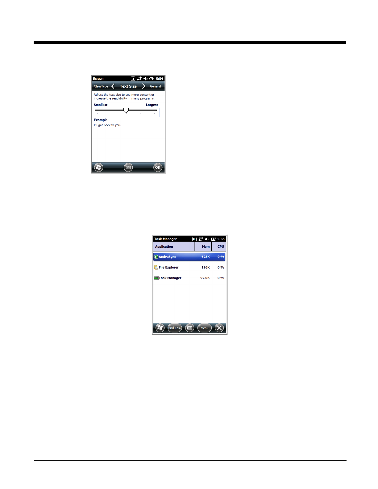
Text Size Screen
The Text Size screen enables you to perform font scaling within
certain views of the:
• Home screen,
• Contacts,
• Calendar,
• Messaging, and
• Tasks.
Font scaling means that you can increase or decrease the
point size of the font on application windows.
To change the font size, move the slider toward Smallest or
Largest. The Example text changes to reflect the font change.
Ta p OK to save the new font size setting.
Task Manager
The Task Manager provides information about applications and processes running on your mobile computer. You can use the Task Manager to monitor the memory and CPU usage of specific applications and
processes. Check the Task Manager when you are receiving out of memory errors or when the mobile
computer is running slowly.
6 - 19
Page 92

Using the Task Manager
Applications To view the status of the programs running on your
Note: Anytime you stop a running program, it frees up memory. To free up memory, return to the running
program, save your data, and close the application.
Processes To view information about the processes running on the
mobile computer, tap the Menu button at the bottom of
the screen, then tap View > Applications.
From the application list, you can:
• Tap and hold on an application, then tap Switch To on
the pop-up menu.
• Tap and hold on an application, then tap End Task or
End All Tasks on the pop-up menu.
mobile computer, tap the Menu button at the bottom of
the screen, then tap View > Processes.
6 - 20
Page 93

7
Communication
Connections Menu
The Connections system setting provides access to the terminal’s various wireless communication
options.
Icon Tapping this icon…
Beam Enables infrared communication.
Connections Opens Microsoft’s connections manager.
Dolphin
Wireless
Manager
Domain
Enroll
USB to PC Enables advanced wired USB to PC communication via sync software. See
Network
Cards
Manages the wireless radios installed in the terminal. See Dolphin
Wireless Manager
Note: The Dolphin Wireless Manager icon may not appear on the Connections
menu on terminals running Microsoft Windows Embedded Handheld 6.5
Classic. For information on how to access the Dolphin Wireless Manager,
see page 7-6.
Opens the Enrollment screen for connecting your phone with company resources.
Note: System administrator password is required for domain enrollment.
Connecting and Synchronizing the Terminal and Workstation on page 7-8.
Manage Network card settings.
on page 7-6.
See Receiving Data on page 7-3.
See Connections Manager on page 7-4.
Note: All server-assigned IP addresses use Dynamic Host Configuration Protocol (DHCP).
7 - 1
Page 94

Using the IrDA Port
IrDA Port
Using the IrDA port, you can send and receive data between the terminal and other devices equipped
with infrared. This can include, but is not limited to, Windows Embedded Handheld information such as
Contacts and Tasks, as well as software upgrades.
IrDA Port Location
Note: Your Dolphin model may differ from the models illustrated; however, the features noted are standard for all
99EX and 99GX models unless otherwise indicated.
To send or receive, the IrDA ports of both devices - whether it is two terminals, or a terminal and a host
device - must be aligned with each other and within a close range. The maximum data transfer speed is
115 Kbps.
Sending Data
1. Align the IrDA ports.
2. Open the program where you created the item you want to send and locate the item in the list.
You can also beam files, but not folders, from File Explorer.
3. Tap and hold the item and select Beam File.
7 - 2
Page 95

4. The IrDA port searches for a receiving IrDA port in the vicinity. The selected device reads “Pending.”
5. When the IrDA port finds the aligned IrDA port, it immediately starts sending the selected file. The
selected device reads “Sending.”
6. When the file transfer is complete, the selected device reads “Done.”
Receiving Data
The Beam Setting must be set to receive all incoming beams from other infrared devices.
1. Verify that beam settings are set to receive. Tap > Settings > Connections > Beam. The
Beam Settings window should appear as follows:
2. Align the IrDA ports.
3. Have the owner of the other device send the data to you.
4. Your terminal automatically begins receiving the data.
5. A popup message appears asking if you want to save the incoming file.
6. Tap Yes to receive the file.
7 - 3
Page 96

Connections Manager
Microsoft’s Connections Manager sets up multiple network connections to Internet Service Providers
(ISPs) via external modem.
Do NOT enter connection parameters in the Connections Manager if:
• you are using one of the on-board wireless radios to connect to a network. The Dolphin terminal uses
the settings from each radio’s configuration utility to connect. The connections manager is used
primarily to setup WAN modem dial up connections.
• you are using Wireless Zero Config. By default, WZC is disabled on Dolphin terminals.
To Access the Connections Manager
Tap > Settings > Connections > Connections .
Tasks
The Tasks screen enables you to initially configure, and then manage network settings when using a
modem. Select an item in this list and then complete the setup screens that follow with the appropriate
information for your network.
My ISP
The links under this heading enables you to add and manage modem connections to an ISP. To complete the setup screens, obtain the following information from your ISP:
• ISP dial-up access telephone number
•User name
• Password
• TCP/IP settings
My Work Network
These links enable you to establish the following connections types:
• Modem
• Virtual Private Network (VPN)
7 - 4
Page 97

• Proxy server connection
Note: If you are connected to your ISP or private network during synchronization, the terminal should
download the proper proxy settings during synchronization with the workstation. If these settings are
not on your workstation or need to be changed, ask your ISP or network administrator for the proxy
sever name, server type, port, type of Socks protocol used, and your user name and password.
To complete the setup screens, obtain the network parameters from your system administrator.
Modify an Existing Connection
Manage Existing Connections appears on the Connections tab after at least one network connection
has been established.
Tap Manage Existing Connections on the Horizontal scroll and follow the setup screens.
Advanced
The Advanced screen enables you to select the default network, dialing rules, and IP address exceptions
for modem connections.
Note: You should not need to change Advanced settings because most ISPs now use DHCP addresses.
7 - 5
Page 98

Dolphin Wireless Manager
If applicable, information about
the radio appears when the
radio is activated.
These buttons show you the
state of the radio.
The Dolphin Wireless Manager provides a centralized interface that enables and disables all the onboard radios. Each radio has its own configuration program. The Dolphin Wireless Manager also provides shortcuts to the configuration utilities for each radio.
Ta p on the Home screen to access the Dolphin Wireless Manager.
OR
1. Tap once on the Title bar to access the Horizontal Scroll bar.
2. Tap .
3. Select, “Dolphin Wireless Manager”.
Dolphin Wireless Manager Window
Note: Not all Dolphin models are equipped with the same radio types. Your Dolphin Wireless Manager Window may
differ slightly from what is illustrated depending on your Dolphin model.
Enabling the Radios
1. Tap on the Home screen to access the Dolphin Wireless Manager.
2. Tap anywhere inside the rectangle of the radio you want to enable.
7 - 6
Page 99

3. The radio begins activating.
4. When the radio is activated (i.e., transmitting a signal), the OFF button changes to ON.
Note: If applicable, information about the radio appears in the rectangle.
Accessing Radio Configuration Utilities
Each radio has its own configuration utility that you can access by tapping Menu on the tile bar.
Radio Type Menu Option
802.11a/b/g/n Tap WLAN Settings and the Honeywell WLAN Security
Supplicant opens.
The Honeywell WLAN Security Supplicant User’s Guide is
available for download from the Dolphin 99EX or 99GX product
page at www.honeywellaidc.com.
Bluetooth Tap Bluetooth Settings and the Bluetooth Settings open.
For details, see Working with the Bluetooth Radio on page 9-1.
GSM/HSDPA+/UMTS/GPRS/EDGE
(voice + data)
Ta p Phone Settings and the Phone opens.
For details, see Working with Wireless Wide Area Networking
on page 8-1.
GSM/HSDPA+/UMTS/GPRS/EDGE
and CDMA/1xRTT/EVDO
(data only)
Ta p Gobi Settings and the Gobi Manager opens.
For details, see Accessing the Gobi Manager to Set Up or
Change Network Settings on page 8-12.
7 - 7
Page 100

Network Cards
!
The Network Cards screen allows you to set and configure the type of Network Adapter the Network
card in the terminal uses. You can modify the adapter settings (e.g., Name Servers or IP address) by
tapping on the adapter type or highlighting the adapter and tapping Edit at the bottom of the screen.
Connecting and Synchronizing the Terminal and Workstation
To synchronize data between the terminal and the workstation, ActiveSync (version 4.5 or higher) or
Windows Mobile Device Center must be installed and configured for the appropriate communication type
on the host workstation (Windows-based PC) and the Dolphin terminal. Dolphin terminals ship with
ActiveSync already installed. Therefore, if ActiveSync is already installed on the host workstation, you
just need to connect the Dolphin terminal to the host workstation (via Dolphin peripheral) to initiate communication.
If ActiveSync (4.5 or higher) or Windows Mobile Device Center is not installed on the host workstation,
you can download and install the most current version of the software from the Microsoft Web site
(http://go.microsoft.com/fwlink/?LinkId=147001).
Note: ActiveSync on your Dolphin terminal works with Windows Mobile Device Center on host workstations running
Windows Vista or Windows 7 and with ActiveSync on host workstations running Windows XP. For detailed
information on ActiveSync and WMDC visit the Microsoft Windows Phone Web site.
When communicating via ActiveSync or Windows Mobile Device Center, your terminal is designed to be
connected to the host workstation with a communication peripheral sold/manufactured by Honeywell, such as
the charge/communication cable. Use of any peripheral not sold/manufactured by Honeywell may cause
damage not covered by the warranty.
Capabilities
• Back up and restore your device data.
• Copy (rather than synchronize) files between your device and workstation.
• Control when synchronization occurs by selecting a synchronization mode. For example, you can
synchronize continually while connected to your workstation or only when you choose the synchronize
command.
7 - 8
 Loading...