

Volume Control
Blue
VOL
Blue
PG
Displays the network carrier
from the SIM card.
Displays the most
recent calls.
Toggles the touch screen
keypad ON or OFF.
Menu
&
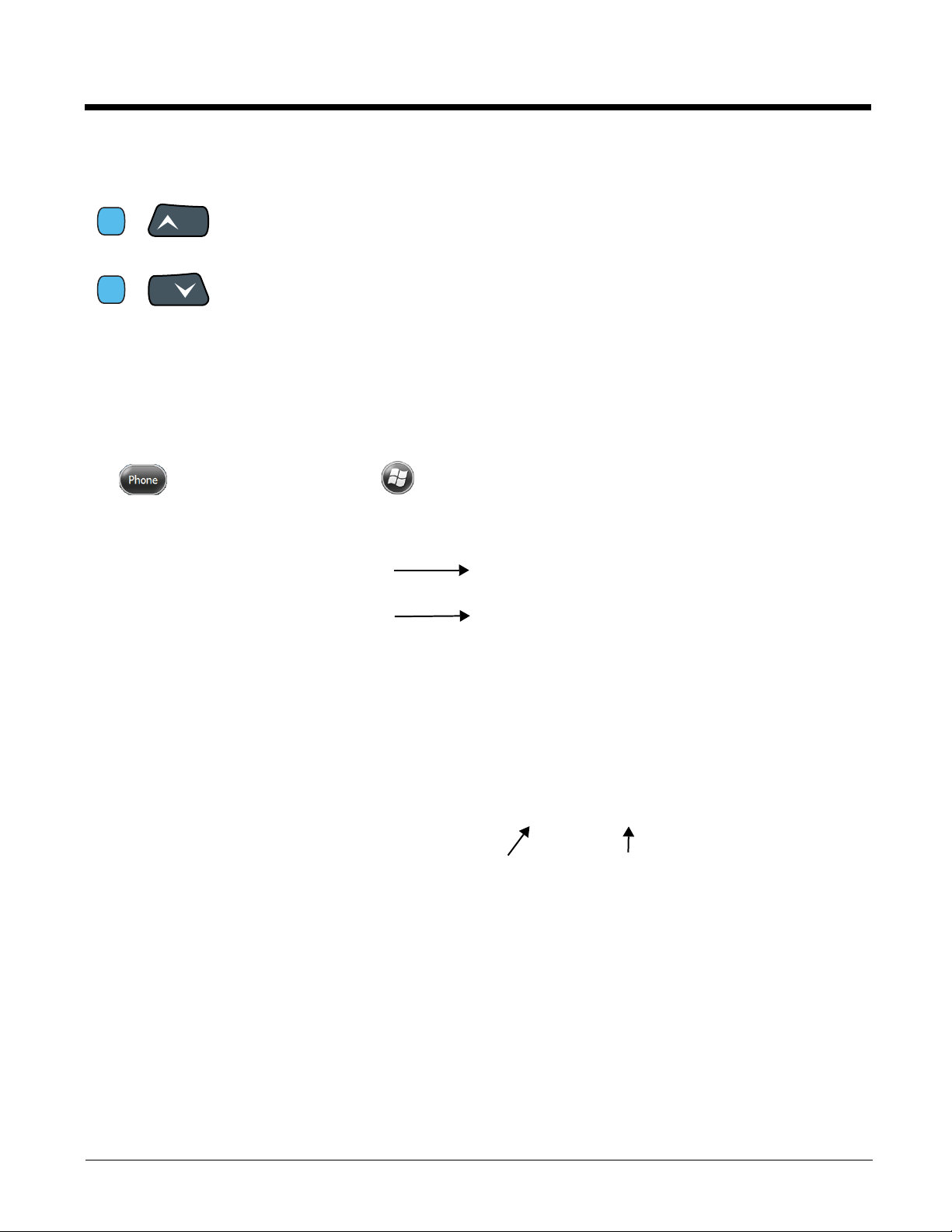
Use the Dolphin keyboard to adjust the volume.
To raise the volume, press the Blue modifier key + up arrow.
To lower the volume, press the Blue modifier key + down arrow.
&
Or
Press the up or down arrow on the Volume Control button on the right side of the
device to adjust the volume of the active speaker, see Volume Control Button on
page 3-10.
Accessing the Dialer Window
Note: The WWAN radio must be active for voice communication, see Enabling the WWAN Radio on page 9-5.
Tap on the Home screen or tap > Phone to open the Phone dialer.
Dialing
Once the dialer window is open, you can dial out two ways:
• Tap the buttons on the dialer window.
• Use the physical keyboard (when the keyboard is in numeric mode).
9 - 6
Sending Calls
SEND
END
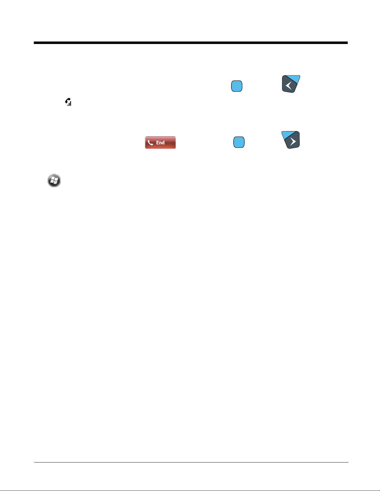
After the number is dialed, tap Talk or press the Blue + Send key .
Note: The icon indicates that the phone is in use.
Ending Calls
While the phone call is live, tap End or press the Blue + End Key .
Accessing Voice Mail
Tap > Phone > Speed Dial > Voice Mail > Call.
Note: Update the voice mail retrieval number by turning the phone OFF and then ON via the Dolphin Wireless
Manager, see Enabling the WWAN Radio on page 9-5.
View Options
From the view menu, you can modify the display screen to show Calls and Contacts, All Calls or Speed
Dial numbers.
Tap Menu > View.
Setup Options
The Options menu contains four setting widows: Sounds, Security, Services, and Network.
Tap Menu > Options.
Sounds
The Sounds screen enables you to customize the:
• Ring type (e.g., Ring, Increasing ring, Ring once,
Vibrate, Vibrate and ring, Vibrate then ring or None)
• Ring tone
• Keypad tone (e.g., Long, Short, or Off)
9 - 7

Security
Services
The Security screen provides access to establish or
change your security PIN. Check the box next to,
“Require a PIN when the phone is used” to enable the
PIN security feature.
For each service, the phone reads settings from the
network stored on the SIM card and then displays the
available options from the carrier on the screen. To
customize the settings, select it from the list and tap
“Get Settings”.
9 - 8

Network
You can find, select, and set your preferred network
order from the Network screen.
Data Communication (GSM/HSPA+ Global Radio Dolphin Models)
You set up data communication via the Connections Manager. The carrier on the SIM card is the ISP.
System Requirements
• The GSM radio must be enabled; see Enabling the WWAN Radio on page 9-5.
• You must have an active SIM card with a DATA plan installed; see SIM Card Installation on page 9-3.
Information Requirements
You must have from the SIM card carrier:
• The APN (access point name).
• The user name and password of the account.
Establishing Data Communication
1. Tap > Settings > Connection > Connections .
2. Under My ISP, tap Add a new modem connection.
9 - 9

3. Enter a name for the connection. Select Cellular Line (GPRS) as the modem. Tap Next.
4. Enter the Access point name. Tap Next.
5. Enter the user name and password from the account. Tap Finish.
9 - 10

6. The connection you just created should appear in the list on the modem tab.
7. Tap and hold on the connection. Select Connect on the popup menu.
8. The network icon in the Title bar indicates the GSM radio is attempting to connect .
Note: When the device is on a 2G (EDGE/GPRS) network, a data connection failure occurs if the phone is in
use for a voice call while attempting a data connection. Simultaneous voice and data use is only
supported if the device is on a 3G network. In 2G mode, a voice call takes precedence over data
connections. Active data connections are placed in "park" mode automatically and the data is "retrieved"
when the voice call ends.
9. When the connection is complete, the network icon changes to: .
10. You can now send data over GSM.
Ending the Data Connection
By default, the data connection will disconnect after a certain amount of time passes without use.
This period of time is determined by ISP.
To end the data connection manually, tap the network icon in the Title bar and select Disconnect on
the popup bubble.
Manual Network Selection
You can select Automatic or Manual network selection. The Phone defaults to Automatic network selection.
9 - 11

1. When an active SIM card is inserted in the terminal, tap
> Settings > Personal > Phone > Menu > Options.
2. Select the Network tab.
3. Under Network selection, select Automatic (the default selection) or Manual.
a. If you select Manual, the Phone searches for available networks.
b. The found networks appear.
c. Select a new network and tap OK. The Phone registers on the new network and the Network tab
appears.
d. To switch to another network, tap the now active Select button and the process repeats.
4. To switch back to automatic roaming, select Automatic under Select networks and tap OK.
9 - 12

Data Communication GSM/CDMA Dolphin Models
Gobi Manager
The Gobi Manager enables you to see real time status of the radio, setup your Network selection, view
you’re profile and scan for networks. The Gobi Manager contains four tabs: Status, Setup, Profile, and
About.
1. Tap on the Home screen to access the Dolphin Wireless Manager.
2. Tap Menu.
3. Select Gobi Settings.
Status Tab The Status tab contains the real time radio status
information including:
• The power status of the radio (e.g., ON or OFF)
• The received signal strength intensity (RSSI)
• The radio mode used (e.g., GSM, UMTS, EVDO
or 1xRTT)
• The network firmware used
• The IP Address assigned
You can also turn the radio ON or OFF and Start or
Stop a data session from the Status tab.
Setup Tab The Setup tab allo ws you to view and customiz e the
Network Setup including:
• The Network Firmware (e.g., AT&T, Verizon,
Sprint, or T-Mobile)
• The SIM Slot accessed
• The Access Point Name (APN)
• The User name of the account
• The Password of the account
• Enable or Disable Automatic Data Sessions
• Activate Over the Air (OTA)
9 - 13

Profile Tab The Profile tab allows you to see Radio capability
information and network statistics including:
• Radio Hardware and Software versions
• Radio and SIM identification numbers
• Serving network connection type and state
• Available radio interfaces for the current serving
network
About Tab Displays copyright and version information for the Gobi Connection Manager.
Establishing Data Communication
1. Tap on the Home screen to access the Dolphin Wireless Manager.
2. Tap Menu and then select Gobi Settings.
3. From the Setup tab, select the carrier and enter user information (GSM only).
Note: An installed SIM card is required and the SIM slot option must be set to 0.
4. Check the Auto Start Data Session check box to automatically start the data session.
5. Tap the Apply button. The Connection Manager automatically switches to the Status Tab.
6. Tap the Radio Power ON button.
”
7. When the radio connects to the network, the status changes to “Registered
displayed.
8. If Auto Start Data Session was checked on the Setup tab, the state automatically changes from
“Registered” to “Data Session Open” and an IP address appears. If Auto Start Data Session was
not selected, then the Data session can be started manually by tapping Start Data Session button
from the Status tab.
and a signal strength is
9 - 14

10
Working with the Bluetooth Radio
Enabling the Bluetooth Radio
You enable the Bluetooth radio in the Dolphin Wireless Manager (see page 8-6).
1. Tap on the Home screen to access the Dolphin Wireless Manager.
2. Tap anywhere inside the Bluetooth rectangle and Bluetooth begins activating.
3. When the radio is activated (i.e., transmitting a signal), the OFF button changes to ON.
Now, the Bluetooth radio is transmitting a signal. Additional text in the Bluetooth section tells information
about the Bluetooth radio. “Visible” and “Not visible” indicates whether the Bluetooth radio is discoverable or not discoverable by other Bluetooth devices.
Now, you can connect to other transmitting and discoverable Bluetooth devices (see page 10-2).
To make the terminal discoverable, see page 10-6.
10 - 1

Pairing and Trusted Devices
The terminal does support pairing. P airing happens during general connection setup. Paired devices are
"trusted" devices. This means that there is unrestricted access to all services (including services that
require authorization and authentication).
A connection can exclude pairing. A device that is connected to the terminal but not paired with it is considered an untrusted device. Content can still be passed to untrusted devices by requiring authorization
with each attempt (for example, with the initialization of a file exchange). The Beam
File method of file transfer can be used to pass a file as an untrusted device; see Transferring Files on
page 10-5.
Connecting to Other Bluetooth Devices
To connect to other bluetooth devices, you need to perform a device discovery, select a discovered
device, and then connect to the selected device. Pairing happens as part of the connection process.
1. Make sure the bluetooth device is in range and set to be discoverable by other bluetooth devices.
2. In the Dolphin Wireless Manager, tap Menu > Bluetooth Settings.
OR
Tap > Settings > Bluetooth .
3. Tap Add new device. The terminal begins searching for discoverable Bluetooth devices.
10 - 2

4. Select a device from the list and tap Next.
The types of devices in the
vicinity of the radio appear in
the list of discovered devices.
5. You are prompted to enter a passcode.
• If the device has a specific passcode, enter it in the Passcode field and tap Next.
When attempting to connect to a printer or headset with Bluetooth capabilities, the passcode may
default to either 1111 or 0000. If there is no default, consult the device literature for the number.
• If the device does not have a specific passcode, enter one in the Passcode field and tap Next.
6. The Bluetooth radio tries to connect with the device.
7. If you created a passcode, you will be prompted by the other device to enter the same passcode.
Enter the created passcode to establish a paired connection.
If you entered a device specific passcode, you should not have to do anything on the other device.
10 - 3

8. When the connection is complete, a list of matching and supported services on the device appears.
Only the services that are mutually supported on both devices appear in the Partnership Settings
window.
9. Select the services you want to use and tap Save.
The services on the new devices have to be selected or the pairing won’t include those services,
even though the devices are paired. If services are not selected, you will be continually re-prompted
for the passcode from the device.
10. The device appears in the list on the main window.
If you are connecting to a printer or headset, complete any additional steps required by the device.
11. After the passcodes have been accepted on both sides, you have a trusted (paired) connection.
10 - 4

Transferring Files
When a Bluetooth device is first
found, it appears as an
Unknown device; the icon
indicates that the device is a
Bluetooth device.
As data is retrieved, the device
IDs appear in the list.
1. Tap > File Explorer.
2. Navigate to the file you want to transfer.
3. Tap and hold on the file and select Beam File on the popup menu.
4. The Bluetooth radio begins searching for devices.
5. Tap the device to begin sending the selected file.
6. While trying to connect, the selected device reads “Pending”.
7. When the file is being transferred, the selected device reads “Sending”.
10 - 5

Making the Terminal Discoverable
By default, the Dolphin terminal is not discoverable, which means that the terminal will not be found by
other Bluetooth devices.
To make the terminal discoverab le, tap Mode on the Horizontal scroll.
Select Make this device visible to other devices and tap OK.
Selecting COM Ports
You can select COM ports 0-9. For more information, see 99EX and 99GX COM Port Assignment Table
on page 8-13.
10 - 6

11
Working with GPS
Overview
The Dolphin 99EX terminal contains an integrated GPS module that allows location tracking of workers
and vehicles, providing better utilization of field assets. Optional mapping and navigation software provides turn-by-turn driving directions and location information.
Note: Dolphin 99GX models are not currently offered with GPS capabilities.
Assisted GPS Support
The operating system software does not inhibit nor explicitly support assisted GPS modes, which usually
requires installing a vendor-specific client on the terminal that communicates with the GPS module. This
client would then provide the almanac and/or ephemeris data for warm or hot start modes of operation,
allowing a lower time to first fix (TTFS). The Client must be configured on the terminal, active, and provide the data to the GPS module through the standard COM port.
Powering the GPS Module
The GPS module powers on automatically when accessed by a software application and powers off
automatically when that software application closes. You cannot manually power on and off the GPS
module.
Communication Ports
There are two ways to access the GPS module: through the actual COM port (COM7) or the GPS Intermediate Driver. The method you use depends on the software application you are using. If the software
application requires the actual COM Port, set the operating system to use COM7. If the software application requires the GPS Intermediate Driver, set the operating system to use the GPS Intermediate Driver.
Selecting the Port
1. Tap > Settings > System > External GPS.
2. In the GPS program port: drop-down list, select COM7 or GPD1
(the GPS Intermediate Driver) as required by the application.
Note: The GPS program port and hardware port cannot be the same value.
3. Tap OK to save.
COM7
COM Port 7 can be set to the following baud rates:
•4800
• 9600 (Default baud rate. Recommended for optimal performance.)
• 19200
• 38400
11 - 1

Other baud rates are not possible. The baud rate selected on COM7 is the actual baud rate with which
the GPS communicates.
GPS Intermediate Driver
When the first user of GPD1 opens the port, the GPS Intermediate Driver opens the COM7 port. The
GPS Intermediate Driver allows multiple applications to open GPD1, and the GPS data is broadcast to
all open ports.
When the GPSID driver is in use, the COM7 port is allocated to GPSID as READ|WRITE (COM7 is still
available for access mode of 0).
For more information about Microsoft’s GPS Intermediate Driver, follow this link:
http://msdn.microsoft.com/en-us/library/ms850332.aspx
GPS Demo
The GPS Demo demonstrates the main functionality of the integrated GPS module. The GPS Demo
uses COM7.
To see the GPS Demo, tap > Demos > GPS Demo.
11 - 2

12
!
!
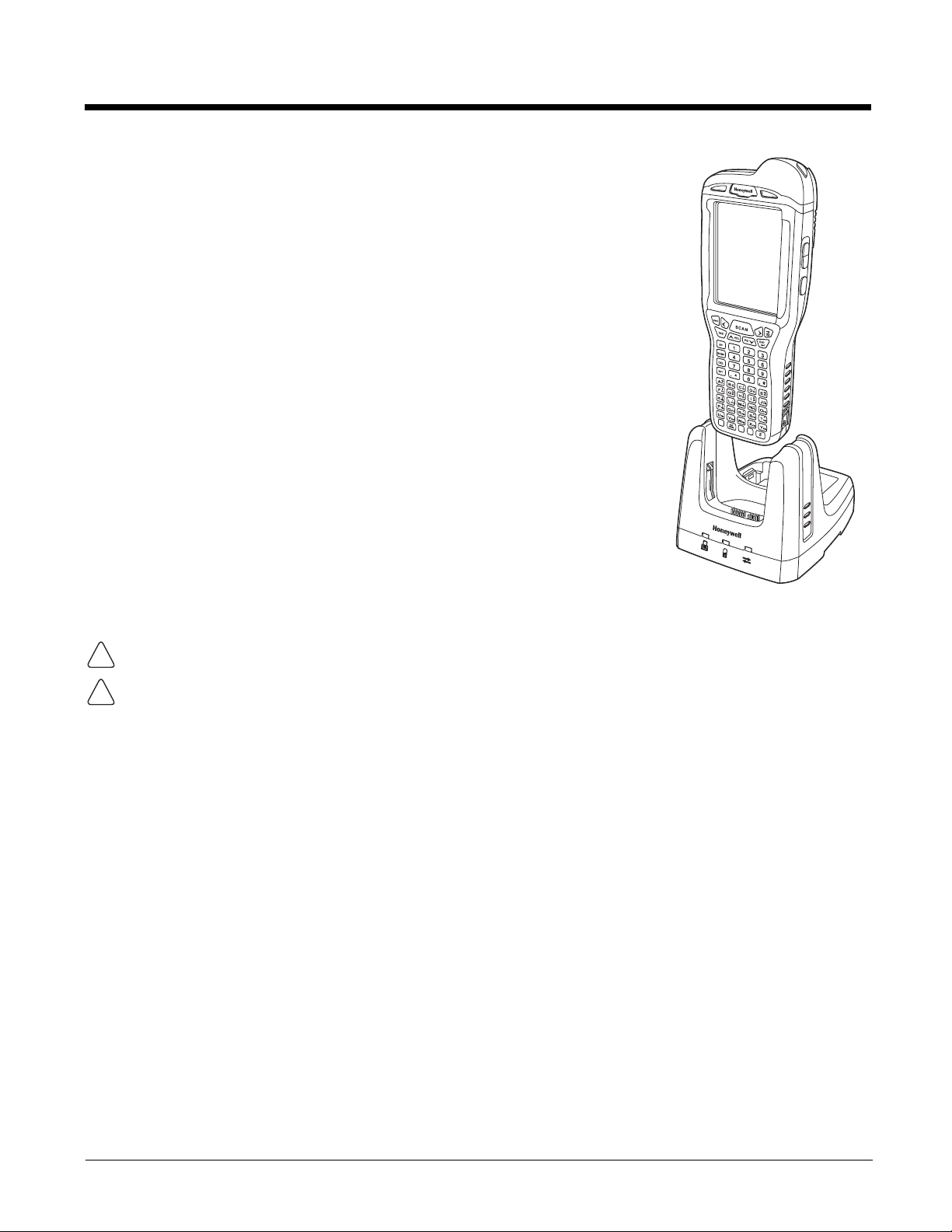
Dolphin 99EX HomeBase Device (Model 99EX-HB)
Overview
As the hub of your Dolphin system, the Dolphin 99EX HomeBase (99EX-HB) charging and communication cradle supports both RS232 and USB communications, which make it able to interface with the
majority of PC-based enterprise systems.
The 99EX-HB charger is designed for use with battery pack models 99EX-BTSC (standard Li-poly 3.7 V,
11.3 watt hour) and 99EX-BTEC (extended Li-ion 3.7 V, 18.5 watt hour) manufactured for Honeywell
International Inc. and with Dolphin 99EX and 99GX model terminals.
The HomeBase is not designed for use in hazardous locations.
We recommend use of Honeywell peripherals, power cables, and power adapters. Use of any non-Honeywell
peripherals, cables, or power adapters may cause damage not covered by the warranty.
Unpacking the HomeBase
Open the shipping box and inspect the package to see that the following standard items are included:
• One Dolphin HomeBase, model 99EX-HB
• One power supply (see Power on page 12-5)
• One power cord
These items are needed to operate the HomeBase. If any items are missing or anything appears to be
damaged, contact your Customer Account Representative. Keep the original packaging in case you
need to return the HomeBase for service or to store the HomeBase while not in use.
Optional Equipment
A standard RS232 or a standard USB cable is required when using the HomeBase for communication
between the terminal and a host device.
Charge Time
The base completes a full charge of the main battery pack installed in the terminal seated in the terminal
well in 4 hours for the standard battery or 6 hours for the extended battery. The base completes a full
charge of the battery pack in the Auxiliary Battery Well (see page 12-2) in 4 hours for the standard battery or 6 hours for the extended battery.
Charging Process
The base also provides power to the intelligent battery charging system in all Dolphin terminals that
senses when a full charge has been achieved and switches to a trickle charge to maintain the full
charge.
Communications
Reliable data communications at speeds of up to 115K baud can be transmitted by the base through the
RS232 serial port. Using the Hi-Speed USB port, the data transmission rate goes up to 480 Mbps.
These bases cannot be physically connected to each other - sometimes referred to as “daisy-chained”.
12 - 1

Convenient Storage
!
!
Power/Dock LED
Auxiliary Battery Well
AUX Battery LED
COMM LED
Terminal Well
The intelligent battery charging system makes this base a safe and convenient storage receptacle for
your Dolphin terminal.
Capacity
The base holds one terminal and features an auxiliary battery well behind the terminal well that can
charge a battery pack independently of the terminal well. This means that one base can charge two battery packs: the one installed in the terminal and a spare.
We recommend use of Honeywell Li-ion or Li-poly battery packs. Use of any non-Honeywell battery may result
in damage not covered by the warranty.
We recommend use of Honeywell peripherals, power cables, and power adapters. Use of any non-Honeywell
peripherals, cables, or power adapters may cause damage not covered by the warranty.
Parts and Functions
Front Panel
Terminal Well
Place the terminal in this well to communicate with a host device, power the terminal, and
charge the installed battery pack. The base completely charges the main battery in a Dolphin
terminal in 4 hours for the standard 3.7V battery or 6 hours for the extended 3.7V battery. If the
host device is a workstation that uses ActiveSync, synchronization begins immediately.
Auxiliary Battery Well
See Auxiliary Battery Well on page 12-4.
12 - 2

Power/Dock LED
Indicates if power is supplied to the HomeBase and if a terminal is docked properly in the base.
This color means…
Red The HomeBase has power but no terminal is docked.
Green The HomeBase has power and the terminal is properly seated in the base.
AUX Battery LED
Indicates status of the battery charging in the auxiliary battery well; see Back Panel on page
12-4.
This color means…
Orange The auxiliary battery is charging.
Green The auxiliary battery has completed charging and is ready for use.
Red, Flashing The internal temperature of the auxiliary battery is too hot or there is a battery error.
For information about charging a battery in the auxiliary battery well, see page 12-6.
COMM LED
Charge the auxiliary battery in a cooler environment or replace the battery with a
new Honeywell Li-ion or Li-poly battery.
This is the communication LED. It indicates the status of data transfer between the Dolphin
terminal and the host device. The color of this LED differs if the base is using the serial or USB
port connection.
If using the serial port
This color means…
Red Serial data is being sent from the host device to the base.
Green Serial data is being sent from the base to the host device.
Orange Serial data is being sent in both directions at the same time.
If using the USB port
This color means…
Green A USB Connection is established with the host workstation.
12 - 3

Back Panel
Auxiliary Battery Well
DC Power Jack
RS232 Port
USB Port
Auxiliary Battery Well
The base enables you to charge an additional battery pack independently of the terminal well
in 4 hours for the standard 3.7V battery or 6 hours for the extended 3.7V battery. This feature
ensures that you can always have a fully-charged battery for your terminal. See Charging a
Spare Battery in the Auxiliary Battery Well on page 12-6.
USB Port
This USB port is USB v2.0 Hi-Speed compliant. Using a USB cable, you can connect the base
to a host device, such as a workstation. USB communication occurs through Microsoft
ActiveSync (v4.5 or higher) or Microsoft Windows Mobile Device Center (WMDC) depending
on the host workstation’s operating system. When the terminal is seated in the terminal well, it
is connected to the host device via the base.
Note: ActiveSync on your Dolphin terminal works with Windows Mobile Device Center on host
RS232 Port
Use the 9-pin, RS232 cable from Honeywell to connect this port to a peripheral device for
RS232 data communication. For more information, see Serial Connector on page 12-9.
DC Power Jack
Use the power cable from Honeywell that comes with the base to supply power to this power
jack. For more information, see Power on page 12-5.
workstations running Windows Vista or Windows 7 and with ActiveSync on host workstations
running Windows XP. For detailed information on ActiveSync and WMDC visit Microsoft's
Windows Mobile Web site.
12 - 4

Bottom Panel
Compliance Label
Serial Number Label
!
Power Cable
A/C Power Cord
Power
Adapter
For details on how to mount the HomeBase, see Mounting the HomeBase on page 12-9.
Power
The base requires 12 Volts DC input for communications, battery charging, and power output to the terminal; the power adapter included with the base converts the voltage from the AC power source to
12 Volts DC. Use only UL listed power supply, which has been qualified by Honeywell, with output rated
at 12VDC and 3 amps with the device. The operating temperature range is -10° to 50°C (14° to 122°F).
Honeywell recommends that you leave the base connected to its power source at all times, so that it is
always ready to use .
We recommend use of Honeywell peripherals, power cables, and power adapters. Use of any non-Honeywell
peripherals, cables, or power adapters may cause damage not covered by the warranty.
Connecting Power to the HomeBase
1. Plug the A/C power cord into the power adapter.
2. Plug the power cable into the power connector on the back of the HomeBase.
3. Plug the A/C power cord into a grounded power source. The base is now powered. The Power/Dock
LED on the HomeBase illuminates solid red to indicate the HomeBase has power and no terminal is
docked.
12 - 5
Charging the Main Battery
!
!
The base powers the terminal and fully charges its main battery pack in
4 hours for the standard battery or 6 hours for the extended battery. The
terminal contains an intelligent battery charging system that protects the
battery from being damaged by overcharging. The unit senses when a
battery pack is fully charged and automatically switches to a trickle
charge that maintains the battery at full capacity. Therefore, terminals
may be stored in the base without damage to the terminals, battery
packs, or peripherals.
To check battery power, use the Power system setting; see Power on
page 7-16. For more information about Honeywell batteries, see
Batteries on page 3-13.
To Power a Terminal and Charge its Main Battery
1. Install the battery pack in the terminal; see Install the Main Battery
Pack on page 2-1.
2. Verify the base has power. If the Power/Dock LED is not
illuminated, see Connecting Power to the HomeBase on page 12-5.
3. Slide the terminal into the terminal well. The Power/Dock LED
changes to green. The charging begins immediately if required by
the Dolphin terminal.
Ensure all components are dry prior to mating terminals/batteries with peripheral devices. Mating wet
components may cause damage not covered by the warranty.
We recommend use of Honeywell Li-Ion or Li-poly battery packs. Use of any non-Honeywell battery may result
in damage not covered by the warranty.
Charging a Spare Battery in the Auxiliary Battery Well
The auxiliary battery well located on the back of the base charges a spare battery independently of the
terminal well. The Aux Battery LED on the front panel indicates the status of the battery in this well.
Charge time is 4 hours for the standard battery pack or 6 hours for the extended battery pack; see
Auxiliary Battery Well on page 12-4.
1. Insert the battery at an angle so the battery pack contacts and the auxiliary well contacts align.
2. Snap the battery into place with a hinging motion. The Aux Battery LED lights orange.
3. Use the AUX Battery LED to monitor the charging progress. The LED lights green when the auxiliary
battery has completed charging and is ready for use.
Note: If the AUX Battery LED flashes red, the internal temperature of the battery is too hot or there is a battery error.
Charge the auxiliary battery in a cooler environment or replace the battery with a new Honeywell Li-ion or Lipoly battery.
12 - 6
 Loading...