

Page 1
968XTP
Z
Y
X
(inward
swinging)
(outward
swinging)
Axis Minimum Make
/
Maximum Break
/
X
Y
Z
DOOR
Door
Frame
#6
3.5 mm( )
Screw
1/2”
(12.7 mm)
Open
#8
(4.1 mm)
Screw
#8
(4.1 mm)
Screw
DOOR
Align edges
Adjust height
with spacers
968XTP Maximum Security Switch - Installation Instructions
BALANCED MAGNETIC
HIGH SECURITY SWITCH
Approach Distance
inches / mm
0.17 / 4.3 0.42 / 10.6
0.53 / 13.5 0.72 / 18.2
0.23 / 5.7 0.54 / 13.7
Removal Distance
inches / mm
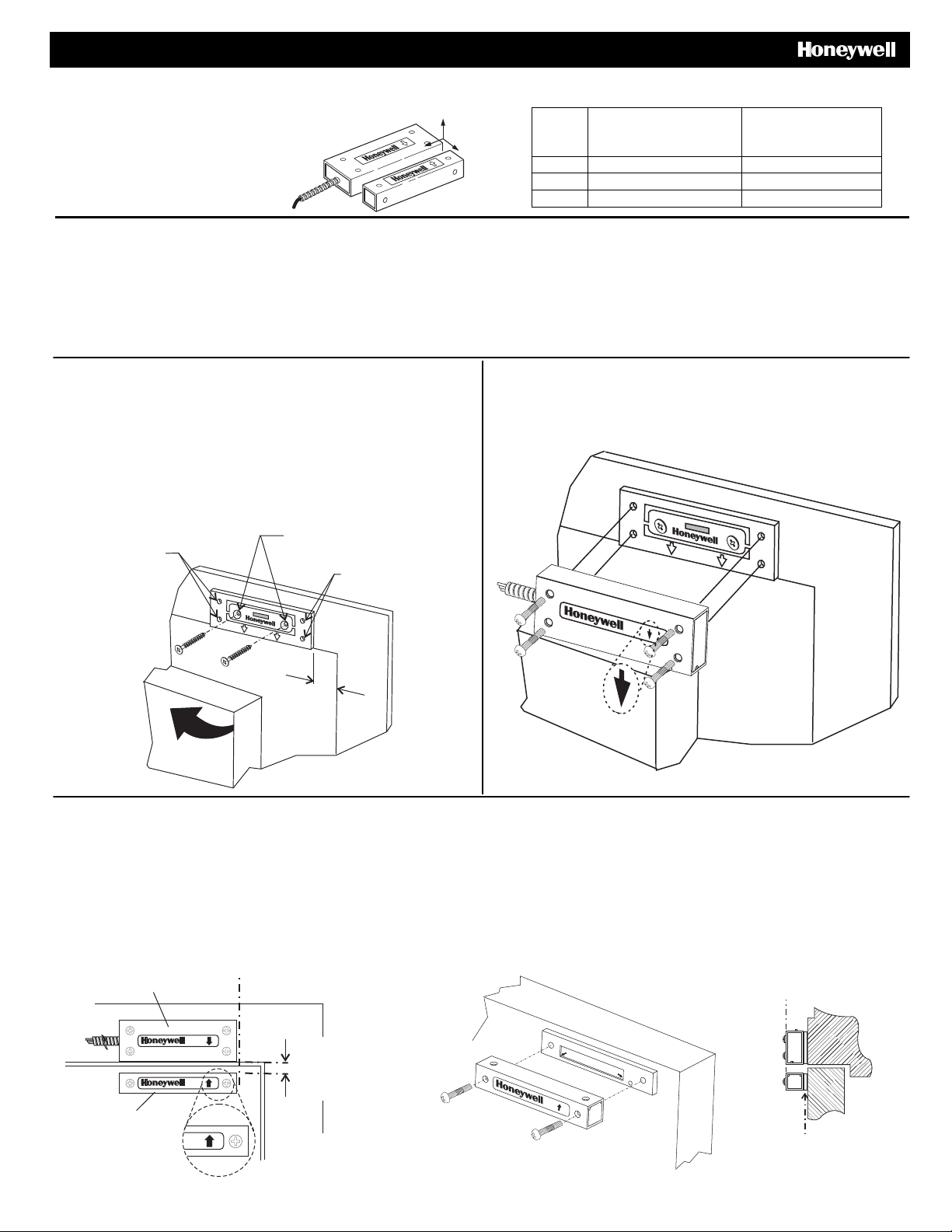
Inswinging Door Instructions
Honeywell’s 968XTP Maxiumum Security Magnetic Switch is intended to monitor the open or closed position of doors, windows, machinery
safety barriers or other movable assemblies in critical environments where an attempt to defeat the switch is a concern. The switch includes
numerous design features that make it highly defeat-resistant, reduce false alarms and provide for easy and accurate installation.
The performance of the 968XTP is unaffected by the type of surface on which it is mounted (steel or wood). The 968XTP features an
attack-resistant steel jacketed cable.
Step 1 - Install the Tamper Plate
• Line up the edge of the tamper plate with the edge of the door
frame, 1/2” (12.7 mm) [minimum] from the side edge. The
arrows on the tamper plate must be pointing toward the door.
• Mark the six hole centers for drilling pilot mounting holes.
• Drill two #6 (3.5 mm) pilot holes where shown.
• Drill four #8 (4.1 mm) pilot holes where shown.
• Mount the tamper plate in place using two #6 (3.5 mm) screws
[provided].
Step 2 - Install the Switch
• Install the switch assembly to the tamper plate with four
#8 (4.1 mm) screws [provided]. Make sure that the arrow is
pointing toward the door.
Step 3 - Install the Magnet
• Align the edges of the magnet assembly to the edges of the switch assembly.
• Position the magnet assembly so the arrow faces the arrow of the switch assembly.
• Important: Gap distance must be 7/16 ±1/16” (11.1 mm ±1.6 mm).
• Mark the mounting holes, drill pilot holes for #8 (4.1 mm) screws [provided].
• Use the magnet spacer plates to align the front surface of the magnet to match the front surface of the switch.
• Verify that the arrow on the magnet assembly is facing the arrow on the switch assembly.
• Install the necessary spacer plates and magnet assembly on the door with two #8 (4.1 mm) screws [provided].
• See Supplemental Information for wiring instructions.
Magnet Assembly
Switch Assembly
Align edges
7/16”
(11.1 mm)
Gap
SEPARATE FOR USE
WITH MAGNET ONLY
TAMPER
SCREW
- 1 -
PRELIMINARY DRAFT 11/4/09
Page 2
OPEN
Door
Frame
7/16”
11.1 mm
Align
Edges
Area to be
protected
3/16”
4.8 mm
Door
Frame
DOOR
Das
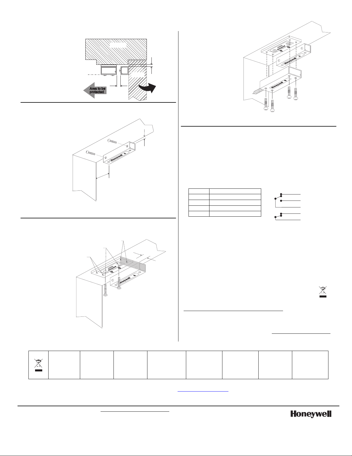
Outswinging Door Instructions
General Guidelines
• Mount the magnet
assembly to the
door, mount the
switch assembly to
the frame.
Step 1 - Install the Magnet
• Place the magnet
2” (51 mm)
[minimum] from
the side of the
door frame and
3/16” (4.8 mm)
from the top.
3/16”
(4.8 mm)
• Mark the two
mounting holes
and drill pilot holes
for #8
(4.1 mm) screws
[provided].
Frame
2” (51 mm)
Minimum
Door
• Mount the magnet
on the door using
two #8 (4.1 mm)
screws with the Honeywell label surface facing down and the arrow
pointing away from the door.
Step 2 - Install the Tamper Plate
• Line up the edge
of the tamper
plate to the edge
of the magnet.
Make sure the
arrows on the
tamper plate are
(4.1 mm)
Screw
#8
#6
(3.5 mm)
Screw
pointing toward
the door.
• Measure the gap
distance 7/16”
±1/16” (11.1 mm
±1.6 mm).
• Mark the
mounting holes
Frame
and drill pilot
holes for two #6
(3.5mm) and four
#8 (4.1 mm) screws [provided].
•
Mount the tamper plate in place using two #6 (3.5 mm) screws.
#8
(4.1 mm)
Screw
DOOR
7/16”
(11.1 mm)
Align edges
Door
Step 3 - Install the
Switch
• Verify that the arrow
on the switch
assembly is facing
the arrow on the
magnet assembly.
• Mount the switch
assembly to the
tamper plate using
four #8
(4.1 mm) screws
[provided].
• See Supplemental
Information for wiring instructions.
Supplemental Information
• The normal condition of the 968XTP is when it is reporting secure,
energized by the magnet.
• The two white tamper wires will be closed when the tamper switch
is in secure condition.
• The tamper contacts should be connected to a 24 hour circuit to
trigger an alarm any time the switch module is tampered with.
• Maximum contact ratings depend on the voltage put through the
switch. They are 250 mA at 12 V or less and 125 mA at 24 V. The
tamper circuit can handle a maximum of 1 Amp.
Black Common
Green Normally Closed (NC)
Red Normally Open (NO)
White Tamper NC
White Tamper NC
Notes
• To minimize tamper potential, the 968XTP should be installed inside the
perimeter being protected.
• The switch assembly / magnet combination is designed to have a
nominal gap of 0.45” (11.4 mm). The system will go into alarm
condition if the gap is approximately 0.63” (16.0 mm) and greater,
or approximately 0.27” (6.9 mm) or less. To account for system
tolerances, a 7/16” ±1/16” (11.1 mm ±1.6 mm) gap has been specified
in these instructions. The minimum make gap is 0.53” (13.5 mm).
Approvals/listings:
cULus listed
EN 50131-2-6:2008 Security Grade 3 Environmental Class II;
Certified by VdS.
Suitable for connection to an EN 60950 Class II
Limited Power Source in European Installations.
For any additional information, please refer to our Website,
www.honeywell.com/security/emea/hscdownload or contact:
Honeywell Security Group
Newhouse Industrial Estate
Motherwell
Lanarkshire ML1 5SB
United Kingdom
www.honeywell.com/security
Wiring
Green
NC
Red
NO
Black
COM
White
Tamper NC
White
Tamper NC
Tel: +44(0)1698 738200
Email: UK64Sales@Honeywell.com
For the latest U.S. warranty information, please go to: www.honeywell.com/security/hsc/resources/wa or
Please contact your local authorized Honeywell representative for product warranty information.
2006 Honeywell International Inc. Honeywell is a registered trademark of Honeywell International Inc.
All other trademarks are the properties of their respective owners. All rights reserved.
The WEE E symbol.
It indicates this
product is t o be
recycling an d not
been thrown away
in a dus tbin.
Le symbole DEEE. Il
indique que ce
produit doit être
recyclé et q u’il n e
doit pas être j eté à la
poubelle.
WEEESymbol. E s
bedeutet, dass
dieses Produkt
recyclebar ist und
nicht in den
Hausmüll gehört
Símbolo W EEE Indica
que este pr oducto es
para recicl ar y que no
se debe arrojar al cubo
de basura
Simbolo RAEE. Indica
che questo prodotto
deve essere riciclato e
non può essere gettato
nel secchio della
spazzatura
For patent information, see www.honeywell.com/patents
Symbol WEEE. To
označuje, že tento
výrobek má být
recyklován a ne být
vyhozen do popelnice.
WEEE sembolü. Bu
ürüne geri dönüşüm
yapılması gerektiğini
ve çöp kutusuna
atılmaması
gerektiğini belirtir.
Symbol WEEE.
Oznacza, że produkt
należy poddać
recyklingowi i nie
można wyrzucać go do
pojemników na śmieci.
Ê5-051-649-00HNŠ
P/N 5-051-649-00J 10/13 Rev A
 Loading...